VI. Filtration and Cooling Circuit
(continued)
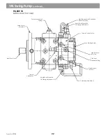
FIGURE 10
ENGINE COMPARTMENT LEFT SIDE
Reservoir Air Pressure
Regulator
Swing Suction
Filter & Gauge
Recirculation Return
Filter & Gauge
Pop Up Filter Indicator
Pilot Filter
Reservoir Air
Pressure Gauge
Air
Breather
Pilot Pump
Recirculation
Pump
Air Pressure
Drain
Thermal
Bypass Valve
Pressure
Reducing Valve
Pilot
Manifold
NOTE!
NOTE!
NOTE!
NOTE!
NOTE!
For location of the filters in the hydraulic system
See Figure 11.
13
XL 4100/XL 5100 HYDRAULIC SYTEM OPERATIONS MANUAL
Form No. 29703
Summary of Contents for XL4000
Page 2: ......
Page 73: ......
Page 76: ... 5MP ...
Page 145: ......
Page 146: ......
Page 160: ......
Page 161: ......
Page 162: ......
Page 175: ......
Page 176: ......
Page 177: ......
Page 178: ......
Page 192: ......
Page 193: ......
Page 194: ......
Page 207: ......
Page 208: ......
Page 210: ...500P ...
Page 229: ......
Page 230: ......
Page 245: ......
Page 246: ......
Page 247: ......
Page 248: ......
Page 265: ......
Page 266: ......
Page 267: ......
Page 268: ......
Page 280: ......
Page 281: ......
Page 282: ......
Page 297: ......
Page 298: ......
Page 299: ......
Page 300: ......
Page 301: ......
Page 302: ......
Page 303: ......
Page 304: ......


