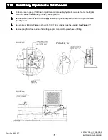
The Diverter Valve (8063-4028) is located in the front valve bank, next to the inlet section. The diverter valve is
connected to the rear valve bank inlet off the “B” port of the diverter valve.
The diverter valve performs a very important function in the hydraulic system by controlling the flow path of oil
from the two pump groups of the main pump. This valve allows excess oil in either valve bank to be made
available to the other valve bank. It also gives priority of oil to the front valve bank (boom hoist and tool) in
low flow, high pressure situations. The action of the diverter makes simultaneous function possible and prevents
any function from starving for oil in low flow, high pressure conditions.
The easiest test for diverter function is using the boom and tool circuits. As with all other hydraulic testing on
XL SERIES machines, the engine should be at full RPM and the oil warmed to at least 120°F. Place the boom level,
fully retracted and fully open with the tool against the stop. Let off both joysticks. Run the boom at full speed to
extend and move the tool joystick to stall the tool in the open position, then let off the tool. If the diverter is working
correctly, the boom will slow slightly, then speed up again when tool is let off. If the diverter is failed, when the tool
comes to high pressure the boom will stop or very nearly stop. Then when the high pressure (tool) is let off, after
1-2 seconds, the boom will start to extend again. If the problem is diverter sticking, this test may have to be
repeated several times to confirm it.
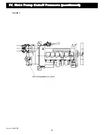
See Figure 11.
If gauges are being used during this test, you need a high pressure (10,000 psi) gauge on the inlet test port of
each valve bank. Note the pressure when the boom starts running and watch it as the tool is brought to high
pressure. The two gauges will rise, but will probably not be equal if the diverter is working correctly. If the diverter
is defective, the gauge on the front valve will be 2,000 - 2,050 psi (tool regulator setting may be lower on some
“special” machines). The gauge on the rear test port will drop to 500 - 800 psi and will not recover to the boom
running pressure of 1,000 - 1,300 psi until the boom starts to run again. When pressure is let off the tool, the
front gauge will also drop.
See Figure 11.
If a diverter fails, it should be replaced. Always make sure the valve section shims (8093-4324) are in place at the
tie bolt holes when replacing a section. Use the parts book for correct tie bolt torque and torque sequence.
IX.
IX.
IX.
IX.
IX. Di
Di
Di
Di
Divvvvver
er
er
er
erter
ter
ter
ter
ter V
V
V
V
Valv
alv
alv
alv
alve
e
e
e
e T
T
T
T
Testing
esting
esting
esting
esting
FIGURE 11
XL 5110 HYDRAULIC PRESSURE
SETTING MANUAL
(SUPPLEMENTAL PRESSURES)
Form No. 29626 2/97
11
Summary of Contents for XL4000
Page 2: ......
Page 73: ......
Page 76: ... 5MP ...
Page 145: ......
Page 146: ......
Page 160: ......
Page 161: ......
Page 162: ......
Page 175: ......
Page 176: ......
Page 177: ......
Page 178: ......
Page 192: ......
Page 193: ......
Page 194: ......
Page 207: ......
Page 208: ......
Page 210: ...500P ...
Page 229: ......
Page 230: ......
Page 245: ......
Page 246: ......
Page 247: ......
Page 248: ......
Page 265: ......
Page 266: ......
Page 267: ......
Page 268: ......
Page 280: ......
Page 281: ......
Page 282: ......
Page 297: ......
Page 298: ......
Page 299: ......
Page 300: ......
Page 301: ......
Page 302: ......
Page 303: ......
Page 304: ......


