XL 4100/5100 HYrDARAULIC SYSTEM OPERATIONS MANUAL
Form No. 29703
X11. Control Valves (continued)
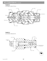
The diverter valve is a special valve assembly located in the front valve bank. The assembly consists of a dummy
spool, retainer plates (to prevent spool movement), a special compensator with integral shuttle assembly, a cap
on A port, reservoir plug for the A port option, and a dummy relief plug (GRADALL P/N 8093-4350) for the
B port option.
See Figure 55
The load sense system is not fitted to the diverter valve. As the pump generates
flow, the diverter valve reacts to flow and pressure requirements within the valve banks. The diverter valve
compensator pump cavity receives fluid from pump port A2 valve B port (connected to the rear valve bank)
and pump port A1.
The diverter valve circuit consists of the valve and a hose-to-pump inlet on the rear valve bank. In operation, the
special compensator spool reads fluid pressure from both pump sections. Excess fluid flow to the valve bank can
cause pump pressures to increase. According to fluid flow requirements in the valve bank, fluid causing such an
increase in pressure will be diverted to the other valve bank. This allows simultaneous function. Fluid flow within
this circuit can occur in any direction. Fluid from the rear valve bank can be sent to the front valve bank; fluid
from the front valve bank can be sent to the rear valve bank.
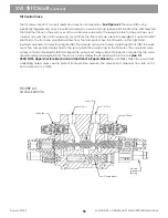
See Figure 56
In low pump flow conditions, the diverter valve gives priority for fluid from pump port A2 to be supplied to the
bucket or hoist circuits. If this priority exists, pump port A2 supplies fluid to the front valve bank while pump
port A1 supplies fluid to the rear valve bank. When low flow conditions end or demand for fluid from the
bucket or hoist valves ends, the diverter valve again allows fluid movement between valve banks.
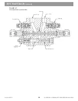
See Figure 57
The maximum flow rate in or out of the B port is equal to the pump section capacity (60 GPM). This maximum
flow rate will vary based on hydraulic system demand. No adjustments exist within the diverter valve.
XIII. Diverter Valve/Circuit
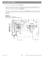
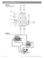
FIGURE 54
CONTROL VALVE - TORQUE VALVES (TYPICAL)
47
50 ft.-lb.
6 ft.-lb.
10 ft.-lb.
10 ft.-lb.
50 ft.-lb.
8 ft.-lb.
50 ft.-lb.
B Port
A Port
50 ft.-lb.
Summary of Contents for XL4000
Page 2: ......
Page 73: ......
Page 76: ... 5MP ...
Page 145: ......
Page 146: ......
Page 160: ......
Page 161: ......
Page 162: ......
Page 175: ......
Page 176: ......
Page 177: ......
Page 178: ......
Page 192: ......
Page 193: ......
Page 194: ......
Page 207: ......
Page 208: ......
Page 210: ...500P ...
Page 229: ......
Page 230: ......
Page 245: ......
Page 246: ......
Page 247: ......
Page 248: ......
Page 265: ......
Page 266: ......
Page 267: ......
Page 268: ......
Page 280: ......
Page 281: ......
Page 282: ......
Page 297: ......
Page 298: ......
Page 299: ......
Page 300: ......
Page 301: ......
Page 302: ......
Page 303: ......
Page 304: ......

