109
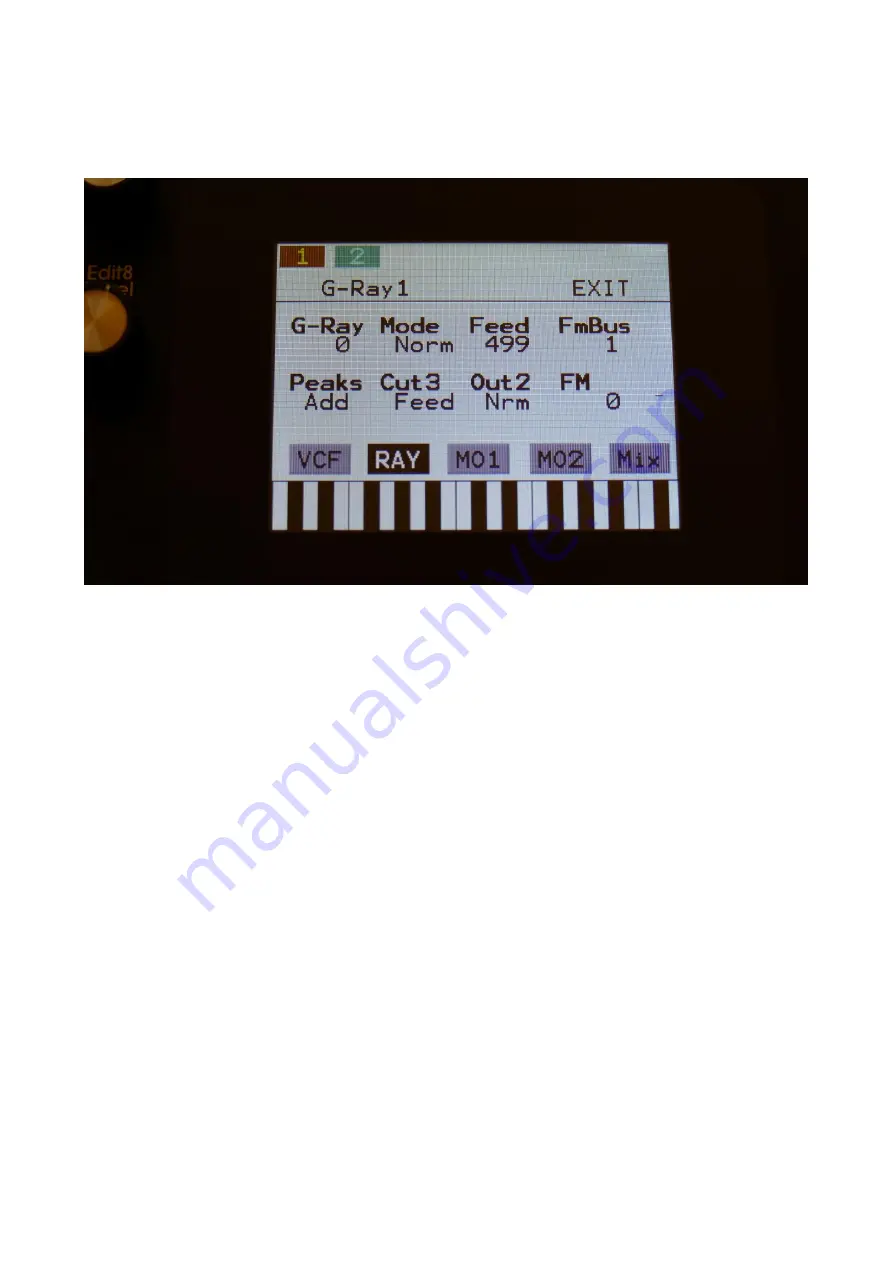
Analog Filterboards G-Ray page
Touch the RAY touch button, to enter this page.
The VU-meter at the right of the screen, shows the filter output activity.
G-Ray:
Adjusts the amount of g-RAY intermodulation. 0: no g-RAY, 3: max g-RAY. Range: 0 to 3.
Mode:
G-Ray mode.
-Norm:
Normal 1:1 feedback.
-Neg:
1:1 feedback with the signal inverted (a 180 degree phase shift)
-Ultr:
Boosted feedback.
-Uneg:
Boosted feedback with the signal inverted (a 180 degree phase shift)
Feed:
0 to 511. G-Ray feedback level.
FmBus:
1 to 8. The audio bus, that will apply the audio signal for FM.
Peaks:
Selects how the Peaks parameter should interact with the Cutoff frequency parameter:
-Add:
The value of the Peaks parameter is added to the Cutoff value.
-Sub:
The value of the Peaks parameter is subbed from the Cutoff value.
-Alig:
The value of the Peaks parameter are alligned around the Cutoff value.
-Sepa:
The value of the Peaks parameter are a totally separate value, and are not affected by the
Cutoff value.
Summary of Contents for Little deFormer 3
Page 1: ...1 Gotharman s Little deFormer 3 Granular Workstation User Manual V10 26 ...
Page 8: ...8 I hope that you will deform some great tracks ...
Page 18: ...18 ...
Page 19: ...19 Turn it on Push the I on the power switch Your LD3 should now turn on ...
Page 39: ...39 Exit Exits from any page ...
Page 41: ...41 ...
Page 50: ...50 Accessing The Synth Part Pages From the Preset Song Select screen Touch the EDIT field ...
Page 125: ...125 3xBPF Mix between LPF BPF HPF and 3x BPF ...
Page 205: ...205 Fade When this parameter is turned up each grain will fade in and out to minimize clicks ...
Page 224: ...224 Entering the Sequencer From the Preset Select Screen touch the EDIT field ...
Page 225: ...225 Touch SEQ on the navigation bar in the top of the screen ...
Page 255: ...255 On this page touch TRIG ...
Page 259: ...259 You should now enter this page Touch the REC touch button ...
Page 263: ...263 You should now have entered this page Touch NOTE TRACK 1 16 to enter the note track page ...
Page 265: ...265 Touch MAIN ...
Page 287: ...287 More preset parameters Setup From the Preset Select page touch the Edit field ...
Page 288: ...288 On the navigation bar at the top of the screen touch MOR ...
Page 305: ...305 Parameter snap mode will now be turned on To turn it off touch it again ...
Page 320: ...320 On the navigation bar at the top of the screen touch MOR ...
Page 345: ...345 When you are finished recording your sample touch the STOP button ...
Page 358: ...358 LD3 will now show When it has found some chop points it will return to the Chop page ...
Page 360: ...360 Touch the sample slot 1 name to open the sample select page ...
Page 361: ...361 Select the sampling touch OK and touch the OSC touchbutton ...
Page 365: ...365 To delete the sample touch Yes If you regret touch No to return to the Sample Edit page ...
Page 400: ...400 11 Touch the UPD button ...
Page 403: ...403 Programming processor counter in the bottom counts up ...
Page 418: ...418 Remove the 4 screws in the corners of the left end panel using the Phillips screwdriver ...
Page 419: ...419 Take the left end panel a bit out ...
Page 421: ...421 Take the right end panel a bit out ...
Page 422: ...422 Remove the plastic frame from the left end panel ...
Page 428: ...428 The screw and the washers that is holding the filterboard in place ...
Page 436: ...436 Remove the 4 screws in the corners of the left end panel using the Phillips screwdriver ...
Page 437: ...437 Take the left end panel a bit out ...
Page 439: ...439 Take the right end panel a bit out ...
Page 440: ...440 Remove the plastic frame from the left end panel ...
Page 443: ...443 Flip LD3 around so that the front panel is facing downwards ...
Page 446: ...446 Near the connector to the knob board are the third connector needed for the analog board ...
Page 447: ...447 The analog board itself ...
Page 448: ...448 When turned upside down the 3 connectors that needs to connect to the LD3 mainboard shows ...
Page 451: ...451 Check an extra time that the connectors fits THIS IS VERY IMPORTANT ...
Page 452: ...452 It should now look like this ...
Page 454: ...454 Tighten the screw using the Allen screwdriver ...
Page 455: ...455 Locate the cable on the left end panel that is connected to audio in out 3 4 ...
Page 456: ...456 Connect this to the angled connector on the analog board as shown on the picture ...
Page 459: ...459 Turn LD3 over so the front panel is facing upwards again ...
Page 461: ...461 Written by Flemming Christensen Gotharman 2019 ...


