


GKP-2302 User Manual
198
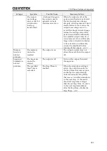
Category
Symptom
Possible Cause
Necessary Actions
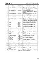
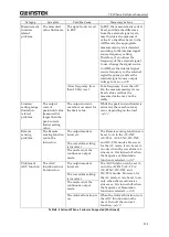
Output-related
problem
The measured
voltage is
different from
the setting
value.
Unnecessary
items are set (for
example, the AC
voltage setting
remains for the
DC output).
Check for the setting again. In the ADD
mode, check on the external input
signal and gain setting as well.
The limiter is
activated (the
limiter icon is
displayed).
For a load with lower impedance, the
limiter is activated to make the output
lower than the setting value. Check on
the limiter setting.
The waveform is
set to CLP
(clipped sine
wave) and the
Type is set to
Clip (specified
clip ratio mode).
In the specified clip ratio mode, the
output voltage setting means a value
for the waveform before being clipped.
To set a value for the clipped
waveform, set the Type to the specified
crest factor mode (Type: CF).
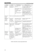
An error
message is
displayed.
The protection
function was
activated due to
overload.
Connect a load within the maximum
output range or decrease the output
voltage setting.
Excessive signal
level of the
signal generator.
When the signal source is EXT or ADD,
lower the level of the connected signal
generator or decrease the external input
gain.
The ambient
temperature is
high.
Decrease the ambient temperature
when using the product. The maximum
current may decrease over 40 °C.
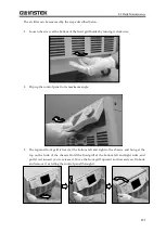
Air filters are
clogged.
Clean the air filters by referring to
8.2 .
Around the
front panel air
inlet or rear
panel air outlet,
there is
something
blocking the air
flow.
Install the product so as to satisfy the
installation conditions described in
Measurement
function-related
problem
The measured
voltage or
current is not
displayed
correctly.
The display
selection is not
right.
Select RMS for AC. Otherwise, the
correct value is not displayed.
The measured
value is
displayed as
"----".
It is out of the
synchronization
frequency
measurement
display range.
Set the synchronization signal source
frequency to a value within the
synchronization frequency
measurement display range.
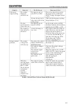
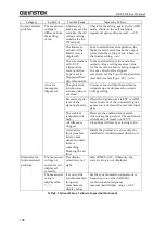
Table 8-3 Actions When a Failure is Suspected (Continued)
Summary of Contents for GKP-2302
Page 15: ...1 1 OUTLINE 1 1 Overview 2 1 2 Features 2...
Page 28: ...GKP 2302 User Manual 14 Nothing is connected to the output terminal...
Page 60: ......
Page 186: ......
Page 187: ...173 5 DESCRIPTION OF SCREEN AND MENU 5 1 Screen Configuration 174 5 2 Menu Composition 177...
Page 195: ...181 6 REMOTE CONTROL 6 1 Communication Interface 182 6 2 Remote Local State Switching 188...
Page 216: ......
Page 222: ......


