


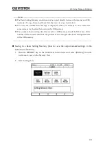

4.6 Using Clipped Sine Wave
111
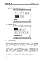
もとの正弦波
クリップ
正弦波
Original sine
wave
Clipped
sine wave
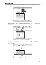
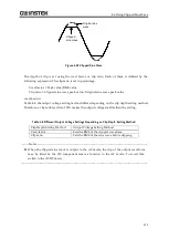
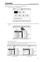
Figure 4-22 Clipped Sine Wave
The depth of clip is set using the crest factor or clip ratio. Each of them is defined by the
following expression. The clip ratio is set in percentage.
Crest factor = Peak value/RMS value
Clip ratio = Clipped sine wave peak value/Original sine wave peak value
As shown in
Table 4-8, the output voltage setting method differs depending on the clip depth setting method.
Therefore, a clip ratio less than 100% makes the output voltage smaller than the setting.
Table 4-8 Different Output Voltage Settings Depending on Clip Depth Setting Method
Clip Depth Setting Method
Output Voltage Setting Method
Crest factor
Sets the RMS of the clipped waveform
Clip ratio
Sets the RMS of the sine wave before clipping
--------
Notes
----------------------------------------------------------------------------------------------------------------
When the clipped sine wave is output in the AC mode, the clip of the output waveform
may be tilted by the DC component remove function in the AC mode. To avoid this,
switch to the ACDC mode.
---------------------------------------------------------------------------------------------------------------------------------
Summary of Contents for GKP-2302
Page 15: ...1 1 OUTLINE 1 1 Overview 2 1 2 Features 2...
Page 28: ...GKP 2302 User Manual 14 Nothing is connected to the output terminal...
Page 60: ......
Page 186: ......
Page 187: ...173 5 DESCRIPTION OF SCREEN AND MENU 5 1 Screen Configuration 174 5 2 Menu Composition 177...
Page 195: ...181 6 REMOTE CONTROL 6 1 Communication Interface 182 6 2 Remote Local State Switching 188...
Page 216: ......
Page 222: ......


