


GKP-2302 User Manual
174
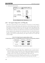
5.1
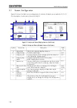
Screen Configuration
Figure 5-1 shows the basic screen configuration. It consists of display areas marked as "a" to "h".
The description of each area is shown in Table 5-1.
a
b
c
d
e
f
g
h
i
Figure 5-1 Component Name (Display Areas on the Screen)
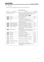
Table 5-1 Component Name (Display Areas on the Screen)
Symbol
Area name
Description
Refer
to
a
Screen title
Title of the currently displayed screen.
—
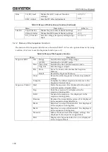
b
Output range
Current output range.
c
Output mode
Current output mode. It is displayed in the format of
"AC/DC mode - Signal source."
d
Output phase
mode
Current output phase mode in the system.
1P2W: Single-phase two-wire
—
e
Status icon
The area where an icon is displayed when the product
enters the specific state, for example, when the limiter
is activated.
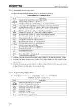
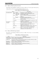
f
Measured value
area
The measured values are displayed. In the Simple
View, three items are enlarged.
g
Output display
area
The output setting is displayed. Make the output
settings in this area.
h
Soft-key
function
Shows the functions assigned to the soft-keys below.
i
Window
The window where the confirmation message is
displayed or you change the settings. It is displayed as
needed.
Summary of Contents for GKP-2302
Page 15: ...1 1 OUTLINE 1 1 Overview 2 1 2 Features 2...
Page 28: ...GKP 2302 User Manual 14 Nothing is connected to the output terminal...
Page 60: ......
Page 186: ......
Page 187: ...173 5 DESCRIPTION OF SCREEN AND MENU 5 1 Screen Configuration 174 5 2 Menu Composition 177...
Page 195: ...181 6 REMOTE CONTROL 6 1 Communication Interface 182 6 2 Remote Local State Switching 188...
Page 216: ......
Page 222: ......


