•Page
globalcontract.com
15
• Summer 2017
GLOBAL
Contract
INSTALLATION GUIDELINES
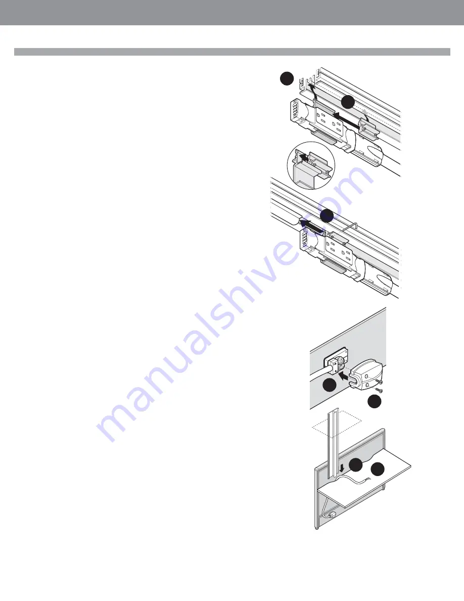
Electrical Feed Blocks and Duplex Receptacle Blocks share the same, extruded Mount-
ing Bracket and Mounting Bracket Retainer.
While the following illustrations depict installation of the Duplex Receptacle Block, the
same procedure is used to secure Electrical Feed Block.
STEP 5: Insert the Duplex Receptacle Block mounting bracket into the bottom groove
of the Diet panel frame as illustrated.
STEP 6: Insert the Duplex Receptacle Block retainer into the bottom groove of the Diet
panel frame. Align it with the Mounting Bracket.
STEP 7: Slide the Bracket / Retainer assembly snugly against the Duplex Receptacle
Block Spacer and use an allen key to spread the Bracket and the Retainer in the bot-
tom horizontal frame member.
STEP 8: Repeat the procedure on the opposite end of the panel. Ensure that the
Duplex Receptacle Blocks installed facing the same or opposite side of the panels are
in accordance with your fl oor plan specifi cations.
STEP 9: Power can be installed exiting the raceway cover in the left or right direction.
Base Feed:
Choose the direction corresponding with the location of the nearest fl oor monument.
Ceiling Feed:
Because the Ceiling Feed conduit (within the Power Pole) always rises through a
worksurface “scoop” above the Ceiling Feed panel entry, install the Ceiling Feed
conduit so it always points to the closest edge of a panel.
Close the Raceway Cover.
STEP 10: Hold the Ceiling Feed conduit in the desired direction against the closed
Raceway Cover and place the injection molded Power Cover over the protruding
Electrical Feed Block as illustrated.
STEP 11: Secure the cover with supplied screws.
STEP 12: Thread the Ceiling Feed conduit up, through the worksurface “scoop”.
STEP 13: Remove ceiling tile and slide aluminum Power Pole extrusion down,
through the worksurface “scoop”.
Note: If ceiling mounted objects prevent you from sliding the Power Pole down,
remove worksurface temporarily, but secure the worksurface back to the panels
because it is the scoop cut out in the worksurface that determines accurate location of
the Ceiling Power Pole.
There are two pairs of mounting keyholes punched in the aluminum Diet Power Pole.
One pair is at the base and another pair is just below desk height.
Diet Electrical installation
6
7
5
10
11
13
12


