background image

Glentek Inc.  208 Standard Street, El Segundo, California 90245, U.S.A.  (310) 322-3026 

42 

Omega Series Digital PWM Amplifier Manual 

Sample DBN operating sequence


1)    Write DBN Setup Data (Pulse Width, Interval, Config) to the drive processor. Set 

Interpolator/DBN_Mode

 to 

Setup/Cal

 to transfer the setup data to the DBN processor. 

2)       Write 

Num_DBN_Frames

, n, to drive processor. 

3)       Set 

Frame_Data_Index

 to 0. 

4)    Write frame Data beginning with frame[0].start, frame[0].stop…frame[n-1].start, frame[n-1].stop. The 

frame_data_index

 will auto-increment after each write so it is not necessary to update the index unless non-

sequential access is desired. 

5)       Set 

Interpolator/DBN_Mode

 to 

DBN_Load_Frames. 

The frames will be downloaded at 1 frame/PWM_Cycle 

(24kHz). 

6)    Monitor the 

DBN_Download_In_Progress

 bit if the 

Interp/DBN_Status

 register to determine if the download 

is complete. 

7)    When ready to begin the DBN sequence, change 

Interpolator/DBN_Mode

 to 

DBN_Enable

8)   Repeat steps 2-4 to download the next sequence of frames to the drive processor. 

9)    Wait for the executing sequence to complete by monitoring the 

DBN_Done

 bit of the 

Interp/DBN_Status

 reg-

ister. 

10)  Repeat steps 5-9 as desired. Changing the mode to 

DBN_Load_Frames

 will clear the 

DBN_Done

 bit and al-

low the next sequence to execute once the mode is changed back to 

DBN_Enable

11) If 

DBN_Enable

 mode is exited before the sequence has completed, the frames must be re-loaded to reset the 

sequence to frame 0. If the frames are not reloaded, the sequence will begin with the frame that was execut-
ing when the DBN was disabled. 

DBN Arming

Start position < Stop position (Direction positive) 

The trigger position is set to the start position. 

The DBN will arm once the absolute position is < the start position. 

The first DBN pulse will occur when armed and the absolute position >= start position. 

Once a trigger occurs the trigger position is updated to last_trigger_pDBN_Interval. 

If the motion is reversed before the stop position is reached and the absolute position becomes < the start posi-
tion, the trigger position is reloaded with the start position. 

Once the stop position has been exceeded, the next frame start position is loaded. 

Start position >  Stop position (Direction negative) 

The trigger position is set to the start position. 

The DBN will arm once the absolute position is > the start position. 

The first DBN pulse will occur when armed and absolute position <= start position. 

Once a trigger occurs the trigger position is updated to last_trigger_position-DBN_Interval. 

If the motion is reversed before the stop position is reached and the absolute becomes > the start position, the 
trigger position is reloaded with the start position. 

Once the stop position has been exceeded, the next frame start position is loaded. 


Summary of Contents for Omega SMC9930

Page 1: ...Preliminary INSTALLATION OPERATION MANUAL Omega Series Model SMC9930 Model SMC9975 with Interface Digital PWM Brush Brushless Servo Amplifiers...

Page 2: ...dates The network is electrically isolated for noise immu nity and includes data path redundancy for fault tolerant operation SynqNet eliminates the traditional noise prone 10V analog signal and reloc...

Page 3: ...puts A B and index channels passed to the controller Status indicator 7 segment display indicates amplifier status and fault codes Sine encoder interpolation Accepts 1Vpp sine cosine feedback and inte...

Page 4: ...Glentek Inc 208 Standard Street El Segundo California 90245 U S A 310 322 3026 4 Omega Series Digital PWM Amplifier Manual Amplifier Setup Software Motion Maestro...

Page 5: ...install disk is setup to utilize Install Shield to simplify installation There are only a few setup options offered In general you can press NEXT or YES until installation is complete When installati...

Page 6: ...arameters Opening of Communications Before MotionMaestro can be used communications must be established between the amplifier and the PC that MotionMaestro is running on Before opening communications...

Page 7: ...To view this dialog you must select the Tools option on MotionMaestro s main menu tool bar then select Model Info Here you will be able to view your firmware version and date amp model number power bo...

Page 8: ...there are two sets of check boxes for each signal Wkg and Amp Amp displays the current amp setting while Wkg dis plays the users choice The amp is automati cally updated as the Wkg box changes If Wkg...

Page 9: ...eters in the amplifier the amp must be disabled You can do this by clicking on the Disable Enable Amp button first then the Send Values To Amp button Pressing F1 displays the dialogs help text After t...

Page 10: ...red Rotary Selecting lin ear instead of rotary will display parameters that are specific to a linear motor Edit boxes that are not available are values that are calculated based on other parameters en...

Page 11: ...nd turns on off different traces You can monitor up to three traces at one time All traces are color coded on the Oscilloscope Display screen The Recording Data section is useful for recording test da...

Page 12: ...as been designed so that only those applicable to the situation at hand can be displayed These dialogs continuously send queries to the amplifier to determine the amplifiers current status The size an...

Page 13: ...rrants attention Current fold back is such a condition Display this dialog by selecting Status Warnings or via a button on MotionMaestro s toolbar Status All other amplifier conditions that are not a...

Page 14: ...he right Creating a Back Up Copy of Amplifier Parameters on Disk An amplifier s current parameter settings can be saved to a disk file that can later be used to configure another amplifier or to resto...

Page 15: ...gineer can determine the amplifier s true response to commanded signals The analog output is for reference use only It is not intended for control purposes At power on its value is undetermined until...

Page 16: ...Glentek Inc 208 Standard Street El Segundo California 90245 U S A 310 322 3026 16 Omega Series Digital PWM Amplifier Manual SynqNet Setup Guide...

Page 17: ...does not change to NO use MotionMaestro to determine the cause of the fault clear the cause and click the Clear Fault button again To zero the Actual Position click the Zero Position button on the Act...

Page 18: ...plifier by checking the Enabled Check box on the MoCon Motor Summary window Carefully rotate the motor shaft by hand and verity the motor rotates smoothly without any cogging torque or torque bias Com...

Page 19: ...Actual Position decreases Zero the DAC Offset Disable the Amp Set the Algorithm on the Config Tab of the Filter Summary Window back to PID Set the Error Limit Action on the Events Tab of the MoCon Mot...

Page 20: ...U16 162 Pre Amp Tab U16 163 Continuous Current Rating U15 See Parameter 166 for engineering conversion 164 Peak Current Rating U15 See Parameter 166 for engineering conversion 165 Bus Over Voltage Th...

Page 21: ...parameter 169 for engineering conversion 176 S V Phase ADC Offset I16 See parameter 169 for engineering conversion 177 T W Phase ADC Offset I16 See parameter 169 for engineering conversion 178 189 Spa...

Page 22: ...locity 0 Do not negate 4 Encoder Reverse 1 Negate Encoder 0 Do not negate 5 Hall Type 1 Special Halls e g reduced wire encoders 0 Standard Halls 6 7 Reserved 8 Interpolator En coder Fault Disable Inte...

Page 23: ...to 180 degrees 45 Commutation Lead Gain I16 Proportional to degrees RPM conversion TBD 46 Commutation Angle I16 Normalized to 180 to 180 degrees 47 49 Spare Commutation Initialisation Options 50 Init...

Page 24: ...curacy This limit is bypassed for the first eight edge corrections following a commutation reset power on reset or fault reset 68 69 Spare Current Loop Tuning 70 Loop Gain U15 0 to 32767 0 to 1 0 71 P...

Page 25: ...2768 to 32767 1 0 to 1 0 114 B1 I16 32768 to 32767 1 0 to 1 0 115 B0 I16 32768 to 32767 1 0 to 1 0 116 Scale I16 Bit shift used to scale coefficients to within 1 0 range Coefficients should be scaled...

Page 26: ...t 9 Phase R Measured Current 10 Phase S Measured Current 11 Phase T Measured Current 12 Phase R Commanded Voltage 13 Phase S Commanded Voltage 14 Phase T Commanded Voltage 15 Aux Command sum of all so...

Page 27: ...e This example demonstrates how to read existing encoder resolution and write a new encoder resolution 1 read 4 retrieve encoder resolution setting refer to page 27 2 0x200 hex decimal number for 512...

Page 28: ...r_C_Table R W N Using the data passed Pointer_C is set to one of the tabulated values in Error Reference source not found 0x14 Get_Monitor_C_Memory Set_Monitor_C_Memory R W N Using the data passed Poi...

Page 29: ...tion application programming interface MPI Direct commands Monitor_X_Table 0x0F 0x011 0x013 per page 34 Notes Interpolator option Only Interpolator mode must be setup cal to monitor these channels Sin...

Page 30: ...er page 34 Will clear all but NVRAM and CPLD faults which require a Hardware reset i e a power cycle Bus Under Volt age is now a warning Fault Count Direct command 0x09 per page 34 Always reads as 1 a...

Page 31: ...ct Command Note This example demonstrates how to read amp faults 1 0x08 Fault Read per page 34 2 0x00000860 hex decimal number for 100001100000 bin 3 Bit 5 100001100000 Invalid Hall State per page 36...

Page 32: ...Glentek Inc 208 Standard Street El Segundo California 90245 U S A 310 322 3026 32 Omega Series Digital PWM Amplifier Manual Reading Amp Fault Data by Using sqDriveMsg Command...

Page 33: ...bit warning word Warning Clear Direct Command 0x0B per page 34 Warnings and the warning flag are latching the warning code is held in a register until cleared Warning Count Direct Command 0x0B per pag...

Page 34: ...l Firmware Flash Download with Using Motion Console MoCon 1 Select Binary Download in SyqNode Summary window 2 Select Drive Processor 0 Firmware 3 Locate firmware file using Browse button 4 Highlight...

Page 35: ...Glentek Inc 208 Standard Street El Segundo California 90245 U S A 310 322 3026 35 SynqNet with Sine Interpolator and DBN SMC99XX 10X 001 000 See page 79 for model numbering SynqNet Setup...

Page 36: ...put a nd must be configured as an input in the Node logic to prevent driver contention 2 Set Encoder Type to Drive to read the interpolated date from the drive 3 Set Position1 Position2 Velocity Accel...

Page 37: ...and Cosine signals This swap may cause a step change in the interpolated position data and should only be performed when the drive is disabled The second switch is the drive processor s local encoder...

Page 38: ...Sine input to calibrate signal inaccuracies for improved interpolator accu racy This parameter should be set after selecting the encoder direction since changing the encoder direc tion swaps the sine...

Page 39: ...and Cosine input channels to reverse the encoder count direction 0 Do not swap Sine and Cosine input channels Bits 12 15 Interpolator Factor n 0 to 14 Setup Cal Interpolation factor 2 n 2 n interpolat...

Page 40: ...the drive processor to the Inter polator DBN processor and the calibrated sine cosine signals are continuously uploaded from the Interpo lator DBN processor to the drive processor and can be monitored...

Page 41: ...Sequence Completed must exit DBN_Enable Mode to clear 0 Sequence not completed Bit 12 DBN_Auto_Reenable 1 DBN auto re enable bit is set in Interpolator DBN_Config register 0 DBN auto re enable bit is...

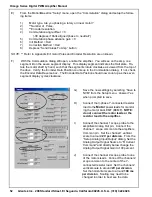
Page 42: ...mode is changed back to DBN_Enable 11 If DBN_Enable mode is exited before the sequence has completed the frames must be re loaded to reset the sequence to frame 0 If the frames are not reloaded the s...

Page 43: ...V differential max I 6 Encoder A Sine 7 Encoder B Cosine 8 Encoder B Cosine 9 Encoder Z Index 10 Encoder Z Index 11 Hall U 26LV32 or equivalent RS422 line receiver inputs Compatible with differential...

Page 44: ...inals of each optical output are available at the I O connector al lowing the ability to configure each output as sourc ing or sinking All outputs are controlled by the SynNet controller VCE max 35V I...

Page 45: ...standard 26LV31 or equivalent RS422 line drivers All outputs are controlled by SynqNet Controller Iout max 20mA O 34 TX_0 35 TX_1 36 TX_1 5VDC out Short circuit protected Pin Number Desctiption I O 3...

Page 46: ...I 6 Receive I 4 5 7 8 Earth ground Pin Number Description I O 1 Receive I 2 Receive I 3 Transmit O 6 Transmit O 4 5 7 8 Earth ground Connector Description Type 8 Pin Male Mating Connector RJ 45 Molex...

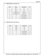
Page 47: ...Power I O Connector Pin Name Description I O 1 AC 1 AC I 2 AC 2 AC I 3 AC 3 AC I 4 Ext Regen Out Reserved O 5 Ext Regen Out Reserved O 6 R Motor Phase R O 7 S Motor Phase S O 8 T Motor Phase T O Appen...

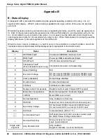
Page 48: ...ault or state Display Name Description 1 EEPROM Fault Parameter EEPROM checksum fault 2 RAM Fault Power up RAM read write test failed 3 CPLD Fault CPLD communication timeout 4 Interpolator Fault Sine...

Page 49: ...r Output Power Rated Peak SMC9930 100 135 260VAC 30 60 SMC9930 103 135 260VAC 30 60 SMC9975 100 50 135VAC 75 150 SMC9975 103 75 150 50 135VAC Appendix C Sine Encoder Interpolation Sine Cosine Input Ma...

Page 50: ...standard 26LV31 or equivalent RS422 line driver Iout max 20mA TX0 is controlled by the interpolator and should be configured as an input on the controller Divide by N function TX1 is controlled by the...

Page 51: ...ter with MotionMaestro installed B With the power off connect the motor encoder outputs and the Hall sensor outputs to the amplifier Leave the motor power leads disconnected Connect the RS232 serial c...

Page 52: ...ation dialog If not check the Encoder Data Reverse box The Encoder Data Position should now count up as the seven segment display cycles clockwise G Save the new settings by selecting Save to NVM from...

Page 53: ...ermine which BEMF waveform is in phase or 180 out of phase with the phase R command Label this lead Phase R NOTE For each phase R S and T one direc tion of rotation should cause the back EMF BEMF to b...

Page 54: ...set any current limits foldback thresholds to the desired operational settings Reset the Control Panel options to appropriately safe values Set the Analog Input Signal Gain back to the de sired operat...

Page 55: ...that you will enter in your Commutation dia log Note For better accuracy you may rotate by 10 turns and divide by 40 instead of 4 Common encoder line counts include but are not limited to 250 256 500...

Page 56: ...entek motor that is correctly com mutated where the encoder is not reversed FER 0 and the tachometer feedback is reversed TR 1 Commutation track signals and phase to phase BEMF 180 to 180 degrees As m...

Page 57: ...MI is called the device s Electromagnetic Compatibility EMC Equipment which is to be brought into the European Union legally requires a specific level of EMC Since this applies when the equipment is b...

Page 58: ...and provides electrical iso lation In addition it provides common mode filtering although the effect is limited in frequency by the interwinding capacitance Use of a Faraday shield between the winding...

Page 59: ...situation is similar to a leaky boat All the holes must be plugged to prevent sinking If the filter is mounted excessively far from the drive it may be necessary to mount it to a grounded conductive...

Page 60: ...should be used as the single point where circuits are grounded This will minimize common ground impedance noise coupling The ground bus bar GBB should be con nected to the AC ground and if necessary t...

Page 61: ...ial to meet European EMC requirements The following suggestions are recommended for all installations 1 Motor cables must have a continuous shield and be terminated at both ends The shield must connec...

Page 62: ...chine builder to ensure that the machine meets the appropriate requirements as installed RECOMMENDATIONS FOR GLENTEK AMPLIFIERS All amplifiers installed in a NEMA 12 enclosures or equivalent with wiri...

Page 63: ...locity or po sition There are many forms and methods by which commands are submitted to an amplifier Tradi tionally the command was given as an analog voltage input to the amplifier Today there is ana...

Page 64: ...ngle based on this known location This method unlike Twang or Dither does not move the rotor shaft at power up Instead it uses a non optimal commutation angle at start up and corrects to the optimal c...

Page 65: ...first step in selecting a commutation initialization method is to determine whether motion can be tolerated upon power up If motion is not acceptable then the motor must be equipped with Hall sen sors...

Page 66: ...Glentek Inc 208 Standard Street El Segundo California 90245 U S A 310 322 3026 66 Omega Series Digital PWM Amplifier Manual...

Page 67: ...types SMC9930 SMC9975 In order to accurately select a complete part number please follow the steps shown below 1 Select the amplifier type which meets your power requirements i e SMC9930 or SMC9975 a...

Page 68: ...er Continuous Current Amps Peak Current Amps 100 135 260VAC SMC9930 30 60 SMC9975 75 150 103 SMC9930 30 60 SMC9975 75 150 50 135VAC Note For brush type configurations please contact Glentek SMC9930 SM...

Page 69: ...Amplifier Continuous Current Amps Peak Current Amps 100 135 260VAC SMC9930 30 60 SMC9975 75 150 103 SMC9930 30 60 SMC9975 75 150 50 135VAC SMC9930 SMC9975 Stand Alone Amplifier With Sine Interpolator...

Page 70: ...the unit C A brief notation explaining the malfunction D Date the unit is being returned 3 Repackage the unit with the same care and fashion in which it was received La bel the container with the app...

Page 71: ...y is limited to repair or replacement of defective parts Any product or part manufactured by others and merely installed by us such as an electric motor etc is specifically not warranted by us and it...

Page 72: ...Glentek Inc 208 Standard Street El Segundo California 90245 U S A 310 322 3026 72 Omega Series Digital PWM Amplifier Manual...

Page 73: ...Glentek Inc 208 Standard Street El Segundo California 90245 U S A 310 322 3026 73 Appendix K...

Page 74: ...Glentek Inc 208 Standard Street El Segundo California 90245 U S A 310 322 3026 74 Omega Series Digital PWM Amplifier Manual...

Page 75: ...Glentek Inc 208 Standard Street El Segundo California 90245 U S A 310 322 3026 75 Appendix K...

Page 76: ...Glentek Inc 208 Standard Street El Segundo California 90245 U S A 310 322 3026 76 Omega Series Digital PWM Amplifier Manual...

Page 77: ...Glentek Inc 208 Standard Street El Segundo California 90245 U S A 310 322 3026 77...

Page 78: ...Glentek Inc 208 Standard Street El Segundo California 90245 U S A 310 322 3026 78 Omega Series Digital PWM Amplifier Manual...

Page 79: ...iers to 28KW Analog Brushless Servo Amplifiers Linear Brushless servo amplifiers to 3 5KW PWM Pulse Width Modulated Brushless servo amplifiers to 51KW Permanent Magnet DC Brush Type Servo Motors Conti...

Reviews: