Glentek Inc. 208 Standard Street, El Segundo, California 90245, U.S.A. (310) 322-3026
37
Glentek SMC99XX SynqNet Interpolator/DBN Configuration
Revision 13Apr05
Important Setup Information
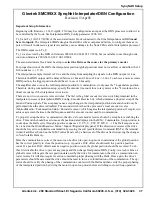
Beginning with firmware v3.14 13Apr04, TX0 may be configured as an input at the DBN processor to allow it to
be controlled by the Node. See Interpolator/DBN_Config parameter #206, bit 1
Tx_0 and Tx_1(fw 5/17/2004) of the associated motor block connected to the Sine Interpolator and DBN
must
be set to inputs.
The Interpolator/DBN daughter board drives these outputs and failure to configure them as in-
puts will result in unknown signal levels and may cause damage to the Node FPGA and/or Interpolator processor.
The DBN output is on Tx_0
Tx_1 was reserved by the DBN in firmware 9000-3411-001-B 05/17/2004, but is available to use through node
control on firmware 9000-3411-001-C 06/10/2004.
The associated motor block must be setup to
select the Drive as the source for the primary encoder
For proper function of the DBN, the interpolator position (global position) must not overflow or underflow the 32
bit boundaries (+/- 2^31).
The Interpolator sample interval is 2.0 us and the delay from sampling the signals to the DBN output is 1.4us.
Therefore the DBN output will be delayed between 1.4us and 3.4us or 2.4us +/-1.0us. To achieve a more accurate
DBN position, the trigger position should be set to occur 2.4us early.
The amplifier does not use the full interpolated position for commutation, it only uses the *4 quadrature position.
Therefore, during commutation setup, specify the encoder line count for a rotary motor or the *4 resolution for a
linear encoder as if the interpolator is not in use.
There are now two encoder reverse switches. The first is the global encoder reverse switch implemented in the
interpolator processor (Interpolator/DBN_Config, Encoder Reverse bit), which simulates a physical swap of the
Sin and Cosine signals. This swap may cause a step change in the interpolated position data and should only be
performed when the drive is disabled. The second switch is the drive processor’s local encoder reverse
(MotionMaestro->Commutation Setup->Encoder reverse,), which negates the interpolated position, if required, to
achieve agreement between the Hall sequence and the encoder counter used for commutation.
To properly setup the drive’s commutation, the drive’s local encoder reverse should be setup before enabling the
drive. This switch should be set to cause the position data displayed in the MM->Commutation_Setup window to
count up as the Halls cycle through a positive sequence ( U, UV, V, VW, W, WU, U ...). The Hall sequence can
be viewed on the MotionMaestro->Status->Inputs->Digital display panel. If the direction is reversed, the drive
should be forced to re-initialize commutation by issuing the soft reset/fault reset command (RST at the terminal
widow/Fault Reset button on the MM Control Panel) or by a hard reset of the drive after first saving the changes
to Non-Volatile Memory.
Once the commutation is correct, the motor can be driven in open-loop mode to determine if the global position
has the correct polarity to close the position loop. A positive DAC offset should result in a positive position
count. If a positive DAC offset causes a negative position count, the global position should be reversed. To do
this, first disable the drive to prevent any jumps and then change Interpolator/DBN_Config, reverse bit. Since a
global reverse will negate the raw position data used by the drive for commutation, the drive’s commutation en-
coder reverse bit will also require inversion to maintain proper phasing with the Halls. Once again, the drive’s
parameters should be saved and the drive should be reset to force a re-initialization of the commutation. The op-
erator should re-verify the phasing of the commutation counter with the Halls and then verify the proper phasing
of the interpolated position by driving the motor in open loop mode before switching to closed loop operation.
SynqNet® Setup
Summary of Contents for Omega SMC9930
Page 73: ...Glentek Inc 208 Standard Street El Segundo California 90245 U S A 310 322 3026 73 Appendix K...
Page 75: ...Glentek Inc 208 Standard Street El Segundo California 90245 U S A 310 322 3026 75 Appendix K...
Page 77: ...Glentek Inc 208 Standard Street El Segundo California 90245 U S A 310 322 3026 77...


