Glentek Inc. 208 Standard Street, El Segundo, California 90245, U.S.A. (310) 322-3026
38
Omega Series Digital PWM Amplifier Manual
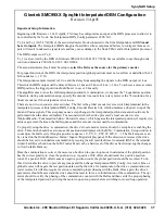
Parameters 200-207 are saved to the drive processor’s Non volatile memory upon issuance of a save command
and are written to the Interpolator processor at power on and following a hard reset. These parameters are also
written to the Interpolator processor if the
Interpolator/DBN_Mode
is set to
Setup/Cal.
All Interpolator/DBN Settings are implemented as Service Channel Drive Parameters and can be accessed using
the
meiSqNodeDriveParamSet/Get
functions.
Read-Only Status parameters (220-222) may also be read using the cyclic message, monitor channels. The moni-
tor data can be selected using the
MEISqNodeDriveMonitorConfig
and viewed using the
MEISqNodeMonitor-
Value
functions. Parameters 220-222 are located at monitor table index numbers 18-20 respectively.
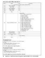
Interpolator/DBN Read/Write Parameters
Index Parameter Range Interpolator Mode
200 SineOffset -32767 to +32767 Setup/Cal
Offset correction to the encoder Sine input to calibrate signal inaccuracies for improved interpolator ac-
curacy. This parameter should be set after selecting the encoder direction since changing the encoder di-
rection swaps the sine and cosine input channels.
201 SineGain -32767 to +32767 Setup/Cal
Gain correction to the encoder Sine input to calibrate signal inaccuracies for improved interpolator accu-
racy. This parameter should be set after selecting the encoder direction since changing the encoder direc-
tion swaps the sine and cosine input channels. This parameter should be used to match the signal ampli-
tudes of the sine and cosine channels. A value of 32767 represents a gain of 1.0. The signal with the
smaller amplitude should be left with a gain of 1.0 (32767) while the signal with the larger amplitude can
be multiplied by a gain of less than 1.0 to achieve matching signal amplitudes.
Example:
Sine peak to peak = 55000 counts
Cosine peak to peak = 50000 counts then
Set Cosine gain = 32767
Set Sine gain = 32767*50000/55000 = 29788.
202 CosineOffset -32767 to +32767 Setup/Cal
Offset correction to the encoder Cosine input to calibrate signal inaccuracies for improved interpolator
accuracy. This parameter should be set after selecting the encoder direction since changing the encoder
direction swaps the sine and cosine input channels.
203 CosineGain -32767 to +32767 Setup/Cal
Gain correction to the encoder Cosine input to calibrate signal inaccuracies for improved interpolator ac-
curacy. This parameter should be set after selecting the encoder direction since changing the encoder di-
rection swaps the sine and cosine input channels. See SineGain description for more details.
204 DBN_PulseWidth 0 to 65535 Setup/Cal
Pulse output width of DBN output, 1 count = 1/75 usec
205 DBN_Interval signed32 Setup/Cal
Position interval/step size between DBN output pulses.
Summary of Contents for Omega SMC9930
Page 73: ...Glentek Inc 208 Standard Street El Segundo California 90245 U S A 310 322 3026 73 Appendix K...
Page 75: ...Glentek Inc 208 Standard Street El Segundo California 90245 U S A 310 322 3026 75 Appendix K...
Page 77: ...Glentek Inc 208 Standard Street El Segundo California 90245 U S A 310 322 3026 77...


