background image

N

OTE

:

Ensure that you note the routing of the cables as you remove them from

the system board. You must route the cables properly when you replace them to
prevent the cables from being pinched or crimped.

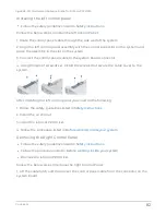
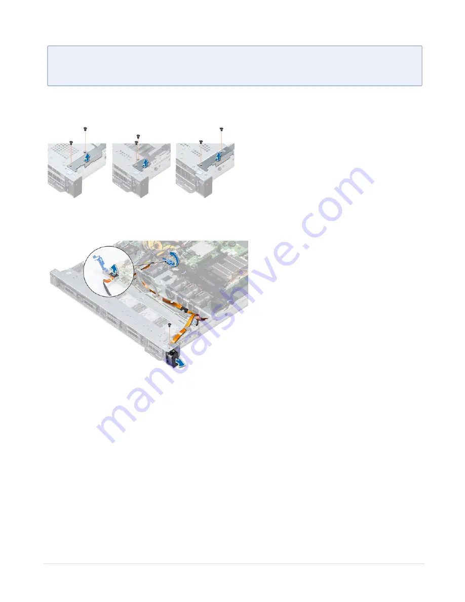
2. Using a Phillips #1 screwdriver, remove the screws that secure the cable cover to the
system.

3. Using a Phillips #1 screwdriver, remove the screw that secures the control panel to the
system.

4. Holding the control panel by its sides, remove the control panel away from the system.

Installing the right control panel

l

Follow the safety guidelines listed in

Safety instructions

.

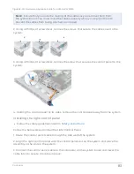
Follow the below steps to install the right Control Panel:

1. Route the control panel cable through the side wall of the system.

2. Align the right control panel with the control panel slot on the system and place the
assembly in the slot on the system.

3. Connect the control panel cable to the connector on the system board and lower the
cable latch to secure the cable in place.

Contents

83

GigaVUE-FM Hardware Appliance Guide for GFM-HW1-FM010

Summary of Contents for GFM-HW1-FM010

Page 1: ...GigaVUE FM Hardware Appliance Guide for GFM HW1 FM010 GigaVUE FM Product Version 5 15 Document Version 1 0 See Change Notes for document updates ...

Page 2: ...ibutions Gigamon and the Gigamon logo are trademarks of Gigamon in the United States and or other countries Gigamon trademarks can be found at www gigamon com legal trademarks All other trademarks are the trademarks of their respective owners Gigamon Inc 3300 Olcott Street Santa Clara CA 95054 408 831 4000 Change Notes When a document is updated the document version number on the cover page will i...

Page 3: ...g Configuration Jump Start 14 Upgrading GigaVUE FM 15 Installing and Removing System Components 18 Safety instructions 18 Before working inside your system 19 After working inside your system 19 Front Bezel Optional 20 System cover 20 Inside the System 22 Backplane Cover 23 Air Shroud 24 Cooling Fans 26 Intrusion Switch 28 Drives 29 System Memory 34 Processors and heat sinks 41 Internal PERC riser...

Page 4: ...Diagnostics 93 Embedded System Diagnostics 94 Getting Help 95 Contacting Gigamon 95 Locating your system Service Tag 95 Additional Sources of Information 96 Documentation 96 Documentation Feedback 99 Contact Technical Support 100 Contact Sales 100 The Gigamon Community 101 Glossary 102 About your system The Gigamon FM Appliance is a 1U dual socket rack system that supports Two Intel Xeon Scalable ...

Page 5: ... or DVD RW drive 3 VGA port Enables you to connect a display device to the system 4 Right control panel N A Contains the power button USB port iDRAC Direct micro port and the iDRAC Direct status LED 5 Drive slots N A Enable you to install drives that are supported on your system Left Control Panel View Item Indicator button or connector Icon Description 1 Status LED indicators N A Indicate the sta...

Page 6: ...periences an electrical error for example voltage out of range or a failed power supply unit PSU or voltage regulator Check the System event log or system messages for the specific issue If it is due to a problem with the PSU check the LED on the PSU Reseat the PSU Memory indicator The indicator turns solid amber if a memory error occurs Check the System event log or system messages for the locati...

Page 7: ...rial port to connect a serial device to the system 2 iDRAC9 dedicated network port N A Use the iDRAC9 dedicated network port to securely access the embedded iDRAC on a separate management network 3 Ethernet ports 2 Use the Ethernet ports to connect Local Area Networks LANs to the system 4 Low profile riser right slot N A Use the card slot to connect half height PCIe expansion card on low profile r...

Page 8: ...NOTE To reset iDRAC using system ID ensure that the system ID button is enabled in the iDRAC setup LCD Panel The LCD panel provides system information status and error messages to indicate if the system is functioning correctly or requires attention The LCD panel can also be used to configure or view the system s iDRAC IP address The LCD panel is available only on the optional front bezel The opti...

Page 9: ...ng when the button is released After 45 seconds of inactivity the display starts scrolling 4 LCD display Displays system information status and error messages or iDRAC IP address Viewing Home screen The Home screen displays user configurable information about the system This screen is displayed during normal system operation when there are no status messages or errors When the system turns off and...

Page 10: ...ome screen View menu NOTE When you select an option in the View menu you must confirm the option before proceeding to the next action Option Description iDRAC IP Displays the IPv4 or IPv6 addresses for iDRAC9 Addresses include DNS Primary and Secondary Gateway IP and Subnet IPv6 does not have Subnet MAC Displays the MAC addresses for iDRAC iSCSI or Network devices Name Displays the name of the Hos...

Page 11: ...to the appliance if you plan to configure the GigaVUE FM application locally 6 Power on the appliance manually if you will use the peripherals connected to the appliance to configure the GigaVUE FM application 7 Remote power on can be done through iDRAC Configuring to the GigaVUE FM You can configure the GigaVUE FM application that is pre installed on the appliance by connecting peripherals to the...

Page 12: ...u log in Accessing the Appliance Remotely You can manage the GigaVUE FM appliance remotely through iDRAC iDRAC is always available where there is power to the system This allows you to power on off the host and connect through the Integrated Remote Access Controller UI with a Web browser Before you can access the appliance remotely you need the iDRAC IP address 1 Locate the LCD display on the fron...

Page 13: ...b Enter the default username and password root admin123A c Click Submit a Enter the default username and password root admin123A NOTE It is highly recommended that you change the default password 2 The Integrated Remote Access Controller displays Contents 13 GigaVUE FM Hardware Appliance Guide for GFM HW1 FM010 ...

Page 14: ...ep in the configuration is no If you answer yes GigaVUE FM acquires the DHCP address from the local server Primary IP address and masklen Select Yes or No to mask you Primary address Default gateway Provide the default gateway address for reaching the management domain Primary DNS server Provide the default gateway address for reaching the management domain Domain name Enter a domain name to use i...

Page 15: ... start Upgrading GigaVUE FM This section describes the steps to upgrade GigaVUE You can upgrade by using an image that is located on an external image server or you can use GigaVUE FM as the image server NOTE When using the GigaVUE FM UI to upgrade GigaVUE FM you can only upgrade to the currently available version or to the next version You cannot downgrade Upgrading from an external image server ...

Page 16: ...e user name and password if you selected SCP They are not needed for TFTP c Click Save 3 Select Admin Upgrade from the GigaVUE FM header to open the FM Image Upgrade page To monitor the progress and status of the upgrade select Alarms Events Also email notifications are sent if Email Notifications have been configured For more information about Email Notifications refer to the GigaVUE FM and GigaV...

Page 17: ...de a GigaVUE FM using internal image files do the following 1 Download the images from the Gigamon website and place them where they can be available for uploading to GigaVUE FM To obtain software images register on the customer portal and download the software To reach the customer portal go to https gigamoncp forc com gigamoncp 2 Upload the images file to GigaVUE FM a Select System Images Intern...

Page 18: ...ct Alarms Events Also email notifications are sent if Email Notifications have been configured 7 Upgrade any deployed GigaVUE VMs After upgrading GigaVUE FM you must also upgrade any deployed GigaVUE VMs Otherwise maps may not work and the GigaVUE VMs will be unreachable For information about upgrading GigaVUE FM refer to GigaVUE FM and GigaVUE VM User s Guide Installing and Removing System Compon...

Page 19: ... in the system and system fans must be always populated with a component or a blank Before working inside your system 1 Follow the safety guidelines listed in Safety instructions 2 Turn off the system including all attached peripherals 3 Disconnect the system from the electrical outlet and disconnect the peripherals 4 Remove the system cover After working inside your system 1 Follow the safety gui...

Page 20: ...the LCD panel is the same Follow the safety guidelines listed in Safety instructions 1 Locate and remove the bezel key NOTE The bezel key is part of the LCD bezel package 2 Align and insert the tabs on the bezel into the slots on the system 3 Press the bezel until the button clicks in place 4 Lock the bezel by using the key System cover This describes the procedure to install and remove the System...

Page 21: ...isted in Safety instructions l Ensure that all internal cables are routed correctly and connected and no tools or extra parts are left inside the system Follow the below steps to install the System Cover 1 Align the tabs on the system cover with the guide slots on the system 2 Push the system cover latch down The system cover slides forward the tabs on the system cover engage with the guide slots ...

Page 22: ...an You should only perform troubleshooting and simple repairs as authorized in your product documentation or as directed by the online or telephone service and support team Read and follow the safety instructions that are shipped with your product 1 left control panel cable cover 2 hard drive backplane 3 backplane expander board 4 cabling latch Contents 22 GigaVUE FM Hardware Appliance Guide for G...

Page 23: ...bes the procedure to install and remove the Backplane Cover Removing the backplane cover l Follow the safety guidelines listed in Safety instructions l Follow the procedure listed in Before working inside your system l Remove the system cover Follow the below steps to remove the Backplane Cover 1 Slide the backplane cover in the direction of the arrows marked on the backplane cover 2 Lift the back...

Page 24: ...ps to install the Backplane Cover 1 Align the tabs on the backplane cover with the guide slots on the system 2 Slide the backplane cover toward the front of the system until the cover locks into place Follow the procedure listed in After working inside your system Air Shroud This describes the procedure to install and remove the Air Shroud Contents 24 GigaVUE FM Hardware Appliance Guide for GFM HW...

Page 25: ...ocedure listed in After working inside your system Installing the air shroud l Follow the safety guidelines listed in Safety instructions l Follow the procedure listed in Before working inside your system l If applicable route the cables inside the system along the system wall and secure the cables by using the cable latch Follow the below steps to install the Air Shroud 1 Align the tabs on the ai...

Page 26: ...iser l Disconnect the fan cable from the system board l Move the cables out of the way to access the cooling fan cable connector on the system board Follow the below steps to remove the Cooling Fan 1 Press the tabs on the side of the cable connector to disconnect the cable from the connector on the system board NOTE Ensure that you disconnect the fan 1 cable from the power interposer board Ensure ...

Page 27: ...l Remove the internal riser l Remove the power cable l Move the cables out of the way to access the cooling fan cable connector on the system board Follow the below steps to install the Cooling Fan 1 Holding the blue touch point place the cooling fan into the cooling fan cage 2 Route the cooling fan cable and connect it to the connector on the system board Contents 27 GigaVUE FM Hardware Appliance...

Page 28: ...ns l Follow the procedure listed in Before working inside your system l Remove air shroud l Remove internal PERC riser Follow the below steps to remove the Intrusion Switch 1 Disconnect the intrusion switch cable connected to the system board NOTE Ensure that you note the routing of the cables as you remove them from the system board 2 Slide the intrusion switch out of the intrusion switch slot In...

Page 29: ...er working inside your system Drives This describes the procedure to install and remove the Drives Removing a Drive Blank l Follow the safety guidelines listed in Safety instructions l If installed remove the front bezel CAUTION To maintain proper system cooling drive blanks must be installed in all empty drive slots CAUTION Mixing drive blanks from previous generations of PowerEdge servers is not...

Page 30: ...sh the blank until the release button clicks into place After installing the Drive blank If removed install the Front Bezel Removing a Hard Drive l Follow the safety guidelines listed in Safety instructions l If applicable remove the front bezel l Using the management software prepare the hard drive for removal If the hard drive is online the green activity or fault indicator flashes while the dri...

Page 31: ...to remove the Hard Drive 1 Press the release button to open the hard drive release handle 2 Holding the handle slide the hard drive out of the hard drive slot After removing the Hard Drive ensure the following 1 Install a hard drive 2 If you are not replacing the hard drive immediately insert a hard drive blank in the empty hard drive slot to maintain proper system cooling Installing a Hard Drive ...

Page 32: ...CAUTION When a replacement hot swappable drive is installed and the system is powered on the drive automatically begins to rebuild Ensure that the replacement drive is blank or contains data that you wish to overwrite Any data on the replacement drive is immediately lost after the drive is installed l Follow the safety guidelines listed in Safety instructions l If applicable remove the hard drive ...

Page 33: ... carriers from other generations of PowerEdge servers is not supported NOTE When installing a drive into the drive carrier ensure that the screws are torqued to 4 in lbs Follow the below steps to install the Drive from Drive Carrier 1 Insert the drive into the drive carrier with the connector end of the drive towards the back of the carrier 2 Align the screw holes on the drive with the screws hole...

Page 34: ...ur system contains 16 memory sockets Processor 1 supports up to 10 memory sockets and Processor 2 supports up to 6 memory sockets Six memory channels are allocated to each processor Processor 1 has four 2 DIMM slots per channel and two 1 DIMM slot per channel Processor 2 has six 1 DIMM per channel Memory channels are organized as follows Contents 34 GigaVUE FM Hardware Appliance Guide for GFM HW1 ...

Page 35: ...wing general guidelines when configuring your system memory If your system s memory configurations fail to observe these guidelines your system might not boot stop responding during memory configuration or operate with reduced memory System profile selected for example Performance Optimized or Custom can be run at high speed or lower Maximum supported DIMM speed of the processors Maximum supported...

Page 36: ...d by the black release tabs When mixing memory modules with different capacities populate the sockets with memory modules with the highest capacity first NOTE For example if you want to mix 8 GB and 16 GB memory modules populate 16 GB memory modules in the sockets with white release tabs and 8 GB memory modules in the sockets with black release tabs Memory modules of different capacities can be mi...

Page 37: ...trollers operate independently in the 64 bit mode and provide optimized memory performance Mirror Mode The Mirror Mode if enabled the system maintains two identical copies of data in memory and the total available system memory is one half of the total installed physical memory Half of the installed memory is used to mirror the active memory modules This feature provides maximum reliability and en...

Page 38: ...ual processor configuration with sixteen 16 GB dual rank memory modules the available system memory 16 GB x 16 memory modules 8GB 1 rank sparing channel x 12 channel 256 GB 96 GB 160 GB For multi rank sparing in a dual processor configuration with sixteen 64 GB quad rank memory modules the available system memory 64 GB x 16 memory modules 32 GB 2 rank sparing channel x 12 channel 1024 GB 384 GB 64...

Page 39: ...lowed Odd number of DIMM population is allowed NOTE NOTE Odd number of DIMMs will result in unbalanced memory configurations which in turn will result in performance loss It is recommended to populate all memory channels identically with identical DIMMs for best performance Optimizer population order is not traditional for 4 and 8 DIMM installations of single processor o For 4 DIMMs A1 A2 A4 A5 o ...

Page 40: ... amount of DIMM slots per processor allowed Odd number of DIMM population is allowed NOTE NOTE Odd number of DIMMs will result in unbalanced memory configurations which in turn will result in performance loss It is recommended to populate all memory channels identically with identical DIMMs for best performance Optimizer population order is not traditional for 8 and 14 DIMM installations of dual p...

Page 41: ...to touch for some time after the system is powered down Allow the heat sink to cool before removing it l Follow the safety guidelines listed in Safety instructions l Follow the procedure listed in Before working inside your system l If applicable remove the air shroud Removing Processor and Heat Sink Module Follow the below steps to remove a Processor and Heat Sink module 1 Using a Torx T30 screwd...

Page 42: ... heat sink to the system board and then place the processor and heat sink module PHM on the processor socket CAUTION To avoid damaging the fins on the heat sink do not press down on the heat sink fins NOTE Ensure that the PHM is held parallel to the system board to prevent damaging the components 2 Push the blue retention clips inward to allow the heat sink to drop into place 3 Using the Torx T30 ...

Page 43: ...m 1 35N m or 12 in lbf After installing the Processor Heat Sink Module follow the procedure listed in After working inside your system Removing the Processor from the Processor and Heat Sink Module NOTE Only remove the processor from the processor and heat sink module if you are replacing the processor or heat sink This procedure is not required when replacing a system board l Follow the safety gu...

Page 44: ...nstalling the Processor into a Processor and Heat Sink Module l Follow the safety guidelines listed in Safety instructions Follow the below steps to install a Processor from a Processor and Heat Sink module 1 Place the processor in the processor tray NOTE Ensure that the pin 1 indicator on the processor tray is aligned with the pin 1 indicator on the processor 2 Flex the outer edges of the bracket...

Page 45: ...cket NOTE The thermal grease syringe is intended for single use only Dispose the syringe after you use it 5 Place the heat sink on the processor and push down on the base of the heat sink until the bracket locks onto the heat sink NOTE Ensure that the two guide pin holes on the bracket match the guide holes on the heat sink Do not press on the heat sink fins Ensure that the pin 1 indicator on the ...

Page 46: ... see Cable routing l Follow the safety guidelines listed in Safety instructions l Follow the procedure listed in Before working inside your system l Remove the air shroud Follow the below steps to remove the Internal PERC Riser 1 Open the cable guiding latch for easy access 2 Lower the plunger 3 Press the cable connector and disconnect the PERC cable from the backplane 4 Hold the blue touch points...

Page 47: ...stem 3 Install the internal PERC card Installing the Internal PERC Riser NOTE The new generation PERC 11 H750 H350 and HBA350i adapters cannot be mixed with the PERC H740P H730P H330 HBA330 adapters of the previous generations in one system For more information see Cable routing l Follow the safety guidelines listed in Safety instructions Follow the below steps to install the Internal PERC Riser 1...

Page 48: ...atch to close the latch After installing the Internal PERC Riser you could do the following 1 Install the air shroud 2 Follow the procedure listed in After working inside your system Removing the PERC card from the internal PERC riser l Follow the safety guidelines listed in Safety instructions l Follow the procedure listed in Before working inside your system l Remove the air shroud l Remove the ...

Page 49: ...eplace the air shroud 3 Follow the procedure listed in After working inside your system Installing PERC card into the Internal PERC riser l Follow the safety guidelines listed in Safety instructions Follow the below steps to install the PERC card from the Internal PERC Riser 1 Insert the PERC card into the internal PERC riser and push the card in 2 Using a Phillips 2 screwdriver replace the screw ...

Page 50: ...ight riser Slot 2 Low Profile Half Length x16 Right riser Slot 2 Full Height Half Length x16 PCIe passive bridge Slot integrated Low Profile Half Length x8 Internal riser Slot integrated Low Profile Half Length x8 Left riser Slot 3 Low Profile Half Length x16 NOTE The expansion card slots are not hot swappable The following table provides guidelines for installing expansion cards to ensure proper ...

Page 51: ...s Intel 2 Full Height 10G NICs Intel 2 Full Height 25G NICs Intel 2 Full Height 40G NICs Intel 2 Full Height FC8 HBA Emulex 2 Full Height FC16 HBA Emulex 2 Full Height InfiniBand HCA FDR Mellanox 2 Full Height 10G NICs Mellanox 2 Full Height 25G NICs Mellanox 2 Full Height 40G NICs Mellanox 2 Full Height 100G NICs Mellanox 2 Full Height FC8 HBA QLogic 2 Full Height FC16 HBA QLogic 2 Full Height 10...

Page 52: ...adcom 3 Low Profile 1G NICs Intel 3 Low Profile 10G NICs Intel 3 Low Profile 25G NICs Intel 3 Low Profile 40G NICs Intel 3 Low Profile FC8 HBA Emulex 3 Low Profile FC16 HBA Emulex 3 Low Profile InfiniBand HCA FDR Mellanox 3 Low Profile 10G NICs Mellanox 3 Low Profile 25G NICs Mellanox 3 Low Profile 40G NICs Mellanox 3 Low Profile 100G NICs Mellanox 3 Low Profile FC8 HBA QLogic 3 Low Profile FC16 H...

Page 53: ...ow Profile 1G NICs Intel 3 2 Low Profile 10G NICs Intel 3 2 Low Profile 25G NICs Intel 3 2 Low Profile 40G NICs Intel 3 2 Low Profile FC8 HBA Emulex 3 2 Low Profile FC16 HBA Emulex 3 2 Low Profile InfiniBand HCA FDR Mellanox 3 2 Low Profile 10G NICs Mellanox 3 2 Low Profile 25G NICs Mellanox 3 2 Low Profile 40G NICs Mellanox 3 2 Low Profile 100G NICs Mellanox 3 2 Low Profile FC8 HBA QLogic 3 2 Low...

Page 54: ...rofile 1G NICs Intel 2 Low Profile 10G NICs Intel 2 Low Profile 25G NICs Intel 2 Low Profile 40G NICs Intel 2 Low Profile FC8 HBA Emulex 2 Low Profile FC16 HBA Emulex 2 Low Profile InfiniBand HCA FDR Mellanox 2 Low Profile 10G NICs Mellanox 2 Low Profile 25G NICs Mellanox 2 Low Profile 40G NICs Mellanox 2 Low Profile 100G NICs Mellanox 2 Low Profile FC8 HBA QLogic 2 Low Profile FC16 HBA QLogic 2 L...

Page 55: ...ard riser configurations Expansion card riser PCIe slots on the riser Height Length Link LOM riser Slot 1 Mezz type Mezz type x8 Right riser Slot 2 Low Profile Half Length x16 Right riser Slot 2 Full Height Half Length x16 PCIe passive bridge Slot integrated Low Profile Half Length x8 Internal riser Slot integrated Low Profile Half Length x8 Left riser Slot 3 Low Profile Half Length x16 Installing...

Page 56: ...uld do the following 1 Follow the procedure listed in After working inside your system 2 Install any device drivers required for the card as described in the documentation for the card Contents 56 GigaVUE FM Hardware Appliance Guide for GFM HW1 FM010 ...

Page 57: ...sted in Before working inside your system l Disconnect any cables connected to the expansion card Follow the below steps to remove an Expansion Card Riser Hold the touch points and lift the expansion card riser from the riser connector on the system board Contents 57 GigaVUE FM Hardware Appliance Guide for GFM HW1 FM010 ...

Page 58: ...n Card Riser 1 Open the PCIe card holder latch 2 Hold the expansion card by its edges and pull the card until the card edge connector disengages from the expansion card connector on the riser 3 Install a filler bracket if you are not replacing the expansion card NOTE You must install a filler bracket over an empty expansion card slot to maintain Federal Communications Commission FCC certification ...

Page 59: ...nying the card l Remove the expansion card riser Follow the below steps to install an Expansion Card from the Expansion Card Riser 1 Open the PCIe card holder latch 2 If installed remove the filler bracket NOTE Store the filler bracket for future use Filler brackets must be installed in empty expansion card slots to maintain Federal Communications Commission FCC certification of the system The bra...

Page 60: ...nector with the expansion card connector on the riser 4 Insert the card edge connector firmly into the expansion card connector until the card is fully seated 5 Close the expansion card latch Contents 60 GigaVUE FM Hardware Appliance Guide for GFM HW1 FM010 ...

Page 61: ... 2 SSD module NOTE The write protect switch is on the IDSDM or vFlash module Installing the M 2 SSD module l Follow the safety guidelines listed in Safety instructions l Remove the air shroud l Remove the BOSS card NOTE The procedure to remove the BOSS card is similar to the removing an expansion card Follow the below steps to install a M 2 SSD module 1 Connect the M 2 SSD module to the connector ...

Page 62: ...es listed in Safety instructions l Follow the procedure listed in Before working inside your system l Remove the air shroud l Remove the BOSS card NOTE The procedure to remove the BOSS card is similar to the removing an expansion card Follow the below steps to remove a M 2 SSD module 1 Loosen the screw and lift the retention strap that secures the M 2 SSD module on the BOSS card 2 Lift the M 2 SSD...

Page 63: ...the procedure listed in Before working inside your system Follow the below steps to remove a MicroSD card 1 Locate the MicroSD card slot on the vFlash IDSDM module and press the card to partially release it from the slot To locate IDSDM vFlash module see the System board jumpers and connectors section 2 Hold the MicroSD card and remove it from the slot Contents 63 GigaVUE FM Hardware Appliance Gui...

Page 64: ...icroSD cards into the same slots based on the labels you had marked on the cards during removal Follow the below steps to install a MicroSD card 1 Locate the MicroSD card connector on the IDSDM vFlash module Orient the MicroSD card appropriately and insert the contact pin end of the card into the slot To locate IDSDM vFlash see the System board jumpers and connectors section NOTE The slot is keyed...

Page 65: ...Flash connector on the system board To locate IDSDM vFlash connector see the System board jumpers and connectors section 2 Holding the pull tab lift the IDSDM vFlash card out of the system NOTE There are two dip switches on the IDSDM vFlash card for write protection After removing the IDSDM vFlash card you could do the following 1 Install the optional IDSDM vFlash card Installing optional IDSDM or...

Page 66: ...re listed in After working inside your system LOM riser card Removing the LOM riser card l Follow the safety guidelines listed in Safety instructions l Follow the procedure listed in Before working inside your system l If installed remove the risers Follow the below steps to remove the LOM riser card 1 Using a Phillips 2 screwdriver loosen the screws that secure the LOM riser card to the system bo...

Page 67: ...to install the LOM riser card 1 Align the connectors on the LOM riser card with the slot on the system 2 Press the LOM riser card until the card is firmly seated on the system board connector and the two blue plastic snap hold the LOM riser card in place 3 Using a Phillips 2 screwdriver replace the screws to secure the LOM riser card to the system board After installing the LOM riser card you coul...

Page 68: ...onnector 6 backplane power cable connector Installing the hard drive backplane l Follow the safety guidelines listed in Safety instructions NOTE The procedure to install the backplane is similar for all backplane configurations Follow the below steps to install the hard drive backplane 1 Align the slots on the backplane with the hooks on the system 2 Lower the hard drive backplane until the blue r...

Page 69: ...ve the hard drives from the system before removing the backplane CAUTION Note the number of each hard drive and temporarily label them before you remove the hard drive so that you can replace them in the same location NOTE NOTE The procedure to remove the backplane is similar for all backplane configurations l Follow the safety guidelines listed in Safety instructions l Follow the procedure listed...

Page 70: ...ane from the hooks on the system 2 To remove a backplane with an expander board a Loosen the captive screws that secure the expander board a Press the release tabs and lift the backplane to disengage the slots on the backplane from the hooks on the system 3 Lift the backplane out of the system Cable Routing Cable routing 8 x 2 5 hard drive backplane with PERC riser Contents 70 GigaVUE FM Hardware ...

Page 71: ...interposer board 7 Internal PERC 8 System board Cable routing 8 x 2 5 hard drive backplane with onboard SATA 1 hard drive backplane 2 backplane power cable 3 SATA cable BP SATA_B to MB 4 SATA cable BP SATA_A to MB 5 backplane signal cable 6 cable routing clip 7 power interposer board 8 system board Contents 71 GigaVUE FM Hardware Appliance Guide for GFM HW1 FM010 ...

Page 72: ...Before working inside your system l If applicable disconnect the power or data cables from expansion card s Follow the below steps to remove and install the System Battery 1 Locate the battery socket For more information see the Jumpers and Connectors section CAUTION To avoid damage to the battery connector you must firmly support the connector while installing or removing a battery 2 Use a plasti...

Page 73: ...nal USB memory key CAUTION To avoid interference with other components in the server the maximum permissible dimensions of the USB memory key are 15 9 mm wide x 57 15 mm long x 7 9 mm high l Follow the safety guidelines listed in Safety instructions l Follow the procedure listed in Before working inside your system Follow the below steps to replace the optional Internal USB Memory Key 1 Locate the...

Page 74: ...nd drive Route these cables properly when you replace them to prevent them from being pinched or crimped Follow the below steps to remove the optional Optical Drive 1 Press the release tab to release the optical drive 2 Slide the optical drive out of the system until it is out of the optical drive slot 3 If you are not adding a new optical drive install the optical drive blank The procedure to ins...

Page 75: ...SUs from previous generations of PowerEdge servers is not supported even if the PSUs have the same power rating Mixing PSUs will result in mismatch condition or failure to turn the system on NOTE When two identical PSUs are installed power supply redundancy 1 1 with redundancy or 2 0 without redundancy is configured in system BIOS In redundant mode power is supplied to the system equally from both...

Page 76: ...ank l Follow the safety guidelines listed in Safety instructions NOTE Install the power supply unit PSU blank only in the second PSU bay Follow the below steps to install the Power Supply Unit blank 1 Align the PSU blank with the PSU slot and push it into the PSU slot until it clicks into place After installing a Power Supply Unit follow the procedure listed in After working inside your system Rem...

Page 77: ...e latch and slide the PSU out of the system by using the PSU handle Installing a Power Supply Unit l Follow the safety guidelines listed in Safety instructions l For systems that support redundant PSU ensure that both the PSUs are of the same type and have the same maximum output power NOTE The maximum output power shown in watts is listed on the PSU label Follow the below steps to install the Pow...

Page 78: ...redundant cabled AC power supply unit l Follow the safety guidelines listed in Safety instructions l Follow the procedure listed in Before working inside your system l Remove the air shroud l Disconnect the system from the electrical outlet l Disconnect all the cables connected from the PSU to the system board l If applicable remove the expansion card riser Follow the below steps to remove a non r...

Page 79: ... system Power interposer board Removing power interposer board l Follow the safety guidelines listed in Safety instructions l Follow the procedure listed in Before working inside your system l Remove the air shroud l Disconnect all the cables connected from the PIB to the system board NOTE Ensure that you note the routing of the cables as you remove them from the system board l Remove the PSU Foll...

Page 80: ... Interposer Board 1 Align the slots on the PIB with the guides on the system 2 Using a Phillips 2 screwdriver replace the two screws to secure the PIB to the system 3 Route the cables and connect it to the system board After installing the Interposer Board you could do the following 1 Install the PSU 2 Install the air shroud 3 Follow the procedure listed in After working inside your system Content...

Page 81: ...board connector NOTE Ensure that you note the routing of the cables as you remove them from the system board You must route the cables properly when you replace them to prevent the cables from being pinched or crimped 2 Using a Phillips 1 screwdriver remove the screws that secure the cable cover 3 Using a Phillips 1 screwdriver remove the screws that connect the control panel to the system 4 Holdi...

Page 82: ...over to the system After installing the left control panel you could do the following 1 Follow the safety guidelines listed in Safety instructions 2 Install the air shroud 3 Install the internal PERC riser 4 Follow the procedure listed in Before working inside your system Removing the Right Control Panel l Follow the safety guidelines listed in Safety instructions l Follow the procedure listed in ...

Page 83: ...ntrol panel by its sides remove the control panel away from the system Installing the right control panel l Follow the safety guidelines listed in Safety instructions Follow the below steps to install the right Control Panel 1 Route the control panel cable through the side wall of the system 2 Align the right control panel with the control panel slot on the system and place the assembly in the slo...

Page 84: ... key when you restart your system or program before you can access the encrypted data on your hard drives CAUTION Do not attempt to remove the TPM plug in module from the system board Once the TPM plug in module is installed it is cryptographically bound to that specific system board Any attempt to remove an installed TPM plug in module breaks the cryptographic binding and it cannot be re installe...

Page 85: ...ystem board by holding a memory module processor or other components 2 Using a Phillips 2 screwdriver remove the screws that secure the system board to the chassis 3 Hold the system board holder slightly lift the system board and then slide it toward the front of the chassis 4 Using the system board holder lift the system board out of the chassis Installing the System Board l Follow the safety gui...

Page 86: ...ps 2 screwdriver replace the screws that secure the system board to the chassis After installing the system board you could do the following 1 Replace the following a Install the Trusted Platform Module TPM b Internal PERC riser c Internal USB key if applicable d USB 3 0 module if applicable e IDSDM vFlash module card f All expansion cards and risers g Processors and heat sink modules h Processors...

Page 87: ...license Restoring the system using Easy Restore The easy restore feature enables you to restore your service tag license UEFI configuration and the system configuration data after replacing the system board All data is backed up in a backup flash device automatically If BIOS detects a new system board and the service tag in the backup flash device BIOS prompts the user to restore the backup inform...

Page 88: ...rect service tag Once the service tag is entered it cannot be updated or changed 5 Click OK Entering the system Service Tag by using System Setup If Easy Restore fails to restore the Service Tag use System Setup to enter the Service Tag Follow the below steps 1 Turn on the system 2 Press F2 to enter System Setup 3 Click Service Tag Settings 4 Enter the Service Tag NOTE You can enter the Service Ta...

Page 89: ...art your system or program before you can access the encrypted data on your hard drives CAUTION Once the TPM plug in module is installed it is cryptographically bound to that specific system board Any attempt to remove an installed TPM plug in module breaks the cryptographic binding the removed TPM cannot be reinstalled or installed on another system board Removing the TPM To remove the TPM follow...

Page 90: ...the TPM l The TPM Status changes to Enabled Activated Initializing the TPM 1 2 for TXT users Follow the below steps to initialize the TPM 1 While booting your system press F2 to enter System Setup 2 On the System Setup Main Menu screen click System BIOS System Security Settings 3 From the TPM Security option select On with Pre boot Measurements 4 From the TPM Command option select Activate 5 Save ...

Page 91: ...fan 6 connector 2 CPU1 Processor socket 1 3 CPU1_PWR_CONN P2 CPU1 power connector 4 J_INTRU Intrusion switch connector 5 J_BP_SIG1 Backplane signal connector 1 6 LFT_CP_CONN Left control panel connector 7 J_SATA_B1 Internal SATA B connector 8 RGT_CP_CONN Right panel connector 9 SYS_PWR_CONN P1 System power connector 10 J_PIB_SIG1 Power interposer board signal connector 1 11 J_PIB_SIG2 Power interp...

Page 92: ...CIE_A0 NVMe connector 34 CPU2_PWR_CONN P3 CPU2 power connector System board jumper settings For information on resetting the password jumper to disable a password see the Disabling a forgotten password section Disabling forgotten password The software security features of the system include a system password and a setup password The password jumper enables or disables password features and clears ...

Page 93: ...tem including any attached peripherals 6 Power off the system including any attached peripherals and disconnect the system from the electrical outlet 7 Remove the system cover 8 Move the jumper on the system board jumper from pins 4 and 6 to pins 2 and 4 9 Install the system cover 10 Reconnect the system to its electrical outlet and power on the system including any attached peripherals 11 Assign ...

Page 94: ... device in the system does not operate properly running the embedded system diagnostics may indicate component failure Running the Embedded System Diagnostics from Boot Manager 1 As the system boots press F11 2 Use the up and down arrow keys to select System Utilities Launch Diagnostics STEP RESULT The ePSA Pre boot System Assessment window is displayed listing all devices detected in the system T...

Page 95: ...ur purchase invoice packing slip bill or product catalog Availability varies by country and product and some services may not be avail able in your area To contact Gigamon for sales technical support or customer service issues 1 For support go to gigamon com support and services contact support 2 For sales inside sales gigamon com or 1 408 831 4025 Locating your system Service Tag Your system is i...

Page 96: ... for a release in common folder you can easily search across the doc set by opening one of the files in Acrobat and choosing Edit Advanced Search from the menu This opens an interface that allows you to select a directory and search across all PDFs in a folder Hardware how to unpack assemble rack mount connect and initially configure ports the respective GFM HW1 FM010 devices reference information...

Page 97: ...e for VMware GigaVUE V Series Guide GigaVUE Cloud Suite for AnyCloud Guide GigaVUE Cloud Suite for Kubernetes Guide GigaVUE Cloud Suite for Nutanix Guide GigaVUE Cloud Suite for VMware GigaVUE VM Guide GigaVUE Cloud Suite for AWS Secret Regions Guide Reference GigaVUE OS CLI Reference Guide library of GigaVUE OS CLI Command Line Interface commands used to configure and operate GigaVUE H Series and...

Page 98: ...Registered Customers can download software and corresponding Release Notes documents from the Software Release Notes page on to My Gigamon Use the My Gigamon Software Docs page to download l Gigamon Software installation and upgrade images l Release Notes for Gigamon Software or l Older versions of PDFs pre v5 7 To download release specific software release notes or older PDFs 1 Log in to My Gigam...

Page 99: ...n as possible Documentation Feedback Form About You Your Name Your Role Your Company For Online Topics Online doc link URL for where the issue is Topic Heading if it s a long topic please provide the heading of the section where the issue is For PDF Topics Document Title shown on the cover page or in page header Product Version shown on the cover page Document Version shown on the cover page Chapt...

Page 100: ...upport at support gigamon com Contact Sales Use the following information to Gigamon channel partner or Gigamon sales representatives Telephone 1 408 831 4025 Sales inside sales gigamon com Partners www gigamon com partners html Premium Support Email Gigamon at inside sales gigamon com for information on purchasing 24x7 Premium Support Premium Support entitles you to round the clock phone support ...

Page 101: ...oration around a technology use case vertical market or beta release Take online learning lessons and tutorials to broaden your knowledge of Gigamon products Submit and vote on feature enhancements and share product feedback Customers only Open support tickets Customers only Download the latest product updates and documentation Customers only The Gigamon Community is a great way to get answers fas...

Page 102: ...p formerly blacklist F forward list selective forwarding forward formerly whitelist L leader leader in clustering node relationship formerly master M member node follower in clustering node relationship formerly slave or non master N no decrypt list no need to decrypt formerly whitelist Glossary 102 GigaVUE FM Hardware Appliance Guide for GFM HW1 FM010 ...

Page 103: ...iming transmits sync info to clocks in its network segment formerly grandmaster R receiver follower in a bidirectional clock relationship formerly slave S source leader in a bidirectional clock relationship formerly master Glossary 103 GigaVUE FM Hardware Appliance Guide for GFM HW1 FM010 ...

Reviews: