background image


ProfiLux 4 Resource Guide


EN

   2018-13-11                                                                                                                               

85


How to setup Maintenance modes 

ProfiLux 4 can be configured to temporarily shut down specific outlets, 1-10V devices, and 
Mitras Lightbar. This feature is especially useful for manual water changes or general 
maintenance tasks. When activated, specific devices will be turned OFF for a certain amount of 
time, then turned back ON after the time has elapsed. 


TIP 

You can have up to 4 different maintenance modes. 


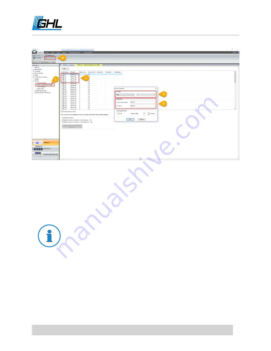
To setup Maintenance mode, please follow these steps: 

1.


Click on the (+) icon to the left of 

Extras

 and select a MAINTEANCE option. 

2.


Select which Powerbar outlets you want to react to the selected MAINTENANCE mode. 


Select the desired outlets, then set them to either turn ON or turn OFF when this 
Maintenance mode is activated. 

3.


If you have 1-10V devices, select which device you want to react and the percentage it 
shall run at when Maintenance mode is activated. 

4.


If you have a Mitras Lightbar, select which channel will react and the percentage. 

5.


Type-in a description for this maintenance mode. 

Summary of Contents for ProfiLux 4

Page 1: ...ProfiLux 4 Resource Guide Step by step resource guide for ProfiLux 4 As of November 2018...

Page 2: ...ROL CENTER 10 GCC START SCREEN 11 GCC TABS DEVICES 12 GCC TABS VIEW 13 GCC TABS HELP 13 GCC TABS TOOLS 13 GCC TABS EXTRAS 14 GCC TABS BACKUP AND RESTORE 14 GCC TABS COMMUNICATION 15 TO DO CONNECT VIA...

Page 3: ...OL 59 TO DO SETUP RETURN PUMP CONTROL 62 REACT TO A FEED PAUSE 63 SHUT DOWN PUMP IF SUMP WATER LEVEL GETS TOO LOW 63 COMBINE FEED PAUSE AND LEAKAGE DETECTION 63 CONTROL FLOW RATE VIA 1 10V INTERFACE 6...

Page 4: ...E PROFILUX 4 FIRMWARE 101 HOW TO UPDATE PROFILUX 4 WI FI MODULE WEB SERVER WEB INTERFACE 105 HOW TO UPDATE PAB DEVICE FIRMWARE 107 PROGRAMMABLE LOGIC EXAMPLES 110 HOW TO DELAY A SKIMMER FROM TURNING O...

Page 5: ...we recommend you read both our Programming Guide and Instruction Manual Doing so will provide you with the most profound details for using our product These documents can be downloaded from our websit...

Page 6: ...ult for safety reasons Digital light interface For connecting Mitras Lightbar LEDs Green Purple ports For connecting level sensors such as GHL Flow sensors float optical sensors leak interface for lea...

Page 7: ...ttings page Wi Fi module firmware GHL Control Center Communications settings page bottom right of screen myGHL General settings page GHL Connect General settings page Understanding the meaning of the...

Page 8: ...ure that all parts are included The list of included parts are shown on the product box Find a suitable spot for your ProfiLux 4 Connect all your probes to the correct BNC ports Each port is labeled s...

Page 9: ...unds to be muted 6 Confirm language in the next screen by selecting JA TO DO Install GHL Control Center Please visit our website s downloads page to download GHL Control Center This is the PC Software...

Page 10: ...o add the P4 to your existing Wi Fi network With this connection option you can connect to the P4 over your Wi Fi network via GHL Control Center or the GHL Connect app ProfiLux Webserver Allows you to...

Page 11: ...are updates setup basic and advanced functions assign devices and more GCC Start Screen This is the screen you will see when you open up GHL Control Center for the first time A This window is basicall...

Page 12: ...n NAVIGATION PANE OPTIONS GCC Tabs Devices The Devices tab is used for connecting to a GHL device Here is where you can also add a new GHL device connection or modify an existing one The UPDATE VIEW a...

Page 13: ...enable Expert mode Enabling this option will show you every available option in GCC Recommended Start window Check the box to display the GHL CONTROL CENTER START window GCC Tabs Help This tab provid...

Page 14: ...Click here to update the firmware on your P4 controller WiFi Module update Click here to update the Wi Fi module firmware for your P4 Serial number Click here to display your device serial number Keys...

Page 15: ...le to ProfiLux Click here to load your ProfiLux settings and or sensor data from a file GCC Tabs Communication This tab is useful for those who have multiple ProfiLux controllers on a single network o...

Page 16: ...ary driver https youtu be 5arEm807628 1 Using the USB cable included in the box connect one end to the PC and other end to the ProfiLux 2 Open GHL Control Center and select ProfiLux 4 on the lower lef...

Page 17: ...ow you how to configure the P4 s Wi Fi settings using Automatic IP and Static IP assignment methods Follow the instructions for your IP address assignment method of choice NOTE The P4 s WiFi module ca...

Page 18: ...pot Need a visual You can view our Wi Fi setup how to video by clicking the link below Auto IP Wi Fi Setup https youtu be AyHJoXlkJAo Static IP Wi Fi Setup https youtu be 3Rn9xMo76lk Wi Fi Auto IP Set...

Page 19: ...i Fi network 9 Reconnect via USB go to the Communication settings page and note the IP address that has been assigned to the ProfiLux 4 Wi Fi Static IP Setup 1 Using the USB cable included in the box...

Page 20: ...bers must match the first 3 set of numbers of the Gateway Subnet Mask Found in your network details Gateway Found in your network details also the IP address of your router DNS IP address of the DNS u...

Page 21: ...p the P4 s Wi Fi hotspot settings NOTE In order for the P4 to emit its own hotspot signal you must be sure to have either Access point or Client AP mode selected If you already have your P4 connected...

Page 22: ...down in step 2 How to connect to the P4 via Wi Fi This section will show you how to wirelessly connect to your ProfiLux controller AFTER you ve added it to your Wi Fi network REQUIRED P4 must be on y...

Page 23: ...ATE see top right of screen 2 Click NEW then select the ProfiLux 4 3 Set type of connection to NETWORK type in the IP address of your ProfiLux 4 give this connection a name i e ProfiLux 4 Wi Fi click...

Page 24: ...4 then press ADD 4 Select your newly made connection to connect to the P4 over Wi Fi How to setup myGHL cloud access Easily access control your ProfiLux 4 from anywhere in the world via the cloud with...

Page 25: ...follow these steps 1 Connect to your ProfiLux 4 via USB Wi Fi is also okay 2 Click on the icon right beside System and select COMMUNICATION 3 Enable myGHL select preferred option Read only Grants lim...

Page 26: ...the Security key field on myGHL com The security key shown in your GHL Control Center will be automatically generated from the myGHL servers and is only shown once your device has been verified 8 Giv...

Page 27: ...overview of the available options you will see when you are connected to the ProfiLux 4 For details not covered in this section please refer to the P4 Programming Guide As soon as you connect to the P...

Page 28: ...OUTLETS option which is used for assigning functions to specific Powerbar sockets B Basic information such as current firmware version device serial number and controller language can be seen here C...

Page 29: ...rmation on Illumination channels please refer to page 19 of the ProfiLux 4 Programming Guide A This is where you select if the lighting fixture you ll use is dimmable or not dimmable and if this chann...

Page 30: ...ys of the week to enable the Thunderstorm effect You can also specify how many times to trigger the effect the time it will occur and duration B These are the random Thunderstorm settings and manual T...

Page 31: ...hese features can be used by ProfiLux compatible dimmable lighting fixtures NOTE More information on cloud cover moon phase and rainy days can be found on page 24 of the ProfiLux 4 Programming Guide A...

Page 32: ...should react to the Rainy Day simulation TIP You can selectively choose which Illumination channel will respond to the simulations by going to the desired Illumination channel and checking the corresp...

Page 33: ...ures here is where you select when the fixture will shut off TIP You can selectively choose which Illumination channel will respond to this function by going to the desired Illumination channel and ch...

Page 34: ...f you start the acclimation feature at 50 the LED output overall will be run at 50 of the max allowed output on the Illumination channels B Shows a visual of the light output increase over the course...

Page 35: ...re you assign what days to run the selected timer You have two options to choose from Specific days of week Select days of week to run this timer Day interval Select the day intervals to run this time...

Page 36: ...edia water change etc A Double click on a reminder number to open up the editing window B Here is where you can enter the details for the selected reminder Dose overview This page shows an overview of...

Page 37: ...the fluid monitoring icon for a specific pump will bring you to that pump s settings page Dose overview Dosing pump Part 1 This is where you can setup and configure dosing pump scheduling These chann...

Page 38: ...NOTE For normal dosing purposes select Container is emptied C Dosing pump calibration settings are shown here The Flow rate of the pump field is where you enter how many ml the pump dispenses in one...

Page 39: ...eact based on the function that is assigned to a specific Powerbar outlet index corresponds to the Powerbar socket number For example if you wanted to run a Doser 2 1 as an ATO pump this option would...

Page 40: ...he dosing schedule For example if the doser should dose every 2 days set Repeat all to 2 The Starting in option is a dosing schedule delay With this option the schedule can be created today and set to...

Page 41: ...eck the box if you want to shut down an assigned Powerbar socket WHEN this feed pause is activated Duration Feedpause Type in how long the feed pause will be Timer activates Select if you want this fe...

Page 42: ...for when this mode is activated C Here is where you can use this maintenance mode for the Powercut Monitoring feature D Type in a description for this maintenance mode E Type in how long this mainten...

Page 43: ...unction at 7 2 and deactivate the function when pH goes back to 7 0 ii More information on Hysteresis can be found on page 45 of the P4 Programming guide 1 10v is max at deviation Applies to temperatu...

Page 44: ...of the ProfiLux 4 or to an expansion card that has a built in Level port Each port supports up to two separate sensors Two sensors can be used when you use a GHL splitter cable PL 0081 PL LY A This i...

Page 45: ...ater level the Powerbar socket with the function Fill Water is turned ON When normal water level is reached the socket will turn OFF Water change Two sensors are used to perform water changes When a w...

Page 46: ...of Level sensors that are assigned to specific Control circuits If there is an X marked it indicates that the sensor is currently active C This section allows you to change the behavior of specific se...

Page 47: ...to display on the ProfiLux 4 B Select when to show time date and duration of each screen C If you want to customize the text shown on start up type it in here D Select how bright you want the display...

Page 48: ...r assigning new PAB devices The System reset option is used for deleting all PAB devices assigned to the ProfiLux 4 C Specifications for the selected device will be shown here System Communication All...

Page 49: ...webserver C Wi Fi module settings are configured here D Wi Fi network settings for home network and P4 direct connection settings are configured here E Wi Fi module status such as module firmware ver...

Page 50: ...o assign type in a description set a Blackout delay if needed click OK Blackout delay In case of a power outage you can individually set each socket to turn back ON after a period of time after the po...

Page 51: ...ing up the options for that channel Email notification ProfiLux ProfiLux 4 can be configured to send email notifications under various conditions such as triggered alarms and regular emails with probe...

Page 52: ...name here My email address Enter your email address here Username Enter your email address here Password Enter your email password here TO DO Assign PAB devices to the ProfiLux 4 This section will sh...

Page 53: ...ere is how to do this 1 Connect PAB devices to P4 and power ON if applicable 2 Press up or down arrow key select SYSTEM 3 Select CONFIGURE PAB select ASSIGN DEVICES 4 Press right arrow to select devic...

Page 54: ...he ProfiLux 4 and go back to the SYSTEM settings page Clicking on the next to PAB will show the newly added PAB device NOTE If this is your FIRST Powerbar5 1 or FIRST GHL Doser 2 1 Slave the socket an...

Page 55: ...uire calibration The temperature probe for example is the only probe from the P4 set which does not require any calibration NOTE Probe calibration can be done through the ProfiLux 4 display No need to...

Page 56: ...value 1 The calibration fluid value of the first fluid that will be used Calibration value 2 The calibration fluid value of the second fluid that will be used o For example if you calibrate a pH probe...

Page 57: ...9 Wipe the probe and put it back into the aquarium Redox probe calibration In order to proceed with Redox probe calibration you will need the following fluid 220mV calibration fluid IMPORTANT Null pl...

Page 58: ...eps select YES to save calibration 9 Wipe probe and put back into the aquarium Conductivity probe calibration In order to proceed with Conductivity probe calibration you will need the following Requir...

Page 59: ...ar old 5 Select 50mS for CALIBRA VALUE 2 6 Select if the calibration process will use the temperature compensation readings from a temperature probe or a manually input temperature value 7 Enter the e...

Page 60: ...EATING THE FUNCTION 1 Connect to the ProfiLux 4 using GHL Control Center 2 Click on the icon to the left of Probe sensor controls and select the desired TEMPERATURE probe 3 Set the desired measurement...

Page 61: ...u want to turn OFF your heater when the temp reading goes outside the allowed deviation select YES for Deactivate control ASSIGNING THE FUNCTION 1 Click on the icon to the left of System 2 Select SWIT...

Page 62: ...he same TEMPERATURE HEATER function assigned Heaters and the Powerbar5 1 S5 outlet When choosing the outlet to connect your heater to keep in mind that the S5 outlet on the Powerbar5 1 has a MAX 2A ra...

Page 63: ...outlet See How to setup feed pause functions and ONLY follow CREATING THE FUNCTION steps See How to setup leakage detection and ONLY follow CREATING THE FUNCTION steps See Combining Feed Pause and Lea...

Page 64: ...d a GHL float or optical sensor This sensor is what will trigger the pump to turn OFF See How to setup leakage detection Plug in skimmer to the assigned Powerbar outlet React to a maintenance mode The...

Page 65: ...THE FUNCTION steps See Combining Feed Pause and Leakage Detection Plug in skimmer to the assigned Powerbar outlet TO DO Setup non dimmable lighting timers If you have any non dimmable lighting you wou...

Page 66: ...his feature comes in handy for those running T5 or MH lighting Temp Dep Light red will be covered in this section To setup non dimmable lighting timers please follow these steps CREATING THE FUNCTION...

Page 67: ...u created the function on Illumination channel 1 set the function to ILLUMINATION 1 If Illumination channel 2 was used set the function to ILLUMINATION 2 etc 5 Type in a description in both fields set...

Page 68: ...LLUMINATION channel 2 Check the box TEMP DEP LIGHT REDUCTION 3 Repeat steps 1 and 2 if you want multiple Illumination channels to react to this feature 4 Under the Illumination drop down list select T...

Page 69: ...ER options located under Processes NOTE TIMER functions can be used for various purposes such as running a skimmer or ozone generator during certain times of the day You can also use a normal ON OFF t...

Page 70: ...ER function to turn ON and turn OFF 6 Click SAVE CHANGES ASSIGNING THE FUNCTION 1 Click on the icon to the left of System 2 Select SWITCH CHANNELS AND OUTLETS 3 Select the outlet that you want to assi...

Page 71: ...lighting control cable to the fixture and GHL accessory then you will connect the GHL accessory to the P4 With the cables connected you will then assign the 1 10V interface function and configure your...

Page 72: ...L1 L6 for initial programming Once programming is complete you can connect this device to any L channel port If you are not using any of these accessories proceed to the next step i LEDControl4 models...

Page 73: ...iption set the output signal to 1 10V and click OK 5 Repeat steps 2 4 for each lighting channel that needs to be assigned CREATING A DIMMABLE LIGHT SCHEDULE 1 Click on the icon to the left of Illumina...

Page 74: ...ply selected the desired Illumination channel and clicking the drop down box OPTIONAL Temperature Dependent Light Reduction NOTE ProfiLux 4 can further assist with temperature management when you use...

Page 75: ...umination drop down list select TEMP DEP LIGHTRED 5 Select the Temperature probe that will be responsible for controlling the assigned Illumination channel s 6 Set the SHUT OFF LIMIT The number you se...

Page 76: ...le is not available from the pump manufacturer or there is only an RJ 45 control cable available you can still connect it to the P4 by cutting the end of the cable and connecting it to our 1 10V break...

Page 77: ...example if you have a PLM 4L interface expansion card the L channel numbering would be L7 L8 for the first port L9 L10 for the second port ii If you do not have any L channel expansion cards on the P4...

Page 78: ...dule by selecting another Stream group 2 In the Pump assignment section select the pump number you wish to assign to this Stream group Click the Left pointing arrow to assign the pump to the group 3 D...

Page 79: ...to set the min max flow to the same value to maintain consistent flow If you are running a closed loop pump Tunze Stream or another flow pump we recommend you take a look at the descriptions of the av...

Page 80: ...the link below and assign the doser to the P4 Assign PAB devices to the ProfiLux 4 Once the doser has been assigned you can proceed with the steps below Have a traditional doser If you plan to contro...

Page 81: ...dispensed and enter this amount into the Flowrate of the pump box 5 Click SAVE CHANGES To setup dosing pump schedules please follow the steps shown in this video How to create a dose schedule w GHL C...

Page 82: ...of the reminder 7 Type in a description for this reminder and click OK 8 Click SAVE CHANGES Every time a reminder event occurs the given text will be shown on the ProfiLux 4 display How to setup Feed...

Page 83: ...N 1 Click on the icon to the left of Extras and select FEED PAUSE 2 Select a Feed pause and specify the FP duration by clicking 3 times in the Duration Feedpause Min column 3 If you d like to have thi...

Page 84: ...CTION 1 Click on the icon to the left of System 2 Select SWITCH CHANNELS AND OUTLETS 3 Select the Powerbar outlet s that you d like to react to this FP 4 Set the function to FILTER and select the FILT...

Page 85: ...4 different maintenance modes To setup Maintenance mode please follow these steps 1 Click on the icon to the left of Extras and select a MAINTEANCE option 2 Select which Powerbar outlets you want to r...

Page 86: ...u will assign the function to an outlet on your GHL Powerbar In order to setup ATO control you will need certain items These items can be purchased at your preferred GHL dealer ATO w 1 sensor ATO w 2...

Page 87: ...1 Connect a GHL Float or Optical sensor to an available Level port on your P4 Take note which color port on the P4 you are connecting the sensor s to i Purple port Level 1 2 ii Green port Level 3 4 If...

Page 88: ...tion is detected check the box If the box is left unchecked and an alarm is triggered by this function ProfiLux will keep the assigned Powerbar outlet OFF until you manually reset the error 6 Select i...

Page 89: ...of System 2 Select SWITCH CHANNELS AND OUTLETS 3 Select the outlet that has the ATO pump connected to it 4 Set the function to FILL WATER ATO ONLY and select the Control Circuit number you used when y...

Page 90: ...dealer Items needed for AWC control PL 1095 PL LF Base 2 Assembly rod Any combination of 2 sensors PL 0077 Float sensor OR PL 0082 Optical sensor PL 0723 PL LF S12 For optical sensor PL 0080 PL LF S8...

Page 91: ...sors to i Purple port Level 1 2 ii Green port Level 3 4 If you are connecting the sensors to an expansion card or Expansion Box 2 the Level port numbering will continue beyond Level 3 4 i For example...

Page 92: ...ed and an alarm is triggered by this function ProfiLux will keep the assigned Powerbar outlets OFF until you manually reset the error 6 Select the TIMER number which will be responsible for activating...

Page 93: ...tion to DRAIN WATER and select the Control Circuit number you used when you created the AWC function For example if you created the function on Control circuit 1 set the function to DRAIN WATER 1 If C...

Page 94: ...used to shut down certain Powerbar outlets in cases where a leak is detected or shut down return pumps if the sump water level gets too low This section will show you how to setup Leakage detection a...

Page 95: ...flow and also wanted to have a leak sensor placed near the display tank If you DO NOT want these sensors to react together you will need 2 Leak interfaces for independent control To setup Leakage dete...

Page 96: ...s need to be made 4 If you wish to have the alarm for this function automatically reset when normal operation is detected check the box If this box is left unchecked and an alarm is triggered by this...

Page 97: ...nd select the Control circuit number you used when you created the Leakage detection function For example if you created the function on Control circuit 2 set the function to FILL WATER 2 If Control c...

Page 98: ...n also be configured to send you probe readings and changes in level sensor status REQUIREMENTS In order for email notications to work the ProfiLux 4 must have internet access WiFi setup must be compl...

Page 99: ...are some examples of popular wireless carriers Verizon wireless 10digitcellphonenumber vtext com AT T 10digitcellphonenumber txt att net T mobile 10digitcellphonenumber tmomail net To setup Email noti...

Page 100: ...s option you can have either a reoccurring email notification or email sent at a specific time of the day Alarm With this option you can have a notification sent ONLY when an alarm is triggered You ca...

Page 101: ...ed into your Gmail account This security email is sent to you because the P4 Email notification feature sends emails from your email account through the GHL Germany servers You need to verify that you...

Page 102: ...on a PC that is grounded and connected to a power source Need a visual You can view our ProfiLux 4 firmware update how to video by clicking the link below P4 Firmware update video https youtu be Fj0S...

Page 103: ...will turn off Only the touch key backlight will stay ON This is normal 5 Click on DEVICE MANAGER click on the icon to the left of Ports COM LPT and then look for the USBVCOM driver Take a look at the...

Page 104: ...e automatically selects the newest relevant FW file 8 The update will now begin You may notice a pop up message that states to reset the device and click OK IGNORE that message as it will go away on i...

Page 105: ...re proceeding with the update please make sure that the ProfiLux 4 is NOT connected over GCC wirelessly or via the GHL Control app This means that you should NOT have an active connection over GCC wir...

Page 106: ...E TRANSFER 5 Select desired type of update 6 Navigate to the location of the firmware file This will be located within the GCC directory folder Select the correct firmware file WiFi module firmware bi...

Page 107: ...to the ProfiLux Disconnect all other PAB devices from the ProfiLux before proceeding any further Need a visual You can view our PAB device update how to video by clicking the link below PAB device up...

Page 108: ...ProfiLux 4 Resource Guide EN 2018 13 11 108 6 Select the firmware file belonging to the PAB device you wish to update 7 Click OK to confirm...

Page 109: ...Since this is a normal update there is no need to disconnect anything 9 Update will now begin Please allow the P4 to complete the update before proceeding any further 10 When update is complete click...

Page 110: ...k ON immediately For example for manual water changes we would have maintenance mode turn OFF return pumps skimmer etc When the maintenance mode is deactivated everything EXCEPT the skimmer should tur...

Page 111: ...if you currently have the skimmer set to turn OFF for a feed pause you d select FILTER If you do not have any existing function assigned to the skimmer select ALWAYS ON 3 Set Input 2 to PROGRAMMABLE L...

Page 112: ...number you used when you created the 2nd PL function 3 Type in a description and click OK 4 Click SAVE CHANGES Combining Feed Pause AND Leakage Detection Using AND function Scenario If you want to tur...

Page 113: ...G1 to create the PL function select PROGRAMMABLE LOGIC 1 3 Type in a description and click OK 4 Click SAVE CHANGES Combining Feed Pause AND Timer function Using OR function Scenario If you want to run...

Page 114: ...ample if you want to have a skimmer react to 3 separate functions Turn ON from 8am 8pm Timer function Turn OFF during a Feed Pause Filter function Turn OFF if sump water level gets too high Fill water...

Page 115: ...for neaby networks this hotspot will show as GHLDEV This connection shows only for the first few minutes of first time startup If connection disappears or is not detected by your mobile device restart...

Reviews: