background image

USER'S MANUAL 


13


|


P a g e


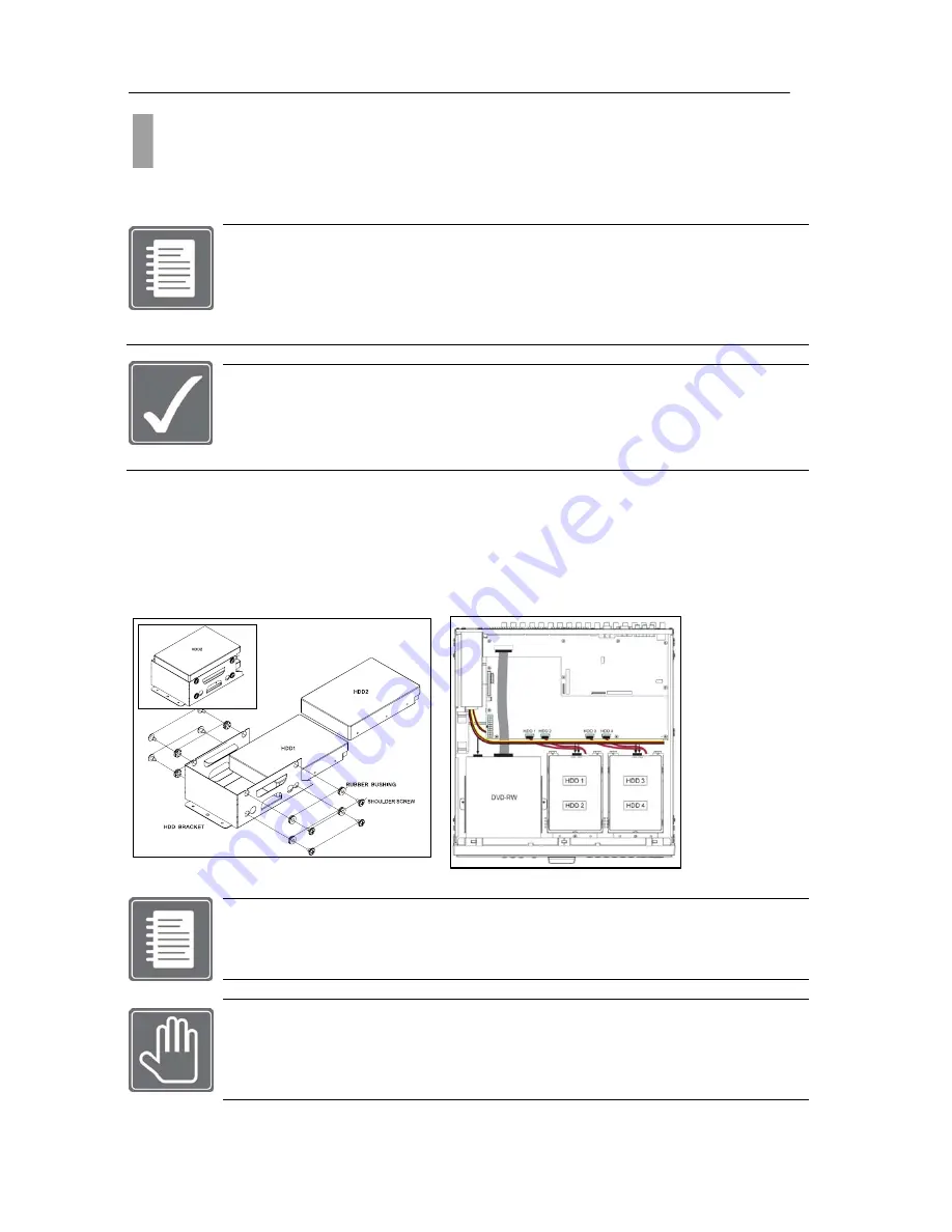
Up to four hard disk drives can be installed in the DVR.  You must disassemble the top cover of the DVR 
to expose the unit as seen below diagram.  The DVR uses Serial ATA hard disk drives.  

Only the approved hard disk drives will work in the DVR unit. You may obtain the 
compatibility list from your dealer.  Your dealer might perform the necessary upgrade for 
you. Consult your dealer for more details.  Improper handling or installation could void the 
warranty of both the hard disk drive and the DVR.  It is also strongly recommended to use 
same speed hard disk drive, and if possible match the model numbers of the hard disk 

drive to identical drives.  


CAUTION! Electrostatic discharges (ESD) 

Any


electrostatic


charge


in


contact


with


hard


disk


drives


or


other


electronic


components


in


the


DVR


unit


can


damage


them


permanently.


Improper


handling


could


void


the


warranty


of


the


hard


disk.


When


working


with


electrostatic


sensitive


devices


such


as


a


hard


disk


drive


or


the


DVR


unit,


make


sure


you


perform


installation


from


static


free


workstation.


Mounting Instructions 

Removing Top Cover 
With proper removal of the top cover there will be main board of the DVR and SATA connectors that are 
available.  

Locate


the


hard


drive


mounting


bracket


and


install


as


shown


below


example


in


Figure 4 Hard Disk Drive 

Mounting Bracket.


Figure 4 Hard Disk Drive Mounting Bracket 

 
For the single Hard Disk Drive installation please locate the marked SATA 1 or Primary 
SATA cables and connector and install the HDD to it.  


Upon completion of your hard disk drive installation, please perform following procedures.  
It is critical that you follow this procedure after hard disk installation to properly record 
video images to hard disk drives.  
1. Perform the Hard Disk Clear procedure  2. Check to see if proper size is allocated  
3. Perform factory reset procedure 


CHAPTER 3. HARDWARE CONFIGURATION 

2.  Hard Disk Drive and Optical Disk Drive Mounting 

Summary of Contents for H.264 Digital Video Recorder

Page 1: ......

Page 2: ...ERNET CONNECTION 18 11 EXTERNAL S ATA 19 12 USB CONNECTIONS 19 13 POWER CONNECTION 19 CHAPTER 4 FRONT PANEL KEY CONTROLS 20 1 KEYS 20 2 INDICATORS 21 3 MOUSE CONTROL 21 4 REMOTE CONTROL 21 CHAPTER 5 G...

Page 3: ...AL TIME 41 5 SWITCHING BETWEEN DISPLAY MODES 41 6 CHANNEL LED INDICATOR 42 CHAPTER 12 CAMERA 42 1 CAMERA SETUP 42 2 CAMERA COLOR ADJUSTMENT 43 3 PTZ CAMERA CONFIGURATION 44 4 PTZ OPERATION 46 5 MOTION...

Page 4: ...d for the wellness of the equipment and for the safety of the operator Please review and observe all instructions and warnings in this manual Note Keep this manual handy every time you operate this eq...

Page 5: ...t be connected with UL CUL or CSA approved power surge protector Avoid direct sun light and avoid heat RISK OF EXPLOSION IF BATTERY IS REPLACED BY AN INCORRECT TYPE DISPOSE OF USED BATTERIES ACCORDING...

Page 6: ...hat support BNC input or you may use a BNC to Composite Video adapter MON B can be used as an alternate display device Digital Spot out 3 Connect a display monitor that supports BNC input or you may u...

Page 7: ...s act as the output for the systems 2 Way Audio Communication feature External Device s Connection COM Data Power Sensor Relay 12 Connect a Data Network Cable RJ 45 type to this input ETHERNET Both yo...

Page 8: ...to lock the frontal keypad BOOK MARK This button is used during play back to bookmark a section of video Please refer to the section Book Mark for more details SMART BACK UP This button is used to qui...

Page 9: ...NEL SELECTION This button is used to select a specific channel 11 USB Port There are two 2 USB ports on the front side key panel of the DVR It is recommended to use the top port for Firmware Updates a...

Page 10: ...MENU button to enter and exit menu or a window Main Menu Icons Six main menu icons are SYSTEM DISPLAY CAMERA RECORD DEVICE and NETWORK You must first perform Date and Time Setup HDD Clear Factory Defa...

Page 11: ...the Start button and observe the IP address and other setting auto populated in to fields Static IP Example Choose the Static IP Radial button Populate the field provided below with IP address Subnet...

Page 12: ...mounting You will need to have Phillips screw driver and area safe from Electro Static Discharge ESD You will be required to remove smaller size screws to open and close the case Please be careful no...

Page 13: ...void the warranty of the hard disk When working with electrostatic sensitive devices such as a hard disk drive or the DVR unit make sure you perform installation from static free workstation Mounting...

Page 14: ...nection used as alternative video output for the purpose of public display guard monitor monitoring stations and other location where configuration or playback may not be needed Because of these natur...

Page 15: ...nel view in sequencing mode Sequencing interval may be defined to regulate the channel switching time Figure 7 1 Check this before connecting monitor There is BNC connector that is not being used It i...

Page 16: ...ification 1 Vpp 75 ohm PAL NTSC Auto Detect BNC Inputs With Loop Out The audio connections of DVR are used for both recording and monitoring purposes You have the option to disable both audio recordin...

Page 17: ...be controlled switched by a device such as a motion IR sensor door contact sensor and similar devices Each device can either be wired as N O or N C Normally Open Normally Closed This can be configure...

Page 18: ...through and make sure both ends of the cable are securely connected to the proper ports Consult your local IT administrator for detailed configuration procedures and setup The maximum cable length for...

Page 19: ...ort for the USB mouse connection Figure 15 USB Connector Port The power is supplied to the DVR by an internal power supply unit and can be either switched on or off by the toggle switch located on the...

Page 20: ...of the video Smart Back Up This button is used for quick AVI backup Open Used to eject and close the DVDRW or CDRW Drive Search Used to display the main search menu Rewind Used during playback to rew...

Page 21: ...e frontal keypad of the DVR may also be controlled via a USB mouse included To display and or access the main menu you can right click the mouse anywhere on the live view screen Once you right click t...

Page 22: ...shown on Monitoring popup menu Item 1 the selectable Sub Menu Item 2 items are Goto Channel Splitter PTZ Control Freeze Zoom Sequence PIP Audio Panic Playback Search and Setup Menu Example also shows...

Page 23: ...main menu press the Menu button on the frontal keypad or remote controller or you can right click the mouse from the live view display and click on Menu System Information User Authority Audio Buzzer...

Page 24: ...window by utilizing the drop down button located on the left hand corner for quick navigation Make sure that from the drop down list you select System Information Figure 21 System information with Ve...

Page 25: ...d disk drive is indicated in this window ITEM 1 Local HDD table Shows the detailed status information regarding locally installed hard disk drives ITEM 2 ODD table Shows the detailed status informatio...

Page 26: ...ately Failure to do so will damage the DVR and the hard disk drive Extension HDD table See Figure 23 Storage Tab Window of Item 2 Extension hard disk drive may be mounted on the DVR for alternative in...

Page 27: ...parameter to start deleting the recorded data regardless of storage space left over on the hard disk drive Example if parameter is 1 day even if there is enough hard disk storage space capable of rec...

Page 28: ...User setting and setting the authorities associated to each user types Also this section will indicate how to log in to the DVR unit and cover auto login procedures as well Administrator user Account...

Page 29: ...ser Account The Regular User Accounts are usually given to users that require performing certain task without having the full access of the privileges They are the simplest type of user account arrang...

Page 30: ...ing from Live display mode to Setup screen ITEM 6 Save and Cancel Save button use this button to commit the current configuration set on the HDD Clear window Cancel button use this button to cancel th...

Page 31: ...Figure 31 Buzzer Window After successful configuration of the audio in order for you to hear certain audio channel you must enable the audio from the Monitoring Popup menu Speaker device must be conn...

Page 32: ...ften desired that all DVR units to share certain configuration parameters Configuration files may be imported exported and applied with factory default operation applicable in six different categories...

Page 33: ...you perform Factory Default Configuration When the DVR unit has upgraded HDD Software Firmware update and when instructed by technical support agent to reconfigure the settings To navigate to the Fac...

Page 34: ...Tab selected To manually configure system time you must do so in Date Time window with Sys Time tab section See Figure 38 Date Time Window with Sys Time Tab selected In this window there are five conf...

Page 35: ...on DST Time tab button from Date Time window Figure 39 Date Time Window with DST Time selected Figure 39 Date Time Window with DST Time selected To enable DST option please locate On radial button and...

Page 36: ...n the Default button to reset all parameter in current window Save button use this button to commit the time configuration set on the Date Time window Cancel button use this button to cancel the time...

Page 37: ...e Shows date and time label for Live and Playback display Transparency setting has five different settings you could choose from They are Level 1 10 transparency Level 2 30 transparency Level 3 50 tra...

Page 38: ...tion to be connected to the DVR unit Check this first Your monitor must support below resolution Resolution rate of 640X480 at 60HZ or 70HZ refresh rate Resolution rate of 800X600 at 60HZ or 70HZ refr...

Page 39: ...the event in Channel 1 will complete and will move to next channel with an event Monitor Event Configuration Analog Spot Monitor configuration has full screen view switching between given interval ti...

Page 40: ...or there could be 21 different sequencing combinations To help you understand the configuration of digital spot option we will consider a scenario and configure the Digital Spot to meet the requiremen...

Page 41: ...Time Out radial button is On then you have selected the option to have setup menu return to live view after time selected on Setup interval time button will set all settings to default parameters Use...

Page 42: ...hat status you want to check from the LED of channel button CAMERA In this chapter all about the camera configuration and operation will be covered There are fixed camera and PTZ camera that the DVR u...

Page 43: ...olors Consult your monitor manual for details in color configuration Without having the color scheme correctly setup on the manual you may incorrectly adjust the color settings for the camera Figure 5...

Page 44: ...t among PTZs Step 3 Make sure that you PTZ device ID starts from 0 or 1 Some PTZs first configurable ID is from 0 If your PTZ starts from ID 0 then set the dipswitch setting to set to have ID 1 or oth...

Page 45: ...hey are last bit being used by your PTZ ITEM 7 Parity It is check sum bit parameter counted in either 0 or 1 ITEM 8 PTZ Speed ITEM 9 Copy Setting Upon selecting the Copy Setting button the Copy Settin...

Page 46: ...58 PTZ Control Panel Bar WIDE Used to Zoom In TELE Used to Zoom Out NEAR Focus In FAR Focus out OPEN Open Lens IRIS CLOSE Close Lens IRIS EXIT Exit PTZ Control Panel JOY STICK Move camera for pan and...

Page 47: ...etermine what is classified as motion You may specify the sensitivity levels and areas on each camera channel for motion events to be captured Figure 60 ITEM 1 Time Setting Under the Time Setting tab...

Page 48: ...63 on the next page ITEM 5 Dwell Time Is used to specify the post recording duration in seconds 1 99 Seconds after motion is captured To access the other menu options please click on each correspondi...

Page 49: ...will deactivate the select area Figure 64 Once you have finished setting up the motion mask zone press the right click button on your mouse and select Ok from the pop up menu to apply the changes you...

Page 50: ...o specify the post recording duration in seconds 1 99 Seconds after motion is captured To access the other menu options please click on each corresponding menu tab e g Day Setting Night Setting and Ac...

Page 51: ...Alarm Out Select this option to open the Alarm Out pop up menu to choose which sensor or relay will be activated when motion is detected Please refer to figure 68 Figure 69 Alarm Out To access the ot...

Page 52: ...e four profiles for configuring the record setup Normal This profile is used for standard scheduled recording The settings will be used under normal recording environments Event This profile is used f...

Page 53: ...in seconds the DVR will record prior to the alarm recording ITEM 2 Frame Rate NTSC 1 2 5 10 15 30 PAL 1 2 4 8 12 25 The DVR supports from 1 to 30 frames per second per channel The frame rate setting i...

Page 54: ...l button will discard all changes made and close the current window ITEM 7 Save The save button will apply all changes made to this configuration menu ITEM 8 Default The default button will restore al...

Page 55: ...ype The TYPE option is used to specify which pre alarm trigger to use e g MOTION OR ALARM Figure 75 Panic Tab Selected Panic This profile is used to specify the recording type when the Panic record bu...

Page 56: ...hese settings and will close the window ITEM 7 Save The save button will apply the changes made to this configuration menu ITEM 8 Check the desired entry s then press to remove it If you wish to add a...

Page 57: ...s to the recording schedule due to holiday hours and days of operation during these times Figure 79 Once you click on a specified date a pop up menu will appear refer to figure 80 Figure 80 To verify...

Page 58: ...n the top left side of the screen The search and playback menus are used to review the recorded video data on the DVR There are multiple search options you may use to find the desired video you wish t...

Page 59: ...he hour selection menu Figure 83 6 1 Select Time The select time will display the date and time specified by the user 6 2 Hour Display The hour display will show the available recorded video data on t...

Page 60: ...deo Loss Event Search allows a faster search method if the user prefers to view only Event recordings Panic Panic recording is a type of recording engaged by pressing the Panic button on the frontal k...

Page 61: ...sed to select the end time for the DVR to search for the specified events You can specify both date and time ITEM 5 Cancel The cancel button is used to close the current search window ITEM 6 Search Th...

Page 62: ...ts to be displayed for playback Figure 87 ITEM 1 Channel By pressing the drop down menu you are able to select the desired channel to begin the motion search option ITEM 2 Motion Start The motion star...

Page 63: ...ain Motion Search page Click on the search button to begin the motion search Motion Mask by Frontal Keypad To draw a motion mask in the desired zone use the directional keypad on the frontal keypad of...

Page 64: ...ion right click the live view screen with your mouse and choose search than book mark From the front keypad press search than choose book mark The following window will be displayed Figure 90 ITEM 1 L...

Page 65: ...ate and time End Time The most current available recorded video data on the hard drive indicated by the date and time HDD Status The location of the hard drive e g S ATA MASTER 1 2 3 OR 4 This section...

Page 66: ...the disc information of the blank media loaded in the CD DVD RW drive The size available for back up will be noted in this section If the media fails to load this section will state Initializing Medi...

Page 67: ...on the front panel of the DVR Once inserted navigate to the USB back up menu Figure 94 ITEM 1 Storage The storage section of this menu will display the USB media information The size available for bac...

Page 68: ...rwriting mode back up can be done from the data of more then 1 hour later of Recorded start time Because when the overwriting is on working the Recorded start time is changing continuously The RS 232C...

Page 69: ...The control ID is used to specify which ID type indicated by a number will be used for the external controller This is similar to the settings of a PTZ ID ITEM 3 Baud Rate The baud rate setting is us...

Page 70: ...emote Control 5 Remote Control 6 Each remote controller can operate up to 6 physical DVRs You use the ID settings to delegate which remote controller type will be used for which DVR since there will b...

Page 71: ...if you have chosen Static IP ITEM 5 Standard DNS Server You can only specify the Standard DNS Gateway if you have chosen Static IP ITEM 6 MTU Enable This setting is recommended when using PPPoE or PP...

Page 72: ...lue ITEM 2 DDNS Server NVRDDNS com is the host name of our DDNS server ITEM 3 Host Name The Host Name is your DVR ID This ID must be unique You can access your DVR via your web browser by entering You...

Page 73: ...ase click the NTP Server tab to access the menu Figure 102 ITEM 1 NTP Server You can choose to turn the NTP Server Function On or Off ITEM 2 Port You may specify the port number for the NTP Server or...

Page 74: ...on to specify how often in seconds 1 60 your DVR will try to connect with your Internet Service Provider You will see one of the following messages when trying to connect to your Internet Service Prov...

Page 75: ...inal factory settings please click on the Default button You may navigate to any other desired menu by click on the button located on the top left side of the screen Email Figure 105 ITEM 1 Send Email...

Page 76: ...a server to send event notifications to ITEM 1 IP Address Please specify an IP address of the PC that has the installed Event Server Program ITEM 2 Mode Please specify the type of event to send e g A...

Page 77: ...USER S MANUAL 77 P a g e...

Reviews: