background image

61

AQUAMAP™ 10x2/12x2 SERIES

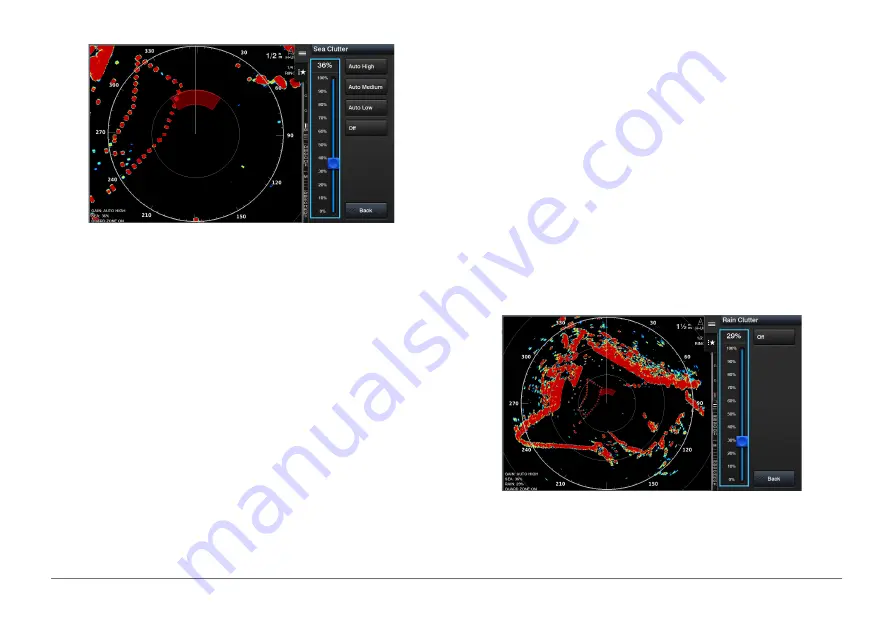
Clutter caused by choppy sea conditions.

NOTE: 

Not all options and settings are available on all radar and AQUAMAP 

models.

From a radar screen or the radar overlay, select 

MENU 

Sea Clutter

.

Select 

Presets 

or 

Auto

.

Select a setting that reflects the present sea conditions.

When using a compatible radar model, the AQUAMAP adjusts the sea clutter 

based on the sea conditions automatically.

Adjusting Sea Clutter on the Radar Screen Manually 

You can adjust the appearance of clutter caused by choppy sea conditions. 

The sea clutter setting affects the appearance of nearby clutter and targets 

more than it affects the appearance of distant clutter and targets. A higher sea 

clutter setting reduces the appearance of clutter caused by nearby waves, but 

it can also reduce or eliminate the appearance of nearby targets.

From a radar screen or the radar overlay, select 

MENU 

Sea Clutter

.

Turn the knob


to adjust the appearance of sea clutter until other targets 

are clearly visible on the radar screen.


Clutter caused by sea conditions may still be visible.

Adjusting Rain Clutter on the Radar Screen

The radar antenna’s vertical beamwidth is designed to see the water 

surface’s targets even during the vessel is rolling. By this design the radar 

also will detect the rain clutter such as rain, snow and hail etc in the same 

manner as the normal targets.
You can adjust the appearance of Rain Clutter caused by rain. Reducing the 

radar range also can minimize rain clutter.
The rain clutter setting affects the appearance of nearby rain clutter and 

targets more than it affects the appearance of distant rain clutter and targets. 

A higher rain clutter setting reduces the appearance of clutter caused by 

nearby rain, but it can also reduce or eliminate the appearance of nearby 

targets.

From a radar screen, select 

MENU 

Radar Options 

Rain Clutter

.

Turn the knob


to decrease or increase the appearance of nearby rain 

clutter until other targets are clearly visible on the radar screen.


Clutter caused by rain may still be visible.

Reducing Cross Talk Clutter on the Radar Screen 

You can reduce the appearance of clutter caused by interference from 

another nearby radar source, when the cross talk reject setting is on.

Summary of Contents for AQUAMAP 10x2 Series

Page 1: ...AQUAMAP 10x2 12x2 SERIES Owner s Manual...

Page 2: ...hadow Drive and SmartMode and are trademarks of Garmin Ltd or its subsidiaries These trademarks may not be used without the express permission of Garmin The Bluetooth word mark and logos are owned by...

Page 3: ...a Fields 6 Setting the Vessel Type 6 Adjusting the Backlight 7 Adjusting the Color Mode 7 Setting the Beeper 7 Charts and 3D Chart Views 7 Nav Chart and Offshore Fishing Chart 8 Selecting an Item on t...

Page 4: ...1 Moving a Saved Waypoint 21 Browsing for and Navigating to a Saved Waypoint 22 Deleting a Waypoint or an MOB 22 Deleting All Waypoints 22 Setting and Following a Direct Course Using Go To 22 Tracks 2...

Page 5: ...Hold 33 Tack and Gybe 33 Heading Line and Angle Markers 34 Setting the Heading and Course Over Ground Lines 34 Turning on Angle Markers 34 Sonar Fishfinder 35 Traditional Sonar View 35 Split Zoom Sona...

Page 6: ...LiveV and FrontV Sonar Settings 51 RealV Appearance Settings 52 LiveV and FrontV Appearance Settings 52 RealV Appearance Settings 52 Panoptix Transducer Installation Settings 52 Radar 54 Transmitting...

Page 7: ...or a Different Tide or Current Station 64 Viewing Almanac Information from the Nav chart 64 Sharing and Managing User Data 65 Copying Waypoints Routes and Tracks from HomePort to AQUAMAP 65 Selecting...

Page 8: ...for Music 75 Setting a Song to Repeat 75 Setting All Songs to Repeat 75 Setting Songs to Shuffle 75 Adjusting the Volume 75 Enabling and Disabling Zones 75 Muting the Media Volume 75 VHF Radio 75 Scan...

Page 9: ...work 85 Setting Up the Wi Fi Wireless Network 85 Connecting a Wireless Device to the AQUAMAP 85 Changing the Wireless Channel 85 Changing the Wi Fi Host 85 Wireless Remote Control 85 Pairing the Wirel...

Page 10: ...e with the AQUAMAP from the GRID Device 95 Rotating the GRID Joystick 95 Cleaning the Screen 95 Viewing Images on a Memory card 95 Screenshots 95 Capturing Screenshots 96 Copying Screenshots to a Comp...

Page 11: ...le sonar transmission HOME Press to return to the home screen MENU Press to open or close the options menu for each page FOCUS Press to move the highlight to a different section of a page Press to mov...

Page 12: ...ar screen press to show or hide the depth line On a radar screen press to open the VRM menu Protective Cover The protective cover protects the screen when the device is not in use To remove the cover...

Page 13: ...mputer 2 Go to Garmin com support software marine html TIP You can also download updated owner s manuals to load on the AQUAMAP from this web page 3 Select GPSMAP Series with SD Card 4 Select Download...

Page 14: ...ettings System GPS Source 2 Select the source for GPS data Customizing AQUAMAP Home Screen The home screen provides access to all of the features in the device The features are dependent on the access...

Page 15: ...elect Layout and select a new layout To customize the data shown on the screen select Overlays and select an option To resize the information areas shown on the screen use the arrow keys and press FOC...

Page 16: ...rom a compatible screen change the settings and view 2 Select MENU Save New 3 Enter a name and select Done Managing Presets You can customize the pre loaded presets and edit presets you created 1 From...

Page 17: ...Charts Nav Chart Shows navigation data available on your pre loaded maps and from supplemental maps if available The data includes buoys lights cables depth soundings marinas and tide stations in an o...

Page 18: ...ts Sea Conditions The Sea Conditions feature shows information about surface conditions including winds wave height wave period and wave direction Nav Chart and Offshore Fishing Chart NOTE The offshor...

Page 19: ...ent location select Measure Distance The distance and bearing appear on the screen Press SELECT to measure from a location other than your current location To view tide current celestial chart notes o...

Page 20: ...hing chart You must also enable animated icons in the chart settings An indicator for a tide station appears on the chart as a vertical bar graph with an arrow A red arrow pointing downward indicates...

Page 21: ...tracked If you discontinue vessel tracking the lost target symbol disappears from the chart or the 3D chart view Dangerous target in range The target flashes while an alarm sounds and a message banne...

Page 22: ...d heading and trails settings configured for one chart or one 3D chart view are applied to all charts and to all 3D chart views 1 From a chart or a 3D chart view select MENU Other Vessels Display Setu...

Page 23: ...n option To receive or ignore Emergency Position Indicating Radio Beacon EPRIB test signals select AIS EPIRB Test To receive or ignore Man Overboard MOB test signals select AIS MOB Test To receive or...

Page 24: ...hows high resolution satellite images on the land or on both land and sea portions of the Nav chart when certain premium maps are used Water Overlay Enables relief shading which shows the gradient of...

Page 25: ...ap zoomed in on the vessel s location in the corner of the main map Style Sets how the chart appears over 3D terrain Hazard Colors Shows shallow water and land with a color scale Blue indicates deep w...

Page 26: ...tours mapping feature allows you to instantly create maps with contours and depth labels for any body of water When Garmin Quickdraw Contours records data a colored circle surrounds the vessel icon Th...

Page 27: ...the Garmin Quickdraw Community using Garmin Connect website 1 Go to connect garmin com 2 Select Get Started Quickdraw Community Get Started 3 If you do not have a Garmin Connect account create one 4...

Page 28: ...the maps Garmin Quickdraw Contours Settings From a chart select MENU Quickdraw Contours Settings Display Displays Garmin Quickdraw Contours The User Contours option shows your own Garmin Quickdraw Co...

Page 29: ...direct course and a corrected course may pass over land or shallow water Use visual sightings and steer to avoid land shallow water and other dangerous objects NOTE Some chart views are available with...

Page 30: ...3 If necessary select Done The 50 nearest destinations that contain your search criteria appear 4 Select the destination Selecting a Destination Using the Nav chart From the Nav chart select a destina...

Page 31: ...If necessary select OK to navigate to the man overboard location If you selected OK the AQUAMAP sets a direct course back to the location If you selected another type of SOS the call details are sent...

Page 32: ...calculate part of the Auto Guidance line This is due to the settings for minimum safe water depth and minimum safe obstacle height 6 Follow the magenta line steering to avoid land shallow water and o...

Page 33: ...Marks Wpts Tracks Active Tracks Active Track Options 2 Select an option To record the track based on a distance between points select Distance Change and enter the distance To record the track based o...

Page 34: ...east one track 1 From a chart or a 3D chart view select MENU Marks Wpts Tracks Saved Tracks 2 Select a track 3 Select Follow Track 4 Select an option To navigate the track from the starting point used...

Page 35: ...1 Select NAV INFO User Data Routes Auto Guidance 2 If necessary select Filter to see routes only or Auto Guidance paths only Editing a Saved Route You can change the name of a route or change the turn...

Page 36: ...s In the center of the magenta line is a thinner purple line that represents the corrected course from your present location to the destination The corrected course is dynamic and it moves with your b...

Page 37: ...t NAV INFO User Data Routes Auto Guidance 2 Select a path and select Review Edit Adjust Path TIP When navigating an Auto Guidance path select the path on the Nav chart and select Adjust Path 3 Select...

Page 38: ...appropriate distance from shore you can assess the placement of the Auto Guidance path using one or more familiar destinations that require navigation through a narrow waterway Adjusting the Distance...

Page 39: ...horeline Distance setting Boundaries Boundaries allow you to avoid or remain in designated areas in a body of water You can set an alarm to alert you when you enter or exit a boundary You can create b...

Page 40: ...e Garmin Marine Network NOTICE Before you synchronize the user data across the network you should backup your user data to prevent possible data loss You can share waypoints tracks and routes with all...

Page 41: ...l be when the timer expires based on your current boat speed When the end point is before the start line the line is white This indicates the boat must increase speed to reach the start line on time W...

Page 42: ...he measured wind angle from the wind sensor The Manual option calculates the laylines using manually entered windward and leeward angles Windward Ang Allows you to set a layline based on the windward...

Page 43: ...d based tack or gybe NOTE Before you can enable the wind hold type you must connect a NMEA 2000 or NMEA 0183 wind sensor to the autopilot Setting the Wind Hold Type For advanced autopilot configuratio...

Page 44: ...ve position from the heading or course over ground which are helpful for casting or finding reference points Setting the Heading and Course Over Ground Lines You can show the heading line and the cour...

Page 45: ...een For example if you are viewing the split frequency view you can separately adjust the gain for each frequency If you do not see an arrangement of sonar views to suit your needs you can create a cu...

Page 46: ...H I R P CHIRP sonar provides amazingly clear target separation and definition because it puts more energy onto the target than traditional sonars Instead of sending just one single frequency CHIRP so...

Page 47: ...sonar 260 455 800 kHz provides a much clearer picture like image of what lies under the water by producing a more detailed representation of objects structures and fish under your boat SideV Sonar Vi...

Page 48: ...t Measure Distance Panoptix Sonar Views NOTE Not all models support Panoptix transducers To receive Panoptix sonar you need a compatible AQUAMAP and a compatible transducer The Panoptix sonar views al...

Page 49: ...onal view of what is behind your boat as you are moving and shows the entire water column in 3D from the bottom to the top of the water This view is used for finding fish 1 Color legend 2 Boat 3 Range...

Page 50: ...2 Select MENU Edit Combo 3 Select a sonar view Selecting the Transducer Type Before you can select the transducer type you must know what kind of transducer you have This AQUAMAP is compatible with t...

Page 51: ...ta NOTE Not all transducers save historical sonar data 1 From a sonar view hold to scroll through the history 2 Select BACK to exit history Stopping the Transmission of Sonar Signals From a sonar scre...

Page 52: ...to see more information on the screen This also increases noise and can make it more difficult to recognize actual returns 1 From a sonar view press MENU 2 Select Gain or Brightness 3 Select an option...

Page 53: ...to change the frequency quickly using the presets as the water and your goals change Viewing two frequencies concurrently using the split frequency view allows you to see deeper with the lower frequen...

Page 54: ...hift Zoom mode the fishfinder CPU only processes the sonar signals received from the selected depth range You can set the zoom manually 1 From a sonar screen select MENU ZOOM Shift Zoom 2 Select or to...

Page 55: ...rate at which the sonar image moves across the screen A higher scroll speed shows more detail especially while moving or trolling A lower scroll speed displays sonar information on the screen longer S...

Page 56: ...gnetic waves radiated from electric equipment and wirings The electromagnetic waves are then absorbed by the transducer cable and appear as vertical lines on the screen See figure B below A Interferen...

Page 57: ...r Scheme Sets the color palette Color Gain Adjusts the intensity of colors shown on the screen You can select a higher color gain value to see targets higher in the water column A higher color gain va...

Page 58: ...above or below the specified temperature Contour Sets an alarm to sound when the transducer detects a suspended target within the specified depth from the surface of the water and from the bottom Fish...

Page 59: ...ringing but can also reduce the strength of the returns This option is available on the Traditional sonar view only Filter Width Defines the edges of the target A shorter filter more clearly defines t...

Page 60: ...y returns and noise If you want to see all return information you can increase the gain to see more information on the screen This also increases noise and can make it more difficult to recognize actu...

Page 61: ...he bottom can appear on the screen as long as it appears within the range you have set Manually reducing this option can reduce the effectiveness of the FrontV Alarm reducing your reaction time to low...

Page 62: ...ferentiate low intensity returns higher in the water column but this causes a loss in the differentiation of the returns at the bottom You can select a lower color gain value when targets are near the...

Page 63: ...nting toward the port side of the boat This applies to Panoptix transducers in the LiveV Down RealV 3D Down and RealV 3D Historical sonar views Calibrate Compass Calibrates the internal compass in the...

Page 64: ...verify the area around the radar is clear before beginning radar transmission 1 With the AQUAMAP off connect your radar as described in the radar installation instructions 2 Turn on the AQUAMAP If nec...

Page 65: ...mation you need to see on the Radar screen For example do you need information about nearby weather conditions or targets and traffic or are you more concerned about distant weather conditions Assess...

Page 66: ...e Adjust Guard Zone Circle 2 Select the location of the outer guard zone circle 3 Select the location of the inner guard zone circle to define the width of the guard zone Defining a Partial Guard Zone...

Page 67: ...ARPA you must have a heading sensor connected and an active GPS signal The heading sensor must provide the NMEA 2000 parameter group number PGN 127250 or the NMEA 0183 HDM or HDG output sentence 1 Fro...

Page 68: ...applied to all other radar modes 1 From a radar screen use the knob to adjust the VRM 2 Use the arrow keys to adjust the cursor 3 Select SELECT Drop VRM EBL to set the VRM and EML Measuring the Range...

Page 69: ...t be applied to other radar modes or to the radar overlay NOTE This feature is not available on xHD open array or HD HD radome models Turning on Echo Trails From a radar screen select MENU Radar Optio...

Page 70: ...ear on the Radar screen This image can obscure smaller targets located near it 1 From a radar screen or the radar overlay select MENU Gain 2 Select Down to lower the gain until the smaller targets are...

Page 71: ...screen Clutter caused by sea conditions may still be visible Adjusting Rain Clutter on the Radar Screen The radar antenna s vertical beamwidth is designed to see the water surface s targets even duri...

Page 72: ...transmitting radar signals at set intervals Radar Setup Menu From a radar screen select MENU Radar Setup Source Selects the radar source when more than one radar is connected to the network Chart Disp...

Page 73: ...a stationary target located within viewable range 2 Measure the target bearing on the radar 3 If the bearing deviation is more than 1 set the front of boat offset Setting the Front of Boat Offset Bef...

Page 74: ...et moonrise moonset moon phase and the approximate sky view location of the sun and moon The center of the screen represents the sky overhead and the outermost rings represent the horizon By default t...

Page 75: ...If necessary select the memory card to copy data to 4 Select an option To transfer data from the memory card to the AQUAMAP and combine it with existing user data select Merge from Card To transfer da...

Page 76: ...gital selective calling DSC distress and position information from the radio The AQUAMAP can track the positions of vessels sending position reports If you have a Garmin NMEA 2000 VHF radio connected...

Page 77: ...overboard point If you cancel the man overboard distress call on the radio the AQUAMAP screen prompting you to activate navigation to the man overboard location disappears Man Overboard and SOS Distre...

Page 78: ...els Individual Routine Calls When you connect the AQUAMAP to a Garmin VHF radio you can use the AQUAMAP interface to set up an individual routine call When setting up an individual routine call from y...

Page 79: ...2 Select NAV INFO Warning Manager Save to Card Clearing all of the Messages Select NAV INFO Warning Manager Clear Warning Manager Gauges and Graphs The gauges and graphs provide various information ab...

Page 80: ...ed Min To set the maximum value of the standard operating range select Rated Max To set the lower limit of the gauge lower than the rated minimum select Scale Min To set the upper limit of the gauge h...

Page 81: ...Select Settings Alarms Fuel Total Fuel Onboard On 2 Enter the remaining amount of fuel that triggers the alarm and select Done Setting the Fuel Capacity of the Vessel 1 Select Settings My Vessel Fuel...

Page 82: ...uge select MENU Compass Gauge Heading Source 2 Select GPS Hdg or Magnetic NOTE When moving at low speeds or when stationary the magnetic compass source is more accurate than the GPS source Customizing...

Page 83: ...more detail in the variation To set the graph scale to the default scale select Reset Scale Setting Weather Alarm You can set a weather alarm to warn you when there is an abrupt change in atmospheric...

Page 84: ...AQUAMAP Select A V Gauges Controls Media Buttons NOTE Not all devices have these icons Button Description Press to select a source such as a connected iPod or AM radio Press to skip to the previous tr...

Page 85: ...en select MENU Media Menu Audio Levels Enable Disable Zones 2 Select a zone Muting the Media Volume 1 From the media screen select 2 If necessary press SELECT VHF Radio Scanning VHF Channels Before yo...

Page 86: ...o save as a preset 2 Select Presets Add Current Channel Selecting a Preset 1 From an applicable media screen select Presets 2 Select a preset from the list 3 Select Tune to Channel Removing a Preset 1...

Page 87: ...ite DAB stations as presets for easy access You can save up to 15 DAB station presets Saving a DAB Station as a Preset 1 From the DAB media screen select the station to save as a preset 2 Select Brows...

Page 88: ...cting a PoE device directly to a Garmin Marine Network AQUAMAP damages the Garmin AQUAMAP and may damage the PoE device Before you can view and control video devices such as IP cameras encoders and th...

Page 89: ...deo Settings Some cameras provide additional setup options NOTE Not all options are available on all camera models and AQUAMAP models You may need to update the camera software to use this feature Fro...

Page 90: ...he screen in the desired direction Creating a Combination with Video Functions You can include up to four video functions in a custom combination screen If your device has multiple built in video conn...

Page 91: ...ted to a compatible Garmin autopilot system you can engage and control the autopilot from the AQUAMAP For information about compatible Garmin autopilot systems go to Garmin com Opening the Autopilot S...

Page 92: ...the Helm With the autopilot engaged manually steer the boat The autopilot activates Shadow Drive mode When you release the helm and manually maintain a specific heading for a few seconds the autopilot...

Page 93: ...onnect the devices using a wireless connection You can connect up to five VIRB action cameras to the AQUAMAP After you connect the VIRB action camera with the AQUAMAP a new option is added to A V Gaug...

Page 94: ...VIRB Action Camera Video Playback You can view VIRB action camera video and images using the AQUAMAP NOTE The VIRB playback on the AQUAMAP is shown in the same quality as the live view on the AQUAMAP...

Page 95: ...i technology and search for wireless networks 2 Select the name of your AQUAMAP wireless network 3 Enter the network password Changing the Wireless Channel You can change the wireless channel if you h...

Page 96: ...ted to the AQUAMAP and would like to connect to a different AQUAMAP open the Boat Data screen hold UP and select Pair new 3 On the AQUAMAP select Settings Communications Wireless Devices Garmin Wearab...

Page 97: ...he system software or to purchase additional map data information Select Settings System System Information Software Information Viewing the Event Log The event log shows a list of system events Selec...

Page 98: ...ring this value can improve autopilot accuracy Speed Sources Sets the source for the speed readings Auto Guidance Sets the measurements for the Preferred Depth Vertical Clearance and Shoreline Distanc...

Page 99: ...urns in the Auto Guidance line are too wide select Settings Preferences Navigation Auto Guidance Shoreline Distance Near 7 If you selected Near or Far in step 6 review the placement of the Auto Guidan...

Page 100: ...d NMEA 0183 data for most AIS receivers select NMEA High Speed To support the input or output of Garmin proprietary data for interfacing with Garmin software select Garmin 4 Repeat steps 2 3 to config...

Page 101: ...on Alarm On A message banner appears and an alarm sounds when a MARPA tagged object or an AIS activated vessel enters the safe zone area around your boat The object is also labeled as dangerous on the...

Page 102: ...rature sensor or a temperature capable transducer Calibrate Water Speed Calibrates the speed sensing transducer or sensor Fuel Capacity Sets the combined fuel capacity of all the fuel tanks on your ve...

Page 103: ...nsor connected to the AQUAMAP measures the water temperature as being colder than it actually is Enter this value in step 5 as a negative number if the sensor connected to the AQUAMAP measures the wat...

Page 104: ...e AQUAMAP 2 Wait a few moments The AQUAMAP creates a file named GarminDevice xml in the Garmin folder on the memory card 3 Remove the memory card 4 Insert the memory card into your computer 5 On your...

Page 105: ...ot of any screen shown on your AQUAMAP as a Digital Switching Your AQUAMAP can be used to monitor or control circuits when a compatible system is connected For example you can control the interior lig...

Page 106: ...roubleshoot the cause of the power issue Make sure the power source is generating power You can check this several ways For example you can check whether other devices powered by the source are functi...

Page 107: ...2x2 1280 x 800 pixels Max power usage at 12 Vdc 34 8 W Typical current draw at 12 Vdc 2 2 A Max current draw at 12 Vdc 2 9 A Frequencies Traditional 50 200 77 200 kHz Single Channel CHIRP 40 to 240 kH...

Page 108: ...gnetic variance 129283 Cross track error 129284 Navigation data 129285 Navigation route and waypoint info Receive 065030 Generator average basic AC quantities GAAC 126992 System time 127488 Engine par...

Page 109: ...alling information DSE Expanded digital selective calling HDG Heading deviation and variation HDM Heading magnetic MWD Wind direction and speed MDA Meteorological composite MWV Wind speed and angle VD...

Page 110: ...in source code form remains a valuable trade secret of Garmin and or its third party providers You agree not to decompile disassemble modify reverse assemble reverse engineer or reduce to human readab...

Page 111: ...101 AQUAMAP 10x2 12x2 SERIES...

Page 112: ...support Garmin com Printed in Taiwan October 2017 190 02217 00_0A...

Reviews: