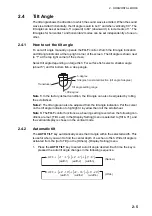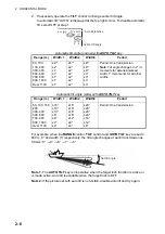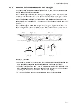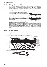
2. HORIZONTAL MODE
2-19
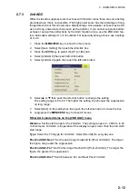
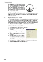
Setting between 4 and 7
: Echoes are quickly displayed and afterglow remains on the
screen longer as the setting is increased.
2.9.8
Reference bearing in frequency shift
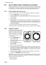
The reference bearing in frequency shift can be changed to avoid sonar interference
and noise. If noise or interference appears at a specific bearing, change the value of
the [Freq/Bearing Set] in the [TX/RX Setting] (H1 or H2 tab) - [Frequency] menu. The
setting range is 0°-358° and the default setting is 0°.
Note:
[Freq/Bearing Set] is valid when [Sidelobe Sup. A] (see subsection 2.9.9) is se-
lected to other than 0°).
2.9.9
How to suppress sidelobes
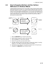
False echoes produced by sidelobes may appear on the display depending on the dis-
tribution pattern of a school of fish and the positional relationship between it and a ma-
rine object (reef, etc.) and wake reverberation. To reduce these sidelobes, use
[Sidelobe Suppress] in the [TX/RX Setting] menu (H1 or H2 tab).
Sidelobe suppression A
Watch the echoes while adjusting the suppression. The setting range is -3 to 4 (0 is
OFF). The larger the setting, the more the sidelobe is suppressed. For greatest sup-
pression, use a negative setting (-3 to -1).
Note:
When a negative value is used, [TX/RX Mode] in the [Display Setting] menu is
automatically selected to [Alternative]. See "Display Setting Menu" on page 7-3 for
details.
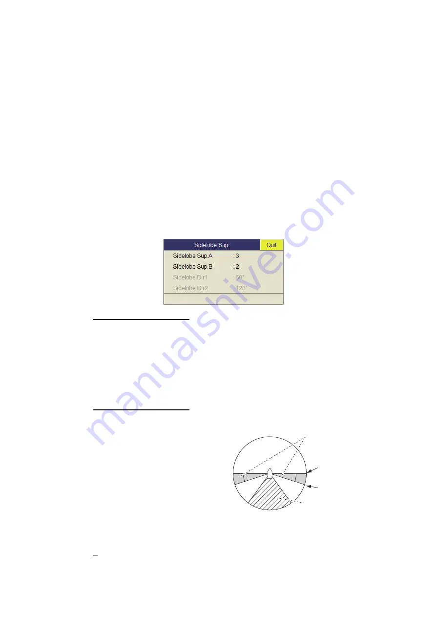
Sidelobe suppression B
For greater sidelobe suppression,
use [Sidelobe Sup. B]. The setting
range is 1 to 5. The larger the setting
value, the more the sidelobe is sup-
pressed; however, the width of the
beam increases thus resolution is
lower. The negative value setting (-5
to -1) is effective for reducing the ef-
fects of screw noise.
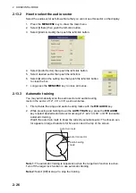
The area in which to suppress sidelo-
bes with [Sidelobe Sup. B] can be set
with [Sidelobe Dir1] and [Sidelobe Dir2]. The setting range is 0°
[Sidelobe Dir1]
[Sidelobe Dir2]
180°, symmetrical in port-starboard directions. An area can be set
when [Sidelobe Sup. B] is 0 - 5. In this case the settings of Dir1 and Dir2 are gray.
Sidelobe bearing 1
Sidelobe bearing 2
Area in which SIDELOBE
SUP. B works (port-star-
board symmetrical)
Echo from screw
noise
Summary of Contents for FSV85MK2
Page 12: ...SYSTEM CONFIGURATION xii This page is intentionally left blank ...
Page 74: ...2 HORIZONTAL MODE 2 44 This page is intentionally left blank ...
Page 128: ...4 SLANT MODE 4 36 This page is intentionally left blank ...
Page 132: ...5 NUMERIC GRAPHIC DATA DISPLAY 5 4 This page is intentionally left blank ...
Page 188: ...9 MAINTENANCE 9 24 This page is intentionally left blank ...
Page 199: ......

