2. HORIZONTAL MODE
2-8
2.4.4
Tilt angle for surface fish
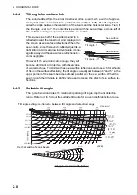
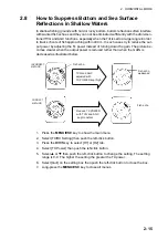
The sound emitted from the sonar transducer forms a beam with a width of approxi-
mately 10° in the vertical direction (vertical beam width at -6 dB). The tilt angle indi-
cates the angle between the centerline of the beam and the horizontal plane. Then, if
the tilt angle is set to 0°, the centerline is parallel with the sea surface and one half of
the emitted sound goes upward, toward the sea surface.
This causes one half of the emitted sound to be
reflected toward the transducer and displayed on
the screen as sea surface reflections. When the
sea is calm, since the sound is reflected just like a
light hitting a mirror at a low incident angle, it prop-
agates away and the sea surface reflections be-
come negligible.
However if the sea is not calm enough, they will
become dominant and interfere with observation
of wanted echoes. To minimize these sea surface reflections and to search for schools
of fish on the surface effectively, the tilt angle is usually set between 4° and 5° so the
upper portion of the beam becomes almost parallel with the sea surface. When the
sea is rough, the tilt angle is slightly increased to lessen the affect of sea surface re-
flections.
2.4.5
Suitable tilt angle
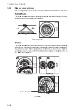
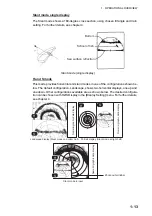
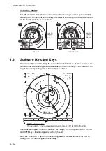
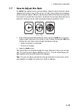
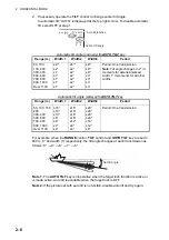
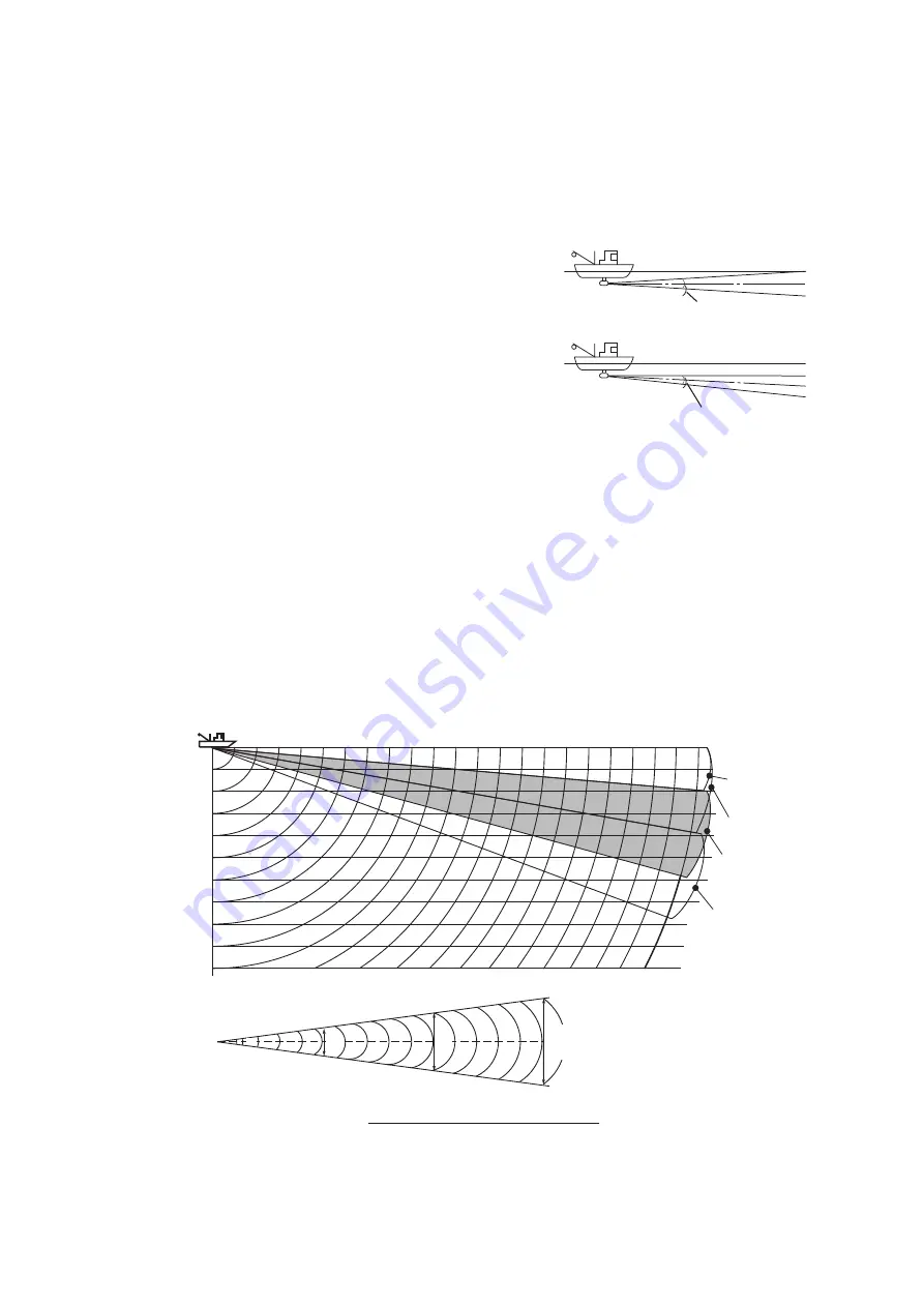
The figure below illustrates the relationship among tilt angle, depth and detection
range. Refer to it to find out the suitable tilt angle for a given depth/detection range.
Tilt angle 0
q
Sea surface
Tilt angle 4-5
q
Sea surface
10
q
10
q
Range(m)
Vertical width of sonar beam
Depth (m)
Tilt angle setting: relationship between tilt angle and detection range
(-6dB)
100
(200)
200
(400)
300
(600)
400
(800)
Tilt 0
°
(0°-5°)
20(40)
40(80)
60(120)
80(160)
100(200)
200(400)
10
q
17 m
100 m
100 m
300 m
52 m
200 m
35 m
Tilt 5
°
(0°-10°)
Tilt 15
°
(10°-20°)
Tilt 10
°
(5°-15°)
In grey
Tilt angle and beamwidth (80kHz)
Summary of Contents for FSV85MK2
Page 12: ...SYSTEM CONFIGURATION xii This page is intentionally left blank ...
Page 74: ...2 HORIZONTAL MODE 2 44 This page is intentionally left blank ...
Page 128: ...4 SLANT MODE 4 36 This page is intentionally left blank ...
Page 132: ...5 NUMERIC GRAPHIC DATA DISPLAY 5 4 This page is intentionally left blank ...
Page 188: ...9 MAINTENANCE 9 24 This page is intentionally left blank ...
Page 199: ......

