background image

10.  MAINTENANCE

10-7

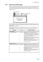
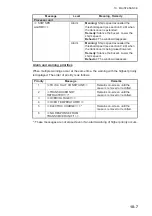
Alarm and warning priorities

When multiple warnings occur at the same time, the warning with the highest priority 
is displayed. The order of priority is as follows:

*: These messages are not erased even if an alarm/warning of higher priority occurs.

Processor unit

<< SHIP SPD 
ALARM!! >>

Alarm

Meaning:

 Ship’s speed exceeded the 

threshold speed (see section 9.2.9) when 
the transducer is extended.

Remedy:

 Silence the buzzer. Lower the 

ship’s speed.

Behavior:

 The window disappears.

Alarm

Meaning:

 Ship’s speed exceeded the 

threshold speed (see section 9.2.9) when 
the transducer is being raised/lowered.

Remedy:

 Silence the buzzer. Lower the 

ship’s speed.

Behavior:

 The window disappears.

Priority

Message

Remarks

1

<<TD IS A HALT CONDITION!!>>

Remains on-screen until the 
cause is removed or rectified.

2

<<TRANSDUCER NOT 
RETRACTED!! >>*

Remains on-screen until the 
cause is removed or rectified.

3

<<OVERVOLTAGE!! >>

4

<<OVER TEMPERATURE!! >>

5

<<ELECTRIC CHARGE!! >>*

Remains on-screen until the 
cause is removed or rectified.

6

<<NO RESPONSE FROM 
TRANSCEIVER UNIT!! >>

Message

Level

Meaning, Remedy

Summary of Contents for FSV-75

Page 1: ...OPERATOR S MANUAL www furuno com HALF CIRCLE COLOR SCANNING SONAR Model FSV 75 FSV 75 3D ...

Page 2: ...al is elemental chlorine free FURUNO Authorized Distributor Dealer 9 52 Ashihara cho Nishinomiya 662 8580 JAPAN A APR 2019 Printed in Japan All rights reserved D3 JUL 16 2020 Pub No OME 13630 D3 REFU FSV 75 0 0 0 1 9 5 8 6 7 1 3 ...

Page 3: ...marks and service marks belong to their respective holders How to discard this product Discard this product according to local regulations for the disposal of industrial waste For disposal in the USA see the homepage of the Electronics Industries Alliance http www eiae org for the correct method of disposal How to discard a used battery Some FURUNO products have a battery ies To see if your produc...

Page 4: ...lls into the equipment Do not operate the equipment with wet hands Electrical shock may result Use the proper fuse Use of a wrong fuse can result in damage to the equipment or cause fire Do not install the equipment where it may be subject to rain or water splash Fire or electrical shock can result if water leaks in the equipment Do not disassemble or modify the equipment Fire electrical shock or ...

Page 5: ...lt if not replaced allowing water leakage and or loss of transducer The LCD is made of glass Do not apply force or shock to the LCD Broken LCD glass can cause injury When checking the brake on the hull unit always take measures against static electricity Static electricity can cause the unit to move unexpectedly which can result in personal injury to damage to the unit Extended 18 kn 15 kn Raising...

Page 6: ...nnot be raised or lowered The transducer is also stopped when the ratchet wrench in the hull unit which is used to manually raise the transducer is re moved from its holder To release the emergency stop condition first confirm that no one is near the hull unit Then do the following To release the EMERGENCY STOP button turn the button in the direction of the arrow on the button Return the ratchet w...

Page 7: ... Slant Display Overview 2 2 2 3 Display Range 2 3 2 4 Tilt Angle 2 4 2 4 1 How to set the tilt angle 2 4 2 4 2 Automatic tilt 2 5 2 4 3 Relation between bottom echo and tilt angle 2 6 2 4 4 Tilt angle for surface fish 2 7 2 4 5 Suitable tilt angle 2 7 2 5 Sweep Angle 2 8 2 5 1 How to set the sweep angle 2 8 2 5 2 Auto sweep function 2 9 2 6 How to Measure Range and Bearing to a Target 2 10 2 7 How...

Page 8: ...ith the fish estimate mark 2 29 2 17 2 How to compare with the circle cursor 2 30 2 18 How to Measure the Speed of a School of Fish 2 31 2 18 1 How to measure the speed of a school of fish 2 31 2 18 2 How to delete fish marks 2 32 2 19 Event Mark Own Ship Position Mark 2 33 2 19 1 How to enter an event mark 2 33 2 19 2 How to enter an own ship position mark 2 34 2 19 3 How to erase an event mark o...

Page 9: ...lay Setting menu 3 17 3 12 2 Picture Setting menu 3 20 4 FISH FINDER MODE 4 1 4 1 Basic Operating Procedure 4 1 4 2 Fish Finder Display Overview 4 2 4 3 How to Select a Display Range 4 2 4 4 How to Adjust the Gain 4 3 4 5 How to Select Picture Advance Speed 4 3 4 6 How to Measure Depth Distance 4 4 4 7 How to Reject Interference 4 4 4 8 How to Erase Weak Echoes 4 5 4 9 How to Reject Low Level Nois...

Page 10: ... 22 5 13 2 How to show hide the fish mark 5 23 5 13 3 How to show hide the net course mark 5 24 5 13 4 How to set the range ring display 5 24 5 13 5 How to set the depth scale display 5 25 5 13 6 How to set the detection beam display 5 26 5 13 7 How to set the own ship mark display 5 27 5 13 8 How to set the plumb line display 5 28 5 14 Seabed Detection Setting 5 29 5 15 Setting Menus for the Came...

Page 11: ...enu description 9 1 9 2 Mark Operation Support Tool Menu 9 2 9 2 1 How to open the Mark Operation Support Tool menu 9 2 9 2 2 Erase Marks menu 9 2 9 2 3 Mark Display menu 9 3 9 2 4 Mark Color Size menu 9 5 9 2 5 Mark Data menu 9 6 9 2 6 Current VEC Wind menu 9 7 9 2 7 Net Course Mark menu 9 8 9 2 8 Net SONDE Setting menu 9 9 9 2 9 Alarm Audio menu 9 10 9 3 Installation Setting Menu 9 11 9 3 1 How ...

Page 12: ...ern 10 15 10 10 8NMEA monitor 10 16 10 11Hull Unit for Technicians Only 10 17 10 11 1Hull unit maintenance 10 17 10 11 2How to raise the transducer 10 21 10 11 3How to check the brake in the hull unit 10 23 APPENDIX 1 MENU TREE AP 1 APPENDIX 2 ERROR CODE LIST AP 8 APPENDIX 3 DATA INPUT REQUIREMENTS AP 12 APPENDIX 4 BRAKE TEST AP 13 SPECIFICATIONS SP 1 INDEX IN 1 ...

Page 13: ...ctions from the control panel 32 color display to help you determine density and variation in fish schools Auto target lock function to keep your targeted school in sight Store up to 10 sets of settings to quickly change your setup for varying tasks Save and replay echo images Multiple marks and indications to help you identify fish finder data and voyage data at a glance Robust diagnostics 3D fun...

Page 14: ... documentation and or other materials provided with the dis tribution 3 All advertising materials mentioning features or use of this software must display the following acknowledgment This product includes software developed by the OpenSSL Project for use in the OpenSSL Toolkit http www openssl org 4 The names OpenSSL Toolkit and OpenSSL Project must not be used to endorse or pro mote products der...

Page 15: ...arts of the library used This can be in the form of a textual message at program startup or in documentation online or textual provided with the package Redistribution and use in source and binary forms with or without modification are permitted pro vided that the following conditions are met 1 Redistributions of source code must retain the copyright notice this list of conditions and the followin...

Page 16: ...N ANY WAY OUT OF THE USE OF THIS SOFTWARE EVEN IF ADVISED OF THE POSSIBILITY OF SUCH DAMAGE The licence and distribution terms for any publically available version or derivative of this code cannot be changed i e this code cannot simply be copied and put under another distribution li cence including the GNU Public Licence ...

Page 17: ...V 7503 12 24V DC Hull Unit FSV 753 800 mm travel FSV 754 1100 mm travel Matching Box FSV 7550 100 110 115 220 230V AC 1Ø 50 60 Hz 200 220V AC 3Ø 50 60 Hz Transceiver Unit FSV 751 Control Box FSV 7530 Standard supply Option or local supply Switching HUB External KP Gyrocompass AD 100 NMEA0183 Equipment Max 5 USB3 0 Device Max 2 USB2 0 Device Max 2 Speaker SEM 21Q 100 110 115 220 230V AC 1Ø 50 60 Hz...

Page 18: ...the FCV 1900 B G con nection between the FSV 75 and the FCV 1900 B G is not available Name Type Model Remarks Display Unit MU 190 Brilliance control is available with direct USB connection to the FSV 7503 The USB cable for brilliance control should be connected directly to the FSV 7503 Do not use a USB hub MU 190HD Color Sounder Fish Finder FCV 1200L 1 FCV 1200LM FCV 1500L 1 Fish Finder FCV 1900 2...

Page 19: ...key is programmed to Fixed Position Lowers the transducer to half protrusion If the mid protrusion key is programmed to Any Position The transducer stops at desired position If the mid protrusion key is programmed to Fixed Position Raises the transducer If the mid protrusion key is programmed to Any Position The transducer stops at desired position 1 2 3 4 5 6 7 8 9 10 11 12 13 14 15 16 17 18 19 2...

Page 20: ...mark Resets the sweep angle to 0 Resets the tilt angle to 0 Select the display slant display or 3D display to be controlled The current operative display is highlighted with an orange frame Turns the Auto Sweep function on off Turns the Auto Tilt function on off If 1 Mode Selection section 9 3 3 is set to Mode Key Selects the display mode If 1 Mode Selection is set to Pull Down Menu Opens the pull...

Page 21: ...settings 3 Right button long press Return the own ship mark to the center of the screen Scrollwheel Spin Changes the value for settings Spin Selects a menu item Spin Adjusts tilt range gain and sweep Spin Changes the selected User Program Short press Confirms the selection shows the circle cursor changes the color reference echo strength based or depth based for the 3D display Long press Opens the...

Page 22: ...rom the switchboard or breaker Note If the breaker on the hull unit is turned on after the raise lower keys or on the control unit are pressed beware of the moving hull unit 2 The operation of holding down the left button while moving the trackball is referred to as drag drop in this manual 3 The following marks can be assigned to the left right buttons as a shortcut To change the de fault setting...

Page 23: ...r goes off by power failure etc use the key to retract the transducer and then operate the system Turning the power off 1 First retract the transducer with the key The lamp to the left of the key flash es while the transducer is being raised and lights steadily when it is fully raised Note While raising the transducer the ship speed must be not exceed 15 knots to prevent damage to the transducer a...

Page 24: ...d while the transducer is being raised or lowered the transducer stops at the fixed position The fixed position can be set by clicking the transducer position marker See the next page Any Position The transducer starts lowering when the key is operated The low ering is stopped when the key is operated To raise or lower the transducer from the current position use the or key The key does not contro...

Page 25: ... at the top left corner lets you check how far the transducer is protruding You can show or hide the marker by doing the following operation Main menu 0 Mark Operation Support Tool 2 Mark Dis play 0 Next 2 TD Position Mark The color of the indicator changes according to transducer position and operation state Green The transducer is fully retracted Brown yellow Transducer stopped at position other...

Page 26: ... 1 5 1 How to adjust the screen brilliance If your monitor is one of those listed as compatible on page xvi and the monitor is con nected to the control unit via USB you can adjust the screen brilliance from the control unit Turn the BRILL knob clockwise to increase or counter clockwise to decrease the brilliance Note If your monitor is not listed on page xvi brilliance cannot be adjusted from the...

Page 27: ...ing menu appears 4 Select 2 Operation Setting then left click 5 Select 7 Dimmer then left click 6 Left click the S or T button to change the setting 7 Left click Quit to complete the setup and close the pop up 8 Press and hold the MENU ESC key until the menu closes The process of closing the menu is abbreviated to Close the menu in the rest of this manual ...

Page 28: ... select a display mode do the following procedure If 1 Mode Selection see section 9 3 3 is set to Mode Key Press the DISP MODE key several times until the desired display appears If 1 Mode Selection is set to Pull Down Menu Press the DISP MODE key to open the pull down menu Left click an appropriate display mode from the pull down menu You can select the display modes that are registered to 1 Regi...

Page 29: ...n the main menu 2 Select 5 Record Recall Register then left click You can also open the Record Recall Register menu from the right click pop up menu See Operation from the right click pop up menu on page 1 16 3 Select 7 Register then left click 4 Left click 1 Register Display Mode 5 Select desired modes you may select as many modes as you wish then left click Quit 6 Close the menu Mode programmed ...

Page 30: ...ep angle is fixed to 0 and the tilt angle is fixed to 90 The echoes are vertically inverted on the slant display For further details see chapter 3 Fish finder display overview The FSV 75 can show the picture from the fish finder in combination with the sonar echoes For further details see chapter 4 Note Requires connection of a fish finder Bottom School of fish Sea surface reflection Sweep angle 0...

Page 31: ...s to frequently used functions You can see the current setting for each software function key With all menus closed place the cursor at the bottom of the screen for approx two seconds to show the settings Shortcuts are display in numerical order 1 F1 key s function appears at the left end and 0 F10 key s function appears at the right end Left click a function to get the corresponding action See se...

Page 32: ...ere between positions 3 and 7 Turn the GAIN knob to adjust the setting Turn the control clockwise to increase the gain counterclockwise to decrease the gain New gain setting is momentarily displayed in large characters at the top of each display The setting value is always displayed next to G at the top right corner of the screen Note The gain can also be adjusted from the gain indication Select t...

Page 33: ...reviated to Select in this manual Note You can select the menu item by pressing the corresponding numeric key function key For example press the 0 F10 key to open the Mark Operation Support Tool menu 3 Press the left button the process of pressing the left button is abbreviated to left click in this manual If you selected an item using the scrollwheel push the scrollwheel For example if you select...

Page 34: ...menu items are displayed in red text The contents of these menus are protected against unintentional or accidental change When a locked menu is selected a confirmation message appears For example the following confirmation message appears when you select 2 Assign User Program located at main menu 5 Record Recall Register 7 Register Select the appropriate option then left click If you prefer not to...

Page 35: ...nsducer If the mid protrusion key is programmed to Fixed Position Lowers the transducer to half protrusion If the mid protrusion key is programmed to Any Position The transducer stops at desired position If the mid protrusion key is programmed to Fixed Position Lowers the transducer to full protrusion If the mid protrusion key is programmed to Any Position The transducer stops at desired position ...

Page 36: ...㻾㻻 㻡㻜㻿 S Trackball data Slant range Horizontal range Depth Relative bearing or True bearing Event mark data Horizontal range Present depth Depth at measured Relative bearing or True bearing Latest event mark 1 Cursor Target lock mark 1 Event mark 1 Bearing scale 1 Range ring Own ship mark 1 Heading mark 1 Target lock fish movement data Horizontal range Depth Speed Course 1 Latest fish mark 1 Fish ...

Page 37: ...s at the top of the screen Range is always displayed next to R at the top right hand corner of the screen Note 1 The range can also be adjusted from the range indication Put the cursor on the range indication to highlight it in yellow then spin the scrollwheel Note 2 In the target lock function the range is automatically changed according to target position if Tilt Interlock Target Lock menu is se...

Page 38: ...dis played next to T at the top right hand corner of the screen Select the tilt angle depending on target fish For surface fish select a shallow angle about 5 and for bottom fish a deep angle Note 1 The default function of the scrollwheel sets the tilt angle Note 2 The tilt angle can also be adjusted from the tilt angle indication Put the cursor on the tilt angle indication to highlight it in blue...

Page 39: ...he top right hand corner of the screen next to the tilt angle The current auto tilt angle also appears in parentheses below the tilt indication 2 If necessary operate the TILT control to change the center of the tilt range 3 To disable auto tilt press the AUTO TILT key again Automatic tilt angles with AUTO TILT key For example when the RANGE TILT and 1 Auto Tilt Range key are set to 800 m 30 and 4...

Page 40: ...ted above the bottom Case 3 Tilt angle 0 to 5 This tilt angle may or may not capture the bottom since the returning bottom echo is weak The school of fish is located close to the bottom Points to consider Normally a vertically distributed school of fish is a better sonar target than the bot tom because it reflects the transmitted pulse back toward the transducer In case 3 both schools of fish a an...

Page 41: ...sea is not calm enough they will become dominant and interfere with observation of wanted echoes To minimize these sea surface reflections and to search for schools of fish on the surface effectively the tilt angle is usually set between 4 and 5 so the upper portion of the beam becomes almost parallel with the sea sur face When the sea is rough the tilt angle is slightly increased to lessen the af...

Page 42: ...ed in 1 intervals factory default 2 However the SWEEP control is held for more than three seconds the interval changes based on the setting selected at 4 Sweep Angle Interval located at main menu 9 Installation Setting 2 Operation Setting 6 Sweep Tilt Settings 1 The start and end angle of the available range is dependent on offsets set at instal lation See the Installation Manual for details 2 You...

Page 43: ... the auto sweep marker indicating the center of the sweep range The marker also moves accordingly when the center of the range is changed 2 Push the SWEEP control to move the center of the sweep area as required 3 Press the AUTO SWEEP button again to deactivate the function Note 1 If target lock is activated while auto sweep is active auto sweep is automati cally deactivated In this case auto swee...

Page 44: ...nge mark and bearing mark appear intersecting the location selected at step 1 Further the range and bearing to the target appear at the bottom of the screen Note 1 You can clear the range and bearing marks and the indications at the bottom of the screen Place the cursor on or near the own ship symbol then press the R B AUDIO key Note 2 If 5 Audio located at main menu 0 Mark Operation Support Tool ...

Page 45: ...on loss of sound in water amplification of echoes on short range is suppressed and gradually increased as range increases so that similar targets are displayed in the similar intensities irrespec tive of the ranges to them 2 7 1 How to set the TVG curve You can adjust the gain change for the TVG curve do as follows 1 Open the menu 2 Select 2 Gain Setting then left click 3 Select 1 TVG Curve then l...

Page 46: ...r Gain Distance 7 Left click the S or T button to select the desired setting The available setting range is 0 0 to 10 0 The higher the setting value the high er the gain however at setting 5 0 no gain adjustment is applied 8 Select Quit then left click 9 Close the menu Note With factory default settings you can use the shortcut keys 8 F8 Near Gain or 9 F9 Far Gain to switch between the gain settin...

Page 47: ...ee section 2 8 2 1 Open the menu 2 Select 2 Gain Setting then left click 3 Select 8 AGC Distance then left click 4 Left click the S or T button to select the desired setting The available setting range is 20 m to 2000 m in 20 m steps 5 Select Quit then left click 6 Select 6 Near AGC or 7 Far AGC as required then left click 6 AGC Near Suppress gain in area closer than the 3 Near Gain Distance 7 AGC...

Page 48: ...the wa ter While a longer pulse is advantageous for long range sounding it has the disad vantage of being poor in discrimination of targets that is the ability to separate several closely located targets When searching for bottom fish therefore it is useful to short en the pulse length in order to separate fish echoes from bottom reflections Decrease the pulse length setting to shorten the pulse l...

Page 49: ...eak echoes only leaving echoes schools of fish unadjusted 1 Open the menu 2 Select 2 Gain Setting then left click 3 Select 9 Noise Suppression then left click 4 Left click the S or T button to select the desired setting The available setting range is 0 0 to 10 0 The higher the setting value the high er the reduction Adjust this setting with caution so as not to hide smaller schools of fish 5 Selec...

Page 50: ...ower by adjusting the Tx output instead of turning down the gain The picture becomes clearer when output power is reduced rather than when the GAIN is decreased as illustrated below How to reduce the TX power 1 Open the menu 2 Select 1 TX RX Setting then left click 3 Select 3 Transmission Power then left click 4 Left click the S or T button to select the desired setting The setting range is 0 to 9...

Page 51: ...arious speeds to check if the noise is speed dependent If neither of the above two steps has effect on the picture adjust one of the following 2 10 2 Change the TX interval When other sonars nearby are operating the same transmission interval as that of own ship s sonar rings of interference appears on the display To remove the rings from the screen do the following 1 Open the menu 2 Select 1 TX R...

Page 52: ...uipment 4 Left click the S or T button to select the desired setting 2 Interference Reject 7 Auto Sweep INT REJ the setting range is 0 to 3 The degree of rejection in ascending strength is 2 1 3 0 disables the in terference rejector 3 INT Reject FF the setting range is 0 to 6 A higher setting increases the amount of interference rejected 0 disables the interference rejector 5 Select Quit then left...

Page 53: ...ing Wide Retains a wide bandwidth Noise is reduced slightly Middle Adjust the bandwidth to mid range This is the most commonly used setting with average noise reduction Narrow Narrows the beam Noise reduction is large Note Selecting Narrow may cause fast moving fish such as tuna to be lost due to noise gain adjustments 5 Select Quit then left click 6 Close the menu 2 10 6 Noise limiter Weak unwant...

Page 54: ... screen longer as the setting is increased Settings between 8 and 11 Echoes are quickly displayed and afterglow remains on the screen longer as the setting is increased Adjust 1 Echo Average for regular use adjust 6 Auto Sweep Echo AVG for echo averaging while the auto sweep function is active The setting for both items should be the same 2 10 9 2nd echo rejection A target that is farther than the...

Page 55: ...put For details see DATA INPUT REQUIREMENTS on page AP 12 Only one target lock can be active at any time Note The target lock function is unavailable when the display mode is 3D 3D S or 3D FF 2 12 1 How to select the target lock mode Note Target lock mode cannot be changed if a target lock is active 1 Open the menu 2 Select 0 Mark Operation Support Tool then left click 3 Select 8 Target Lock then ...

Page 56: ...k changes to red color and the tracking mode changes to position mode see next section at that position When the so nar detects and tracks the target again the Fish mode is restored 4 To disable the target lock press the TARGET LOCK key 2 12 3 Target mark mode This mode tracks a stationary position such as a reef using position data fed from a navigator 1 Select Target Mark in the procedure in sec...

Page 57: ...cks a target whose signal level is greater than set here 2 Bottom Threshold When a target is judged as a bottom echo raise this set ting to differentiate bottom from target The setting range is 0 to 5 3 Target Speed Limit Sets maximum fish speed to track The setting range is 1kn to 15kn 4 Smoothing Sets smoothing rate for fish speed data The higher the figure the smoother the position of the targe...

Page 58: ...osi tion is fixed at the screen center and own ship mark pivots with ship s movement Echoes from fish and the bottom move on the screen relative to own ship s movement Course up The display is oriented according to course Own ship position is fixed at the screen center Echoes from fish and the bottom move on the screen relative to own ship s movement Targets are displayed at ship s bow 2 13 2 How ...

Page 59: ...g fish increases in volume For departing fish the volume decreases 6 Select Quit then left click 7 Close the menu When audio is active With the appropriate data input see DATA INPUT REQUIREMENTS on page AP 12 and the audio feature is active the audio bearing marker appears on the screen If the setting for 7 Audio Sector see section 2 14 2 is set to other than OFF the auto sweep is automatically ac...

Page 60: ...earing 1 Place the cursor on the direction you want to monitor through the speaker 2 Press the R B AUDIO key The audio bearing mark appears on the bearing selected and the center of the au dio sector is located at the selected bearing Note To erase the range mark and the data at the bottom of the screen put the cursor near own ship mark and press the R B AUDIO key Note that the audio bearing is al...

Page 61: ... shaped alarm zone The alarm range appears on the display as shown below 10 Push the left click button 11 Close the menu When a fish echo enters the alarm area the buzzer sounds Note 1 There must be at least three degrees difference between the starting and end ing points to get a fan shaped alarm zone as shown in a and b below Otherwise the unit paints a 360 degree alarm zone as in c where there ...

Page 62: ...k 6 Select Quit then left click 7 Close the menu 2 16 How to Relocate a School of Fish The off center features functions to relocate a school of fish 1 Place the cursor on the position where you want to relocate the own ship mark 2 Press the OFF CENTER key 3 To move the own ship mark back to the screen center press the key again Note You can also move the display by long pressing the left button T...

Page 63: ...te mark When the area inside the mark is filled in reddish brown volume figure is said to be 100 When the estimate mark is entered a graph is shown at the histogram on the numeric graphic data display For the histogram see page 2 30 2 Place the cursor on the second school of fish and then press the ESTIMATE 2 key Compare estimate figures for each school of fish by observing estimate mark data and ...

Page 64: ... of the volume of two schools of fish by measuring the diam eter of the school of fish as follows 1 Push the wheel to show the circle around the normal cursor 2 Place the circle cursor on the school of fish 3 Rotate the wheel to adjust the size of the circle cursor Set the school of fish in the circle cursor to estimate correctly The diameter of the circle cursor is displayed below the circle curs...

Page 65: ...on the target the 2nd latest fish mark or appears on the location selected at step 1 and any earlier fish marks are shown with an X The distance between the two fish marks and the depth speed course and bearing of the school of fish appear at the bottom right hand corner of the hor izontal display area Note 1 The time and distance between each press of the FISH key should be as long as possible to...

Page 66: ...ress the DELETE MARK key to delete the fish mark From the menu 1 Right click button the numeric graphic data display to show the pop up menu 2 Select 2 Erase Marks then left click 3 Select 4 Fish Mark1 or 5 Fish Mark2 as required then left click Each push of the left button deletes fish marks in order from oldest to newest 4 Close the menu key pressed once twice three times four times FISH2 Latest...

Page 67: ...r of the horizontal display area With speed and heading data the mark follows own ship s movements When the tilt angle is changed the present depth to event mark changes Note however that the mark s position does not change when automatic tilt is active the tilt center angle is used to position the mark Plotting an event mark on the display is equivalent to dropping a buoy with an anchor ing chain...

Page 68: ... own ship position mark Event marks and own ship position marks can be deleted individually with the DE LETE MARK key or by earliest entry from the menu With MARK DELETE key Place the cursor on the event mark or own ship position mark you want to erase The color of the mark changes from white to red when the mark is correctly selected Press the DELETE MARK key to delete the mark From the menu 1 Ri...

Page 69: ...ection of the school of fish Use the net course mark as a guide to decide the timing This function requires appropriate data input For details see DATA INPUT REQUIREMENTS on page AP 12 How to enter the net course mark 1 Open the menu 2 Select 0 Mark Operation Support Tool then left click 3 Select 6 Net Course Mark then left click 4 Select 1 Execute or Erase then left click An instructional pop up ...

Page 70: ...wn ship location Net shoot data appears at the top of the screen Net sonde marks appear Net depth data appears in the numeric data display Depth and temperate data are no longer shown on the ship track 2 To remove the sonde related data from the screen press the SHOOT key again The current mark can be shown hidden from 4 On Net Shoot Mark located at main menu 0 Mark Operation Support Tool 6 Net Co...

Page 71: ...d by strength The set ting range is 0 to 31 0 corresponds to the weakest color Echoes weaker than the strength level set here are erased 3 Color Select the color arrangement to use There are four colors to select from and a mix of colors that is easy to see is recommended 4 Color Response Select the color curve to use for echoes based on echo strength There are four color curves available S Scan C...

Page 72: ... Select Apply then left click to close the mixing palette 3 To apply the color changes select Apply then left click The colors shown in the Color Setting window are updated to reflect your chang es The arrow indicates the selected color When you select a new color from the left column the indicated location s color also changes Left click here to create a new color from the mixing palette Select t...

Page 73: ... setting range for input level is 0 100 in increments of 10 and output level is 0 100 in any value Select Apply then push the left click button Note You can also revert the settings to factory default color curve settings Select Default then left click 2 23 2 Picture Setting menu 4 Smooth Echo RNG Selects echo smoothing level in the range direction The set ting range is 0 to 5 The higher the setti...

Page 74: ...on the screen as a thick line which realistically shows the bottom contour When the tilt angle is decreased the bottom trace becomes wider and weaker By observing bot tom condition on the screen you may prevent the net from being damaged by a reef or a shipwreck Bottom Bottom Bottom This distance shows depth of water Sea surface reflections Sea surface reflections Bottom Ridge Bottom Bottom Sea su...

Page 75: ...From the left figure the operator can know the horizontal distribution of the school of fish and from the right figure the vertical distribution School of fish on surface School of fish on bottom Width Horizontal distribution Thickness vertical distrtribution Depth Distance Tilt 20 degrees Sector Center 0 degrees Range 400 m Tilt 90 degrees Sector Center 300 degrees Range 400 m Bottom Sea surface ...

Page 76: ...extended area as illustrated below Wake A wake produced by own ship or another ship can be a strong reflecting object when a narrow tilt angle is used As the wake appears as a thick continuous line it can be easily distinguished from a school of fish A wake contains many air bubbles which at tenuate ultrasonic energy making it difficult to sound beyond the wake Sea surface reflections Wake produce...

Page 77: ...ky and hard strong signals are detected by the sidelobe These are rep resented on the display as a false echo as shown below Noise and interference Interference from a sonar on another ship appears on the screen as shown in A B shows Interference from electrical equipment on board own ship Noise from marine life appears on the display as shown in C Bottom Bottom False echo Main lobe Bottom Sea sur...

Page 78: ...2 SLANT MODE 2 44 This page is intentionally left blank ...

Page 79: ... the gain Lower the transducer If the mid protrusion key is programmed to Fixed Position Lowers the transducer to half protrusion If the mid protrusion key is programmed to Any Position The transducer stops at desired position If the mid protrusion key is programmed to Fixed Position Lowers the transducer to full protrusion If the mid protrusion key is programmed to Any Position The transducer sto...

Page 80: ...8m 371m 371m 0m 0m 0m 0m 0m 0m 0m 0m B B B B WNW WNW WNW WNW 123 45 678E 34 56 789N 1 1 2 2 1 1 2 2 A 200 200 227m 227m 24S 24S B B R R 69m 69m 283m 283m 0m 0m 30 0kn 30 0kn SSE SSE ENE ENE S S C C B B 64m 64m 185m 185m 0m 0m 30 0kn 30 0kn SSE SSE E N E N S S C C B B 85 1 Trackball data Slant range Horizontal range Depth Relative bearing or True bearing Cursor Fish estimate mark Fish estimate mark...

Page 81: ...ange Turn clockwise to increase the range count er clockwise to decrease the range The range selected is momentarily displayed in large characters at the top of the screen Range is always displayed next to R at the top right hand corner of the screen Note The range can also be adjusted from the range indication Put the cursor on the range indication to highlight it in yellow then spin the scrollwh...

Page 82: ...and bearing mark appear intersecting the location selected at step 1 Further the range and bearing to the target appear at the bottom of the screen Note 1 You can clear the range and bearing marks and the indications at the bottom of the screen Place the cursor on or near the own ship symbol then press the R B AUDIO key Note 2 If 5 Audio located at main menu 0 Mark Operation Support Tool 9 Alarm A...

Page 83: ...on loss of sound in water amplifica tion of echoes on short range is suppressed and gradually increased as range increas es so that similar targets are displayed in the similar intensities irrespective of the ranges to them 3 5 1 How to set the TVG curve You can adjust the gain change for the TVG curve do as follows 1 Open the menu 2 Select 2 Gain Setting then left click 3 Select 1 TVG Curve then ...

Page 84: ... Far Gain Distance 7 Left click the S or T button to select the desired setting The available setting range is 0 0 to 10 0 The higher the setting value the high er the gain however at setting 5 0 no gain adjustment is applied 8 Select Quit then left click 9 Close the menu Note With factory default settings you can use the shortcut keys 8 F8 Near Gain or 9 F9 Far Gain to switch between the gain set...

Page 85: ...s see section 3 6 2 1 Open the menu 2 Select 2 Gain Setting then left click 3 Select 8 AGC Distance then left click 4 Left click the S or T button to select the desired setting The available setting range is 20 m to 2000 m with 20 m steps 5 Select Quit then left click 6 Select 6 Near AGC or 7 Far AGC as required then left click 6 AGC Near Suppress gain in area closer than the 3 Near Gain Distance ...

Page 86: ...ter While a longer pulse is advantageous for long range sounding it has the disad vantage of being poor in discrimination of targets that is the ability to separate several closely located targets When searching for bottom fish therefore it is useful to short en the pulse length in order to separate fish echoes from bottom reflections Decrease the pulse length setting to shorten the pulse length N...

Page 87: ...ow to Suppress Bottom and Sea Surface Re flections in Shallow Waters In shallow fishing grounds with hard or rocky bottom bottom reflections often interfere with wanted fish echoes and they can not be eliminated sufficiently with the aforemen tioned TVG and AGC functions especially when the TILT is set to a larger angle in order to track schools of fish approaching within 400 m In such cases try t...

Page 88: ... display that equipment is emitting noise Check the offending equipment s grounding and installation 2 Run the boat at various speeds to check if the noise is speed dependent If neither of the above two steps has effect on the picture adjust one of the following 3 8 2 Change the TX interval When other sonars nearby are operating the same transmission interval as that of own ship s sonar rings of i...

Page 89: ...r acoustic equipment 4 Left click the S or T button to select the desired setting 2 Interference Reject 7 Auto Sweep INT REJ the setting range is 0 to 3 The degree of rejection in ascending strength is 2 1 3 0 disables the in terference rejector 3 INT Reject FF the setting range is 0 to 6 A higher setting increases the amount of interference rejected 0 disables the interference rejector 5 Select Q...

Page 90: ...setting Wide Retains a wide bandwidth Noise is reduced slightly Middle Adjust the bandwidth to mid range This is the most commonly used setting with average noise reduction Narrow Narrows the beam Noise reduction is large Note Selecting Narrow may cause fast moving fish such as Tuna to be lost due to noise gain adjustments 5 Select Quit then left click 6 Close the menu 3 8 6 Noise limiter Weak unw...

Page 91: ...mains on the screen longer as the setting is increased Settings between 8 and 11 Echoes are quickly displayed and afterglow remains on the screen longer as the setting is increased Adjust 1 Echo Average for regular use adjust 6 Auto Sweep Echo AVG for echo averaging while the auto sweep function is active The setting for both items should be the same 3 8 9 2nd echo rejection A target that is farth...

Page 92: ...sed for approaching fish increases in volume For departing fish the volume decreases 6 Select Quit then left click 7 Close the menu When audio is active With the appropriate data input see DATA INPUT REQUIREMENTS on page AP 12 and the audio feature is active the audio bearing marker appears on the screen If the setting for 7 Audio Sector see section 3 10 2 is set to other than OFF the auto sweep i...

Page 93: ...mark appears on the bearing selected and the center of the au dio sector is located at the selected bearing Note To erase the range mark and the data at the bottom of the screen put the cursor near own ship mark and press the R B AUDIO key Note that the audio bearing is also erased when Audio on the Alarm Audio menu is turned off 3 10 4 Adjusting the audio volume You can adjust the audio volume ga...

Page 94: ...a fan shaped alarm zone The alarm range appears on the display as shown below 10 Push the left click button 11 Close the menu When a fish echo enters the alarm area the buzzer sounds Note 1 There must be at least three degrees difference between the starting and end ing points to get a fan shaped alarm zone as shown in a and b below Otherwise the unit paints a 360 degree alarm zone as in c where t...

Page 95: ...sh Alarm Level then left click 5 Select the desired echo strength then left click 6 Select Quit then left click 7 Close the menu 3 12 Menu Items Descriptions This section presents menu items for the vertical slant mode which have been not mentioned previously 3 12 1 Display Setting menu 2 Signal Level Contaminated water or reflections from plankton may be painted on the screen in green or light bl...

Page 96: ... color from the left column then left click Create a new color 1 Select the Create Custom Colors button then left click The mixing palette appears 2 Create the color you want to use The color currently being created also ap pears in the Color Setting window 3 Select Apply then left click The mixing palette closes The arrow indicates the selected color When you select a new color from the left colu...

Page 97: ...rve Setting Adjusts reflected echo strength versus echo color lev el for currently selected color response number To adjust the curve place the track ball at the point desired then push the left click button On the horizontal axis input level relative value is shown in the range from 0 to 100 The setting range for input level is 0 100 in increments of 10 and output level is 0 100 in any value Sele...

Page 98: ...ing range is 0 to 5 The higher the setting the greater the smoothing 5 Smooth Echo Circular Selects echo smoothing level in the circular direction The setting range is 0 to 4 The higher the setting the greater the smoothing 8 Weak Echo Detection Emphasizes weak echoes The setting range is 0 to 5 A larger setting gives greater emphasis ...

Page 99: ...y modes see section 1 6 2 Adjust reange gain and picture advanse speed on the menu Lower the transducer If the mid protrusion key is programmed to Fixed Position Lowers the transducer to half protrusion If the mid protrusion key is programmed to Any Position The transducer stops at desired position If the mid protrusion key is programmed to Fixed Position Lowers the transducer to full protrusion I...

Page 100: ...nge The basic range and range shifting functions together give you the means to select the depth you can see on the screen The basic range can be thought of as providing a win dow into the water column and range shifting as moving the window to the desired depth 1 Open the menu 2 Select 6 Fish Finder then left click 㻱 㻝㻜㻜 㻝㻝㻜 㻝㻞㻜 㻝㻟㻜 㻝㻠㻜 㻝㻡㻜 㻿㻞 㻿㻟 㻞㻢㼙 㻝㻞㼙 㻠㻜 㻤㻜 㻤㻜㻜 Distance from own ship to trackb...

Page 101: ...o select the desired setting 5 Select Quit then left click 6 Close the menu 4 5 How to Select Picture Advance Speed The picture advance speed determines how quickly the vertical scan lines run across the screen When selecting a picture advance speed keep in mind that a fast advance speed will expand a school of fish horizontally and a slow advance speed will contract it 1 Open the menu 2 Select 6 ...

Page 102: ...ay as shown in the figure below When this occurs use the interference rejector 1 Open the menu 2 Select 6 Fish Finder then left click 3 Select 6 Interference Reject then left click 4 Select the desired setting then left click Strong provides the greatest degree of suppression and Weak provides the weakest OFF turns off thee interference rejector Note A high setting for interference rejection can a...

Page 103: ...lick 4 Left click the S or T button to select the desired setting As the setting increases reflections are removed in order from weakest to strongest 5 Select Quit then left click 6 Close the menu 4 9 How to Reject Low Level Noise Clutter Low intensity speckles are referred to as clutter and can appear over most of the screen Clutter is often caused by sediment in the water or noise These unwanted...

Page 104: ... if it is equal in strength to one in shallow waters This is due to propagation attenuation of the ultra sonic wave To compensate for this difference use TVG TVG automatically adjusts the gain with depth so that echoes of the same strength and different depths are shown in the same colors regardless of their depths The gain is increased with depth to display echoes of equal strengths in the same c...

Page 105: ...he menu 4 11 Smoothing If echoes appear like patchwork turn this feature on to smooth them This feature is effective to reduce screen flickers at night 1 Open the menu 2 Select 6 Fish Finder then left click 3 Select 9 Smoothing then left click 4 Select the desired setting then left click The more the setting value the more this feature works 5 Select Quit then left click 6 Close the menu 4 12 How ...

Page 106: ... arrange the display color to your liking by changing the color arrangement on the color bar 1 Open the menu 2 Select 6 Fish Finder then left click 3 Select 8 Color Setting then left click 4 Select the color you want to customize then left click The Color Setting window appears inside the menu 5 Select one of the following methods as desired Select from the 32 preset colors Select the new color fr...

Page 107: ...t on any of the color windows then left click 4 14 How to Change the Depth Scale Position Do as follows to change the depth scale position on the fish finder display 1 Open the menu 2 Select 6 Fish Finder then left click 3 Select 0 Next then left click 4 Select 5 Depth Scale then left click 5 Select the desired setting then left click Right The depth scale is shown on the right of the fish finder ...

Page 108: ...the menu 2 Select 6 Fish Finder then left click 3 Select 0 Next then left click 4 Select 3 Transducer Setting then left click 4 16 2 Menu items on the Transducer Setting menu Note The settings on the Transducer Setting menu must be same as the settings of the fish finder The settings on this equipment are not applied to the fish finder 1 TX RX Mode Select the TX RX mode same as the fish finder Sta...

Page 109: ...click 4 Select 4 Calibration then left click 4 17 2 Menu items on the Calibration menu 1 Sound Speed Adjust the sound velocity if the depth indication is in correct be cause of water temperature or salinity density 2 Draft The default depth display shows the distance from the transducer If you would rather show the distance from the sea surface set your ship s draft 3 Gain Offset If the gain is to...

Page 110: ...4 FISH FINDER MODE 4 12 This page is intentionally left blank ...

Page 111: ...the gain Lower the transducer If the mid protrusion key is programmed to Fixed Position Lowers the transducer to half protrusion If the mid protrusion key is programmed to Any Position The transducer stops at desired position If the mid protrusion key is programmed to Fixed Position Lowers the transducer to full protrusion If the mid protrusion key is programmed to Any Position The transducer stop...

Page 112: ...ider bar Mode indication Viewpoint operation mode Density calculation mode Own ship mark Own ship mark Viewpoint reset button Viewpoint reset button Object ON OFF button Object ON OFF button Drawing start stop button Drawing start stop button 3D display mode button From left Sweep cross section Tilt cross section FWD detection history Bow line Bow line Stern line Stern line Plumb line Plumb line T...

Page 113: ... viewpoint reset button at the top left of the display Left click the viewpoint reset button at the top left of the display to reset the viewpoint position Note The reset position is based on the setting of 1 Default View Point on the Camera Setting menu See section 5 15 2 Reset the viewpoint position using the Default View Point button on the 3D function panel Left click the Default View Point bu...

Page 114: ...rag the zoom in out the slider bar on the tool box to zoom in out the display Note If the tool box is hidden click the Show Hide Tool Box button on the 3D function panel Adjust the zoom by spinning the scrollwheel 1 Check that the zoom mode icon on tool box is high lighted Note 1 If the tool box is hidden click the Show Hide Tool Box button on the 3D function panel Note 2 If the zoom mode icon is ...

Page 115: ...ox button on the 3D function panel Note 2 If the viewpoint operation mode icon is not highlighted click the Density CALC ON OFF but ton to turn the density calculation function off 2 Hold down the right button while moving the track ball to scroll the screen 5 3 5 3D function panel The 3D function panel is shown at the bottom right corner of the 3D display To show hide the 3D function panel left c...

Page 116: ...button Not used XSECT ON OFF button Activate deactivate the cross section function See section 5 10 Default View Point button Left click this button to open the tool palette then select the reset position From Above Viewpoint just above own ship From Port Viewpoint from the center of the port side From Starboard Viewpoint from the center of the starboard side From Stern Viewpoint from the center o...

Page 117: ...button for the 3D display mode The button of the active mode is highlight ed in blue Auto Swivel ON OFF button Left click the button to start the auto swivel function Then the 3D display makes one rotation The rotation direction can be selected from the Swivel Direction Forward Re verse button or menu See section 5 15 1 Density CALC ON OFF button Activate deactivate the density calculation functio...

Page 118: ...rofile of the sea bed Note The AUTO SWEEP and AUTO TILT keys are not used in the forward detection history mode Start tilt angle for the forward detection history mode You can change the starting tilt angle as follows 1 Open the menu 2 Select 7 3D Functions then left click 3 Select 2 Display Mode then left click 4 Select 3 FWD Detection HIST then left click Scan image 100 R 200m T 90 R0 0 3DG 5 0 ...

Page 119: ...le within the selected width and shows the underwater sonar echoes in the scanning area in 3D format This mode is useful for seeing the shape of the fishing net in water Note The AUTO SWEEP and AUTO TILT keys are not used in the tilt cross section mode Scan area for the tilt cross section mode Do as follows to set the scan area for the tilt cross section mode 1 Open the menu 2 Select 7 3D Function...

Page 120: ...ct 1 Tilt Cross Section then left click 5 Select 3 Start Tilt Angle then left click 6 Left click the S or T button to select the desired setting When the tilt cross section mode is active the tilt angle is changed to the start angle set here 7 Select Quit then left click 8 Select 4 Start Sweep Angle then left click 9 Left click the S or T button to select the desired setting When the tilt cross se...

Page 121: ...t click the S or T button to select the desired setting 1 Width sets the scanning area width in the sweep cross section mode The center of the sweep angle is the current sweep angle 7 Select Quit then left click 8 Select 2 Sweep Speed then left click 9 Select the desired setting then left click Select the auto sweep speed in the sweep cross section mode The larger the setting number the faster the...

Page 122: ...und wave is emitted horizontally the tilt angle is said to be 0 and when vertically 90 The tilt angle can be set between 5 upward to 90 downward in increments of 1 To manually set a tilt angle operate the TILT control Watch the tilt angle indication and tilt angle indicator is momentarily displayed in large characters at the top of the screen The tilt angle is always displayed next to T at the top...

Page 123: ...ep angle The sweep angle marker also moves according to the selected direction When the SWEEP control is released the selected angle appears on screen in large text for five seconds The sweep angle is adjusted in 1 intervals factory default 2 However the SWEEP control is held for more than three seconds the interval changes based on the setting selected at 4 Sweep Angle Interval located at main me...

Page 124: ...unctions then left click 3 Select 1 Echoes then left click 4 Select 2 Signal Level then left click 5 Left click the S or T button to select the desired setting As the setting increases reflections are removed in order from weakest to strongest 6 Select Quit then left click 7 Close the menu 5 9 How to Reject the Surface Noise To reject the surface noise due to the sea surface reflections etc do as ...

Page 125: ...ss Section menu See section 5 15 1 1 Cross Section Movement Surface Based Shows the slices that are hor izontal with the sea surface 1 Cross Section Movement Scale Based Shows the slices that are vertical to the sea surface Note The following figure shows the display example when 1 Scale Refer ence on the Depth Scale menu is set to VERT Bow or OFF For details of 1 Scale Reference see section 5 13 ...

Page 126: ...e the drawing of 3D echoes stops 1 Left click the Density CALC ON OFF button to change the button label to Den sity CALC ON to activate the density calculation function The position adjustment display for the calculation are appears 2 Operate the trackball to adjust the horizontal position for the calculation area 3 Spin the scrollwheel to adjust the vertical position depth for the calculation are...

Page 127: ...ction and close the density information window left click the Density CALC ON OFF button to change the button label to read Density CALC OFF Density information window Density information window Calculation area Calculation area Total weight of fish in the calculation area Total weight of fish in the calculation area Size and depth of calculation area Size and depth of calculation area Signal stre...

Page 128: ...ons then left click 4 Select 1 Calculation Area then left click 5 Adjust the values for 1 Length 2 Width and 3 Height to adjust the calculation area size 6 Close the menu 5 11 3 How to customize coefficient setting Do as follows to customize coefficient setting for the density calculation function 1 Open the menu 2 Select 7 3D Functions then left click Length Bow stern direction Height Depth direc...

Page 129: ...ified in the graph by the value set in Magnification is the conversion factor unit t 1 000 000m3 5 To adjust the curve place the cursor at the point desired then left click 6 Select Magnification then left click 7 Left click the or button to select the desired setting 8 Select Quit then left click 9 Select Apply then left click Note You can also revert the settings to factory default Select Defaul...

Page 130: ...imum of 500 MB is required a warning message appears Click the Delete Data function to show the Delete Data window see section 8 8 then remove unneces sary files Repeat the above procedure when the drive has sufficient free space to save motion images 5 11 5 How to load the coefficient setting data To load the coefficient setting data saved at section 5 11 4 do as follows 1 Open the menu 2 Select ...

Page 131: ... bar 1 Open the menu 2 Select 7 3D Functions then left click 3 Select 1 Echoes then left click 4 Select the color you want to customize then left click The Color Setting window appears inside the menu 5 Select one of the following methods as desired Select from the 32 preset colors Select the new color from the left column then left click Drop down list of destinations Drop down list of destinatio...

Page 132: ...lose the menu Note You can also revert the settings to factory default colors Select Default on any of the color windows then left click 5 13 Mark Display Setting 5 13 1 How to show hide the event mark To show hide the event marks on the 3D display do as follows 1 Open the menu Select the approximate color you want Slide the slider bar or enter the values you want for the new color Hue Sets the hu...

Page 133: ...ks on the 3D display do as follows 1 Open the menu 2 Select 7 3D Functions then left click 3 Select 6 Marks then left click 4 Select 2 Fish Mark then left click 5 Select ON or OFF then left click 6 Select Quit then left click 7 Close the menu Earlier fish mark Earlier fish mark Latest fish mark 2nd latest fish mark 2nd latest fish mark Fish mark 1 Latest fish mark 2nd latest fish mark Earlier fish...

Page 134: ...follows to change the range ring display setting 1 Open the menu 2 Select 7 3D Functions then left click 3 Select 6 Marks then left click 4 Select 4 Range Rings then left click 5 Select the desired setting then left click OFF Hide the range ring Surface Show the range ring that is within the current display range The range ring is only shown on the horizontal surface 3D Show the range ring s that ...

Page 135: ... desired setting then left click OFF Hide the depth scale VERT Bow The depth scale is vertical to the bow line HOR Bow The depth scale is horizontal with the bow line 7 Select Quit then left click 8 Select 2 Show Scale then left click 9 Select ON or OFF then left click Select ON to show the scale indication on the depth scale 10 Select Quit then left click 11 Close the menu HOR Bow VER Bow VER Bow...

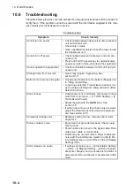
Page 136: ...w the plane area of the detection beam You can show the range rings on the detection beam concentrically Detectable Area Show the stereoscopic area of the detection beam 7 Select Quit then left click 8 If you selected Fan Shaped at step 6 select 2 Range Rings then left click For other settings go to step 11 9 Select ON or OFF then left click Select ON to show the range rings on the detection beam ...

Page 137: ... shape of the own ship mark 2 Display Size Select the scaling method for the own ship mark Scaled The size of the own ship mark changes ac cording to the zoom in out operation Fixed The size of the own ship mark is fixed 3 Color Select the display color for the own ship mark 4 Bow Line Show hide the bow line 5 Stern Line Show hide the stern line 6 Bow Stern Line Type Select the line type of the bo...

Page 138: ...mb line 4 Current Layer Mark Show hide the current layer mark Note 1 A current indicator is necessary to show the cur rent layer mark Note 2 The setting is shared with the Current Layer Mark ON OFF button on the 3D function panel Plumb line Plumb line Depth scale Depth scale 1 4R R display range 1 4R R display range Current layer mark Arrow s direction Indicates the direction of the tidal current ...

Page 139: ...nu 2 Select 7 3D Functions then left click 3 Select 8 Camera Operations then left click Menu item Description 1 Seabed detection Show hide the seabed Set this to OFF to hide the seabed echo on the 3D display 2 Detection threshold The higher the setting the strong color echo reddish brown red is recognized as the seabed 3 Seabed Echo Erasure Adjust the level of the seabed echo rejector The larg er ...

Page 140: ...tion 2 Swivel Direction Select the rotation direction for the auto swivel between the clockwise forward and counterclockwise reverse Forward The auto swivel direction is clockwise Reverse The auto swivel direction is counter clockwise Note The setting is shared with the Swivel Direc tion Forward Reverse button on the 3D function panel 3 Reset View Point Left click to reset the viewpoint position N...

Page 141: ...t from the center of the starboard side Stern Viewpoint from the center of the stern side 2 Custom View Point 1 View Point Selection Select the user programmed default position Default Use the factory default viewpoint as the user programmed default position The factory de fault is the viewpoint just above own ship Saved The viewpoint saved at 2 Save View Point is used for the user programmed defa...

Page 142: ...ist of destinations 7 Left click the Save button The progress bar advances as the saving progresses After the saving is completed the Setting File menu appears 8 Close the menu Note When there in not enough space on the drive to save the coefficient settings a minimum of 500 MB is required a warning message appears Click the Delete Data function to show the Delete Data window see section 8 8 then ...

Page 143: ... The selected file appears in the File Name box 7 Left click the Load button The progress bar shows the loading progress The Setting File menu appears when the loading is completed 8 Close the menu Note For the user custom view point following menu item the setting data is not ap plied after completing the loading The setting is applied at the next time the 3D mode is activated Main menu 7 3D Func...

Page 144: ...5 3D MODE 5 34 This page is intentionally left blank ...

Page 145: ...26m 12m Scan1 1 10 35 C 20min 10 0 12 10 8 2018 10 15 14 15 25 59t School INFO Length Width DIM Weight 51m 47m 2564m2 Requires appropriate data input See Appendix 3 See the fish histogram description in section 2 17 Water current speed and direction for three measuring layers Ship s position Latitude and longitude Net sonde depth data graph also available Fish histogram distribution graph Water te...

Page 146: ...ude and lon gitude If posi tion data is lost the last entered position is shown in red Lat 90 00 000S to 90 00 000N Lon 179 59 999W to 179 59 999E 180 00 00 0 00 000 L L Position sensor The position sensor type is displayed in brackets When the posi tion sensor is not connected nothing appears between the brackets DGPS KGPS FGPS GPS DR GPS DR AUTO System menu Depth Shows depth from transducer to b...

Page 147: ... axis C F Horizontal axis Time 20 min 1h 6h 12h 24h Vertical axis Temp 4 C 8 F fixed width auto shift C F Mark Data menu Info on school of fish Shows informa tion about school of fish captured by tar get lock Length Distance to school of fish in range direction Width Distance to school of fish in bearing direction Dimensions Dimension of the school of fish Weight Estimated tonnage of school of fis...

Page 148: ...6 NUMERIC GRAPHIC DATA DISPLAY 6 4 This page is intentionally left blank ...

Page 149: ...emote controller 7 1 User Menu Often used menu items can be registered to the User menu to enable quick access to those items The default menu items are TX pulse length TX power display color color response and echo average Left click to show the shortcuts Left click to show the shortcuts User menu items User menu items ...

Page 150: ...t click 4 Picture Setting to show the Picture Setting menu 3 Left click 2 Interference Reject Hold down the left button or scrollwheel more than one second to show the following message 4 Left click Register The selected item is registered and shown at the bottom of the menu The order of items in the User menu can be changed by drag and drop Note If 20 items are already registered to the User menu...

Page 151: ...function key 1 F1 to 0 F10 to show the applicable dialog box When the 7 F7 key is pressed 2 Press the same function key again within five seconds to execute the function The dialog box automatically disappears in five seconds You can also close the dialog box manually by pressing any function key other than the one pressed at step 1 Note You can change the location of dialog box that appears after...

Page 152: ...window and the indication is highlighted in light blue 2 Press desired function key for more than one second The message shown below appears for five seconds If the message disappears press the same function key again Note If the menu selected at step 2 is already programmed to a function key the following message appears for five seconds To continue the programming press the function key again wi...

Page 153: ...ck 7 Register to show the following menu 4 Left click 3 F Key List The items registered to the function keys appear 5 Click Confirm 6 Close the menu 7 2 4 How to erase programs 1 Open the menu 2 Left click 5 Record Recall Register 3 Left click 7 Register 4 Left click 4 Clear F Key Setting A confirmation message ap pears 5 Left click Changeable 6 Click the function key for which you want to erase i...

Page 154: ... P6 P7 P8 P9 P10 TX RX Setting menu 1 Transmission Interval 9 9 9 9 9 9 9 9 9 9 2 TX Pulse Length 9 9 9 9 9 9 9 9 9 9 3 Transmission Power 9 9 9 9 9 9 9 9 9 9 4 Reverbera tion 0 0 0 0 0 0 0 0 0 0 5 Frequency Shift 0 0 0 0 0 0 0 0 0 0 6 Band Width N N N N N N N N N W 7 Beam Width 3 3 3 3 3 3 3 3 3 3 Settings abbreviated as follows N Narrow W Wide Gain Setting menu 1 TVG Curve 35 35 35 35 35 35 35 3...

Page 155: ...rence Reject 2 2 2 2 2 2 2 2 2 2 3 INT Reject FF 6 6 6 6 6 6 6 6 6 6 4 Smooth Echo Range 1 1 1 1 1 1 1 1 1 1 5 Smooth Echo Circular 1 1 1 1 1 1 1 1 1 1 6 Auto Sweep Echo AVG 1 1 1 1 1 1 1 1 1 1 7 Auto Sweep INT REJ 2 2 2 2 2 2 2 2 2 2 8 Weak Echo Detection 1 1 1 1 1 1 1 1 1 1 9 2nd Echo Re ject 30 30 30 30 30 30 30 30 30 30 3D Function Echoes menu 2 Signal Level 5 5 5 5 5 5 5 5 5 5 3 Surface Noise...

Page 156: ...ick desired program no A checkmark 9 appears to the left of your selection You can program 10 settings P1 to P10 8 Click Quit on the setting box to close the box 9 Close the menu 7 4 Remote Controller option The keys of the remote controller can be reprogrammed with the functions of your choice 1 Open the menu 2 Left click 5 Record Recall Register 3 Left click 7 Register 4 Left click 6 Remote Key ...

Page 157: ...CUSTOMIZE THE SONAR 7 9 5 Left click the item 1 Ch1 to 6 Ch6 corresponding to the key whose setting you want to change 6 Left click the function to register 7 Left click Quit in the setting box 8 Close the menu ...

Page 158: ...7 HOW TO CUSTOMIZE THE SONAR 7 10 This page is intentionally left blank ...

Page 159: ...p up menu 3 Left click 4 Destination to Save to show the Destination to Save window 4 Left click Reference on the Destination To Save window Note Disk capacity of the D drive is subject to change 5 Specify the location where to save the still images and video files from the pull down menu 6 Left click OK 7 Close the menu Drop down list of destinations Left click Selected drive s used space and fre...

Page 160: ...uration select the monitor on which to capture the still image from the Still Image window For how to open the Still Image window see section 8 2 2 1 Open the menu 2 Left click 5 Record Recall Register 3 Left click 5 Record Still Image 4 To enter a comment check Add a Comment on the Still Image window A soft ware keyboard appears Enter your comment with the keyboard then left click Enter The pictu...

Page 161: ... section 8 1 Date and time are used for the name of the data automatically Still image yyyy_mm_dd_hh_mm_ss_comment jpg Setting data RECORD_yyyy_mm_dd_hh_mm_ss_comment dat Shown if you entered the comment 8 Left click Quit on the window to close the window 8 3 How to Display a Saved Still Image There are two ways to display saved still images Display the latest still image Display a still image fro...

Page 162: ...hard drive connected to the USB port on the Processor Unit 1 Open the menu 2 Left click 5 Record Recall Register 3 Left click 2 Motion Image 4 If two monitors are used select where to save the image 1 Main monitor 2 Sub monitor 5 Left click the button red to start the saving 6 To stop saving click the button red again The file is saved to the location specified in section 8 1 The file name is auto...

Page 163: ... Note 2 When there in not enough space on the drive to store more images approx 10 free space or less a warning message appears Click the Delete Data function to show the Delete Data window see section 8 8 then remove unnecessary files Repeat the above procedure when the drive has sufficient free space to save motion images ...

Page 164: ...from the file list 5 Left click the X button to start the playback Controls for stopping playback fast forwarding and rewind are provided on the Motion Image window 6 Left click Quit on the Motion Image Playback window to close the window 7 Left click Quit on the Motion Image window to close the window Drop down list of file names Drop down list of monitors Replay Movie GPS 891 289 Stop playback F...

Page 165: ..._yyyy_mm_dd_hh_mm_ss ini 5 Select where to save the setting data from the drop down list of destinations 6 Left click the Save button The progress bar advances as the saving progresses After the saving is completed the Setting File menu appears 7 Close the menu Note When there in not enough space on the drive to store a settings file approx 500MB is required a warning message appears Click the Del...

Page 166: ... setting information saved at section 8 6 1 Open the menu 2 Left click 5 Record Recall Register 3 Left click 8 Setting File 4 Left click 2 Load to show the Load window 5 Select the file to load from the destination list The selected file appears in the File Name box 6 Left click the Load button The progress bar shows the loading progress The Setting File menu appears when the loading is completed ...

Page 167: ...he Select User Program section left click the User Program to Load list 7 Left click the setting number to load 8 Left click the User Program to Set list 9 Left click the setting number to load the settings 10 Left click the Load button The progress bar shows the loading progress The Setting File menu appears when the loading is completed 11 Close the menu Drop down list of destinations Drop down ...

Page 168: ... show the Delete Data window 4 Select the file to delete The selected file appears in the File Name box 5 Left click the Delete button The message Are you sure to delete appears 6 Left click the OK button The file selected at step 4 is deleted 7 Left click the Cancel button to return to the 5 Record Recall Register menu 8 Close the menu Drop down list of destinations Drop down list of destinations...

Page 169: ...where to save the setting data from the drop down list of destinations 7 Left click the Save button The progress bar advances as the saving progresses After the saving is completed the Setting File menu appears 8 Close the menu Note The error message Disk space insufficient Delete unnecessary files appears if the save destination does not have sufficient space a minimum of 500MB is re quired If th...

Page 170: ...indow 6 Select the file to load from the drop down list of destinations The selected file ap pears in the File Name box 7 Left click the Load button The progress bar shows the loading progress 8 When the backed up data is loaded a completion message appears Restart the system to complete the procedure Drop down list of destinations Drop down list of destinations Progress bar Fills in blue color fr...

Page 171: ...tion 7 3 2 3 F Key List Show the function assigned to each function key See section 7 2 3 4 Clear F Key Setting Erase programs assigned to the function keys See section 7 2 4 5 Scan Range Presets the ranges to use with the RANGE control The setting range is 50 2000 m To set the ranges to use left click 5 Scan Range to display the window shown at the right Click a detection range to show a checkmar...

Page 172: ...rases event marks fish marks own ship position mark and track Note If 5 Monitor Setting on the Display Setting menu see page 9 12 is set to Sub Display or OFF all menu items on the Erase Marks menu are grayed out when the display mode is 3D 1 On the Mark Operation Support Tool menu left click 1 Erase Marks to show the Erase Marks menu 2 Left click one of the following 1 Erase All Erases all event ...

Page 173: ...wn ship tracks data temperature depth display on own ship track net movement prediction net move mark and fish tracks require ap propriate data input For details see DATA INPUT REQUIREMENTS on page AP 12 1 Heading Mark The heading mark is a dashed line which indicates the heading in all presentation modes It extends from own ship position to the out er edge of the display and appears at zero degre...

Page 174: ...vement against three current layers over time and requires the current tide data The plot is auto matically turned on or off with the net shoot mark The method for display ing the net shoot plot depends on the setting of 3 Net Plot CORR Layer1 through 7 Net Plot CORR Layer5 on the Net Shoot Setting menu see section 9 2 8 7 Fish Mark Connect You may connect fish marks with a line to show the order ...

Page 175: ...3 Target Lock Mark Sets the size of the target lock mark normal large or small 4 Target Vector You may display the target vector in short normal or long lengths Set long for slow moving target short for faster moving target 5 Event Mark Sets the size of the event mark normal large or small 6 Event Mark Sets the size of the fish mark normal large or small 7 Own Ship Position Mark Sets the size of t...

Page 176: ...peration Support Tool menu then select 4 Mark Data 1 Range Bearing Display Turns the range and bearing data on or off 2 Cursor Position Turns the cursor position latitude and longitude display on or off If position data is lost the cursor position indication becomes red Note 2 Cursor Position and 5 LAT LON in the Installation menu 9 Installa tion 6 External Data 5 LAT LON must be turned on to show...

Page 177: ...rt Tool menu then select 5 Current VEC Wind Current and wind data display require appropriate data input For details see DATA INPUT REQUIREMENTS on page AP 12 1 Current Data Selects how to display current data absolute or in relation to current layers 1 2 3 4 or 5 2 On Own Ship Mark Shows or hides the current mark shown on the own ship mark 3 On Ship Position Mark Shows or hides the current mark o...

Page 178: ...Sets the net diameter and net plotting correction values 3 Net Shoot Distance Sets the unit of measurement for net shoot distance nautical miles meters or feet 1 Net Diameter Sets net diameter in increments of 10 meters Setting range is 200 m to 1000 m 2 Tilt Interlock Turns on off interlocking of diameter of net course mark with tilt an gle 3 Net Plot CORR Layer1 7 Net Plot CORR Layer5 The moveme...

Page 179: ...the settings at 2 XMTR Distance to 0m then set the correct number of transmitters at 1 Number of XMTR 1 Number of XMTR Sets the number of transmitter units used from 0 to 10 When the total value of 2 XMTR Distance is smaller than the setting value of Net Length max 10 transmitter units can be used 2 XMTR Distance Sets the distance between transmitters Select this item then push the left click butt...

Page 180: ... echo color which triggers the fish alarm See section 2 15 2 3 Alarm Zone Sets fish alarm zone See section 2 15 1 4 Ship Speed Alarm The default setting is ON The alarm is released if ship s speed exceeds the following speeds Transducer in lowered position 18 kn Transducer in raised position 15 kn 5 Audio Turns the audio function on or off See section 2 14 1 6 Audio Gain Adjusts the volume of the ...

Page 181: ...nce To display the menu open the Installation Setting menu then select 1 Display Setting 1 Orientation Mode Selects the orientation mode among Head up North up Course up 2 Echo Display Area Selects the echo display mode Within Range or Full Screen 3 Full Screen Area Used when 2 Echo Display Area is set to Full Screen Ex pands the detection range and shows echoes outside the normal display area Op ...

Page 182: ...Display Main monitor Sub monitor Main monitor Sub monitor S Slant Slant Slant Slant VCS Vertical slant Vertical slant Vertical slant Vertical slant S FF Slant Fish finder Slant Fish finder Slant Fish finder VCS FF Vertical slant Fish finder Vertical slant Fish finder Vertical slant Fish finder 3D Slant 3D 3D Slant small 3D Slant small 3D S Slant 3D Slant 3D Slant 3D 3D FF Slant Fish finder 3D Not ...

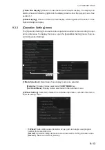
Page 183: ... ator s preference To display the menu open the Installation Setting menu then se lect 2 Operation Setting 1 Mode Selection Determines how display modes are selected 2 Wheel Setting Sets items related to scrollwheel operation Left click this item to show its setting menu Mode Key Display modes selected with DISP MODE key Pull Down Menu Display modes selected with the pull down menu 1 Wheel Sets se...

Page 184: ...ct to use the right button to enter marks fish mark 1 fish mark 2 event mark 1 event mark 2 fish estimate mark 1 fish estimate mark 2 2 Left Click Select to use the left button to enter marks fish mark 1 fish mark 2 event mark 1 event mark 2 fish estimate mark 1 fish estimate mark 2 0 1 Value changes in increments of 0 1 0 2 Value changes in increments of 0 2 0 5 Value changes in increments of 0 5...

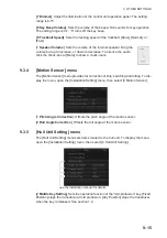
Page 185: ...menu The Motion Sensor menu provides for correction of ship s pitching and rolling To dis play the menu open the Installation Setting menu then select 3 Motion Sensor 1 Pitch Angle Correction Offsets the pitch angle at the motion sensor 2 Roll Angle Correction Offsets the roll angle at the motion sensor 9 3 5 Hull Unit Setting menu The Hull Unit Setting menu sets items related to the hull unit To ...

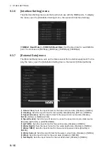
Page 186: ...ime data Disable or NMEA 2 Heading Sets the input format for the heading data Disable AD10 or NMEA 3 Speed Course Set the input format for the speed and course data Disable NMEA SOG or NMEA STW 4 Speed Sensor Sets the type of device to use as the speed and course data source Disable GPS DR or DOPPLER DR 5 LAT LON Sets the input format for the position data Disable or NMEA 6 Water Depth Sets the in...

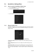
Page 187: ...nu open the Installation Setting menu then select 8 Initialization When 2 Item Attribution see below is set to Non Changeable a confirmation message ap pears Left click OK to access the menu 1 Language Sets the language to use 2 Item Attribution When a protected menu item in red is clicked you are asked if you want to display a confirmation message to enable settings changes However the menu items...

Page 188: ...uage IP address date and time oil replacement date motor running time to default settings When this item is clicked the confirmation message shown below appears Left click the Yes button the mes sage Press the power key to restart appears Restart the power to reset the system Note When the system is reset the default transducer position is restored and the message Register the transducer position ...

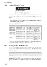
Page 189: ...ed Approximately once per year have a qualified technician check that the hull unit brake is working see section 10 11 3 Cleaning the equipment cabinet Dust or dirt can be removed from the equipment with a soft dry cloth Do not use chemical cleaners to clean the equipment they can remove paint and markings WARNING NOTICE Do not apply paint anti corrosive sealant or contact spray to plastic parts o...

Page 190: ...e are displayed according to the received data Note 1 When the voltage is 2 6V or less the error code 322 appears Have a qualified technician replace the battery Note 2 Dispose of the battery in accordance with local regulations Tape the and terminals of the battery before disposal to prevent short circuit which could cause a fire Unit Type Code No Remarks Processor unit Power cable FGBO A 125V 15...

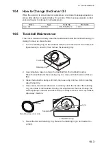
Page 191: ...ellophane tape to remove the trackball from the trackball housing Place the trackball and the retaining ring on a clean soft cloth laid on a flat sur face 3 Clean the ball with a damp soft cloth then use a dry lint free cloth to carefully wipe the ball dry 4 Use a swab moistened with water to carefully clean the inside of the retaining ring the inside of the trackball housing the supports and the ...

Page 192: ...o the bottom changes due to rolling and pitching Long range selected Transmission period is lon ger so ship s pitching and rolling are apt to affect detection of echo Weak echoes Output power set to minimum Set power to maxi mum from main menu 1 TX RX Setting 3 Transmission Power Adjust the gain with the GAIN knob See section 1 8 If either near echoes or far echoes only are weak adjust the Near Ga...

Page 193: ...ply OVERVOLTAGE Warning Meaning The voltage supplied to the transceiver unit is excessive Transmission is stopped if the equipment is transmitting to protect the transducer and transmitter power section from damage Remedy Silence the buzzer Retract the transducer and turn off the power Consult your local dealer for service Behavior The window stops flashing but remains on screen until the cause is...

Page 194: ...ETRACTED Warning Meaning The transducer is not raised within 16 seconds 800 mm stroke or 22 seconds 1100 mm stroke after pressing the key The LED keys next to the keys light up when this warning occurs Remedy Silence the buzzer The cause may be tangled nets bent shaft or a faulty raise unit Consult your local dealer for ser vice Behavior The window stops flashing but remains on screen until the ca...

Page 195: ...zer Lower the ship s speed Behavior The window disappears Alarm Meaning Ship s speed exceeded the threshold speed see section 9 2 9 when the transducer is being raised lowered Remedy Silence the buzzer Lower the ship s speed Behavior The window disappears Priority Message Remarks 1 TD IS A HALT CONDITION Remains on screen until the cause is removed or rectified 2 TRANSDUCER NOT RETRACTED Remains o...

Page 196: ...Meaning TX Off Transmission turned off from the menu main menu 8 Test 9 Transmission Unregistered The transducer position is not registered and cannot be displayed on screen Referring to the installation manual register the trans ducer position Raise Lower Test Raise lower command received from the control unit in normal operation to manually test raise lower switch in hull unit Raise lower keys o...

Page 197: ...er for advice Note Check that the system is correctly connected before doing any test 10 10 1 How to Use the test menu 1 Open the menu 2 Select 8 Test then left click Note If you are using 9 Transmission to determine a noise source be sure to set it back to ON after you have found the noise source The menu items ON No Charge and ON No Alarm should not be selected by the operator Left click Left cl...

Page 198: ... and status results ROM RAM Indicates the ROM and RAM status OK white text or NG red text B in PWR section Indicates B voltage 4 Hull unit control box information and status results OK Status is normal NG Error detected XX Program number OPERATION TEST Processor Unit Control Unit Press Menu Esc key to cancel 865 XXXX XX XX 105 XXXX XX XX Product Grade FSV 75 RAM OK EWF Enable MAC Address IP Addres...

Page 199: ...X board information and status results Results appears as OK white text or NG red text BOARD TEST TRCPU ROM OK RAM OK FRAM OK 105 XXXX XX XX Revision 0 105 XXXX XX XX Revision 0 TRX1 ROM OK RAM OK TFP OK T2S OK TRX3 TRX5 ROM OK RAM OK TFP OK T2S OK ROM OK RAM OK TFP OK T2S OK TRX2 TRX4 ROM OK RAM OK TFP OK T2S OK ROM OK RAM NG TFP OK T2S OK S2T OK RFP OK FFP OK S2R OK R2F OK HCTL 105 XXXX XX XX Re...

Page 200: ...d text 6 Motor test results Control Box TEST HCTL HMS SW Ver 105 XXXX XX XX CPLD Ver 105 XXXX XX XX PCB Ver 0 ROM OK RAM OK S1 0010 SW Ver 105 XXXX XX XX PCB Ver 0 ROM OK RAM OK S1 0000 HCTL HMS 24V OK 12V OK 5V OK 24V 23 8 Tacc 22 3ºC Tgyr 16 0ºC MOTOR HDRV CPLD Ver 105 XXXX XX XX PCB Ver 1 POWER SUPPLY 24 3V CURRENT 1 3A MOTION SENSOR MOTION SENSOR OFFSET INCLUDED Accel OK Gyro OK ROLL 8 9 PITCH...

Page 201: ...NU ESC key to close the results FAN MONITOR HCTL FAN0 Speed 8160rpm Control Box HCTL FAN1 Speed Reserve Transceiver Unit TRCPU FAN01 Speed 4200rpm TRCPU FAN02 Speed 4140rpm TRCPU FAN03 Speed Reserve TRCPU FAN04 Speed Reserve TRCPU FAN07 Speed Reserve TRCPU FAN05 Speed 3840rpm TRCPU FAN06 Speed 4080rpm Processor Unit CPU BOARD_FAN1 Speed 4000rpm Control box fans Transceiver unit fans Processor unit...

Page 202: ...crollwheel The indication shows a 1 pressed or 0 released if the scrollwheel is functioning cor rectly 2 Spin the scrollwheel upwards then downwards The indication shows a d if the scrollwheel is functioning correctly Knobs Turn each knob clockwise then counter clockwise The corresponding location on the test screen shows a positive val ue clockwise or negative value counter clockwise if the knob ...

Page 203: ...ever to the left then right then release the lever The corresponding location on the test screen shows a 1 pushed right up 2 pushed left down or 0 released if the lever is func tioning correctly Trackball 1 Move the trackball to the right the indication shows a positive value 2 Move the trackball to the left the indication shows a negative value 3 Move the trackball upwards the indication shows a ...

Page 204: ...t4 port5 GPZDA 054224 31 28 02 2020 80 00 61 GPVTG 0 0 T 90 0 M 10 0 N 0 0 K A 2B GPHDT 0 0 T 35 GPZDA 054223 29 28 02 2020 80 00 6F GPVTG 0 0 T 90 0 M 10 0 N 0 0 K A 2B GPHDT 0 0 T 35 GPZDA 054222 29 28 02 2020 80 00 6E GPVTG 0 0 T 90 0 M 10 0 N 0 0 K A 2B GPHDT 0 0 T 35 port2 Heading 25 Ship Course 5 Ship Speed 5 0kn LAT LON GPS 34 44 000N 135 21 000E Water Depth 321m Water TEMP 10 00 C Net Dept...

Page 205: ...at of SEATENDER 20 2 anti foulant to transducer face to keep marine life off the transducer Do not paint metallic parts such as the transducer flange Replace anti corrosion zinc plates yearly Replace anti corrosion zinc plates yearly Replace gasket if water is leaking from the main shaft Coat the drive shaft with Daphne Grease MP No 2 IDEMITSU KOSAN CO LTD 1 every six months Raise transducer and c...

Page 206: ...th the ratchet wrench see section 10 11 2 apply Molytone No 2 Grease How to grease the gear shaft Inject Daphne Grease MP No 2 to the grease nipple to grease the gear shaft Wing bolts Gear cover window Gear cover window Operation image Operation image Inject grease until a slight amount comes out here Inject grease until a slight amount comes out here Grease nipple Grease nipple ...

Page 207: ...over of the main shaft 1 Unfasten four hex head bolts to remove two seal support plates 2 Cut and remove the gasket 3 Take the spare gasket from the cover of the main shaft cover and set it to the main shaft 4 Fasten the two seal support plates removed at step 1 Hex head bolt Washer Seal support plate Main shaft cover MAIN SHAFT Spare gasket ...

Page 208: ...ace the anti corrosion zinc plates yearly Corrosion may result allowing water leakage and or loss of transducer The clearance between the hull and the ground or deck must be more than the amount listed below Tank guide 800 mm stroke 800 mm or more 1100 mm stroke 1100 mm or more Flange 800 mm 1100 mm stroke 650 mm or more Anti corrosion zinc plate Anti corrosion zinc plate Hex head bolt Tank guide ...

Page 209: ...n not check the LEDs continue to step 2 2 Turn off the switchboard transceiver unit and hull unit from the ship s mains breaker To force a system shut down press and hold the POWER ON I switch for ap proximately seven seconds 3 Check if the net or other object is caught in the transducer 4 Look through the lid on the raise lower control box in the hull unit to check if the motor breaker is OFF If ...

Page 210: ... While holding the ratchet wrench pull the release lever toward you and upward to release the brake Note Hold the ratchet wrench when releasing the brake to prevent the transduc er from falling 5 Turn the ratchet wrench counter clockwise to raise the transducer 6 After retracting the transducer into the tank set the release lever to the holder 7 Remove the ratchet wrench and return it to its holde...

Page 211: ...cuit is abnormal If the LED is OFF return the toggle switch to its original position and contact your dealer for advice 4 Set the toggle switch to the MBRAKE position Hold down the brake release push switch to release the motor brake Check that the main shaft does not lower and the 7 segment LEDs on the circuit board does not change If the main shaft lowers or the LED lighting pattern changes rele...

Page 212: ...he motor brake 1 Use cir clip pliers to release the two C clips one to either side of the brake 2 Pull the brake release lever to unlock the brake 3 Remove the brake release level with a set of pliers C clip locations C clips Brake release lever Lock ...

Page 213: ...move the fan 7 Unfasten both release plates one on either side with a hex wrench then remove the plates 8 Referring to the following figure unfasten the three screws then remove the wa terproofing cover and washer Brake release lever pin Brake release lever pin Bolt Bolt Remove brake cover Remove brake cover Fan bolt Fan bolt Release plate Release plate Screws ...

Page 214: ...rop the gap adjustment shim Gap gauge Leaf Loosen two wing screws to slide the cover and remove the gap gauge Measure gap here Moving core Fixed core Fixing plate Spacer Gap adjustment shim Bolt assy Hex bolts Hex bolts Fixed core Fixed core Gap Gap Spacer Spacer Moving core Moving core Hex bolt Hex bolt Fixing plate Fixing plate There is a chance to drop the shim when you remove the spacer Be sur...

Page 215: ...assemble the motor brake Note 1 Coat the hex bolt for the fan with thread locking fluid Note 2 Make sure that the holes on the release plates removed at step 7 are aligned with the holes on the waterproofing washer and the release plate fixing holes If the locking pins do not fit easily the holes may be mis aligned Check the alignment and re align as necessary Release plate fixing hole Release pla...

Page 216: ...10 MAINTENANCE 10 28 This page is intentionally left blank ...

Page 217: ...Yes 8 AGC Distance 20 to 2000 m 200 m S Yes F Yes 9 Noise Suppression 0 0 to 10 0 3 5 S Yes F Yes 0 Next 1 Seabed AGC 0 0 to 10 0 3 3 S Yes F Yes 1 Noise Limiter 0 to 10 S Yes F Yes 2 Signal Level 0 to 31 S Yes F Yes 3 Color Color 1 Color 2 Color 3 Color 4 S Yes F Yes 6 S Scan Color Curve Setting Display only S No F No 1 Echo Average 0 to 11 2 S Yes F Yes 1 Still Image S Yes F Yes 2 Motion Image S...

Page 218: ...Program P1 to P10 S No F No 3 F Key List F1 to F10 S No F No 4 Clear F Key Setting F1 to F10 S No F No 5 Scan Range 50m 100m 150m 200m 250m 300m 350m 400m 450m 500m 600m 700m 800m 1000m 1200m 1600m 2000m S No F No 7 Register S No F Yes 6 Fish Finder 1 Gain 0 0 to 10 0 5 0 S No F No S No F No 2 Range 16 to 3000 ft 200 ft S No F No 3 Shift 0 to 3000 ft 0 ft S No F No 4 Clutter 1 Clutter Leverl 0 to ...

Page 219: ...play S No F No 1 Beam Shape OFF Fan Shaped Detectable Area S No F No 2 Range Rings OFF ON S No F No 7 Own Ship Mark S No F No 1 Icon Type 1 Type 2 S No F No 2 Display Size Scaled Fixed S No F No 3 Display Color Red Blue Green White S No F No 4 Bow Line OFF ON S No F No 5 Stern Line OFF ON S No F No 6 Bow Stern Line Type Cylinder Line S No F No 7 Bow Stern Line Color Red Blue White S No F No 8 Plum...

Page 220: ...ation Mode Head Up North Up Course Up S No F No 2 Echo Display Area Within Range Full Screen S No F No 3 Full Screen Area 1 3R 1 6R 1 9R S No F No 4 TVG SIG Monitor TRANSP OFF ON S No F No 5 Monitor Setting S No F No 1 2nd Monitor Setting OFF Dual Display Sub Display S No F No 9 Installation Setting S No F No 8 Test S No F No 1 Operation Test S No F No 2 Board Test S No F No 3 Channel Test1 S No F...

Page 221: ...o 7 Own Ship Data S No F No 1 Date Time Disable NMEA S No F No 2 Heading Disable AD10 NMEA S No F No 3 Speed Course Disable NMEA S No F No 4 Speed Sensor Disable GPS DR Doppler DR S No F No 5 LAT LON Disable NMEA S No F No 2 Item Attribution Non Changeable Changeable S No F No 3 Reset User Program S No F No 4 Reset System S No F No 1 Language 㻌㻌㻌㻌㻌㻌㻌㻌㻌㻌 English Norsk Dansk Türk 䚷䚷 㻌㻌䚷䚷䚷 S No F No ...

Page 222: ... Mark OFF ON S No F No 3 On Ship Position Mark OFF ON S No F No 4 On Net Shoot Mark OFF ON S No F No 5 Current Flow Direction To From S No F No 6 Wind OFF Relative Absolute S No F No 1 Execute or Erase Execute Erase S No F Yes 3 Net Shoot Distance NM Meter Feet S No F No 2 Tilt Interlock OFF ON S No F Yes 3 Net Plot CORR Layer1 0 to 100 50 S No F No 4 Net Plot CORR Layer2 0 to 100 50 S No F No 5 N...

Page 223: ... No F No 9 Alarm Audio S No F No Shortcut Menu 4 Depth Display S1 S2 S3 S4 S5 S6 S7 S8 S9 S10 S No F No 7 Net Sonde Setting S No F No 1 Number of XMTR 0 to 10 3 S No F No 0 Next 1 Threshold 1 to 30 16 S No F No 4 Smoothing 0 0 to 1 0 0 5 S No F No 1 Fish Alarm OFF ON S No F No 2 Alarm Level S No F No 3 Alarm Zone S No F No 4 Ship Speed Alarm OFF ON S No F No 5 Audio OFF Audio1 Audio2 S No F No 7 A...

Page 224: ...is a problem with the hull unit Reset the system power 111 Hull Unit Controller COMM Error HCTL data communication error There is a communication problem between the hull unit and the processor unit Reset the system power 112 Hull Unit Controller Data Error HCTL data is over normal range 113 Hull Unit Controller Mal function Hull Unit Controller error There is a problem in the con trol box Reset t...

Page 225: ...out was detected in the hull unit motor Conduct the control box test see section 10 10 4 and check that the MO TOR SELF TEST item is not shown as NG Reset the system power 139 Motor Sensor Calibra tion Data Error Motor Sensor Calibration Data Error There is a problem in the mo tion sensor Reset the sys tem power Transceiver Unit 200 B Voltage Fault B voltage is over normal range An abnormal voltag...

Page 226: ...a input from TRX Board4 224 TRX Board5 COMM Er ror No data input from TRX Board5 243 RXBMF_FPGA Timeout No data input from PRETRG 244 FLT_FPGA Timeout No data input from PRETRG 245 12V voltage Malfunction 12V voltage is over normal range 248 PreLoader Error PreLoader program error There is a problem with the program inside the transceiv er Reset the system power Processor Unit 301 Processor Unit F...

Page 227: ...y in side the processor unit is low Consult your local dealer for battery replacement 323 NMEA Port Error NMEA port recognition er ror There was a problem detect ing the NMEA port Reset the system power 324 IP Address Conflict IP address conflict More than one connection has the same IP address Have your local dealer check that the IP addresses are set as follows Processor Unit 2 Transceiver Unit ...

Page 228: ...rk page 2 25 Estimate mark page 2 29 Fish mark page 2 31 Event mark page 2 33 Net Course mark page 2 35 Net Shoot mark page 2 36 Net Sonde mark page 2 36 Heading mark page 9 3 Bearing scale page 9 4 Tracks page 9 4 Fish tracks page 9 4 Net movement Net move plot page 9 4 Heading data Speed Course data Current data Current mark page 9 7 Wind related speed barbs etc page 9 8 Heading data Speed Cours...

Page 229: ... down the brake release push switch to release the motor brake 2 Measuring the gap in the motor brake 2 1 Insert the 0 6 mm leaf of the gap gauge 2 2 If the check item 2 1 is NG reduce the gap then check again Check that the Brake LED on the circuit board is lit in red Check that the main shaft does not lower and the 7 segment LEDs on the circuit board does not change Check that the 0 6 mm leaf ca...

Page 230: ...rtical combination scan Echo sounder combination Vertical and echo sounder combination FSV 75 3D only 3D single 3D combination 3D sounder combination for dual display 2 3 Marks Own ship Bow line Bearing Distance Event Fish school EBL Tracking Current Sonde 2 4 Information Scan Bearing Distance Cursor Distance Depth Bearing Event Fish school Position Bearing Own ship s location Speed Bearing Water ...

Page 231: ...evt fkv fmg fvc pidat sht tfm tlm tqm 5 POWER SUPPLY 5 1 Transceiver unit 100 110 115 220 230 VAC 2 5 A max 1 phase 50 60 Hz 5 2 Processor unit 12 24 VDC 4 0 2 0 A 5 3 Hull unit 200 220 VAC 4 A max 3 phase 50 60 Hz 5 4 Rectifier RU 1746B 2 option 100 110 115 220 230 VAC 1 phase 50 60Hz 6 ENVIRONMENTAL CONDITIONS 6 1 Ambient temperature Processor unit 15 C to 55 C Transducer 5 C to 35 C Transceiver...

Page 232: ... button 5 7 D Default View Point button 5 3 5 6 DELETE MARK key 2 32 2 34 Density CALC ON OFF button 5 7 Density calculation function calculation area 5 16 calculation area size setting 5 18 coefficient setting customize 5 18 coefficient settings backup 5 19 coefficient settings load 5 20 density information window 5 17 how to use 5 16 Depth and distance fish finder diplay 4 4 Depth scale 5 25 ver...

Page 233: ...lay 3 17 SIO test 10 14 Smoothing fish finder display 4 7 slant display 2 39 vertical slant display 3 20 Start sweep angle Tilt cross section mode 5 10 Start tilt angle Forward detection history mode 5 8 Tilt cross section mode 5 10 Status messages 10 8 STC fish finder display 4 7 Stern line 5 27 Surface noise rejectior 3D display 5 14 Swivel Direction Forward Reverse button 5 6 T Target fish mode...

Page 234: ...INDEX IN 3 W Warning messages 10 5 X XSECT ON OFF button 5 6 Z Zoom in out 5 4 ...

Page 235: ......

Reviews:

Related manuals for FSV-75