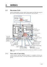
2. WIRING
2-9
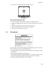
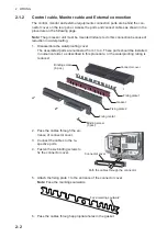
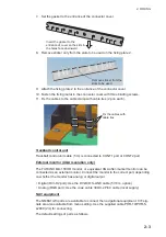
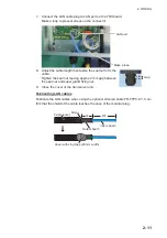
7. Connect the cable to the TB1 connector on the PWRTX board.
Confirm that the cores from the WAGO connector are not excessively bent.
8. Secure the shield and drain wires to the grounding terminal next to the connector.
See the figure at step 10 for details.
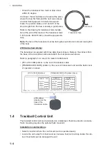
9. Attach the transducer sticker [FCV-2103 30M] to the transducer cable.
Refer to section 1.3 for sticker details.
10. Fix the cable to the plate with three cable saddles.
11. Re-assemble the seal assembly, then pack the seal assembly into the gland.
12. Fasten the seal-nut to secure the transducer cable.
Tighten the seal-nut leaving approx. 6 mm gap between
the seal-nut and the super-gland fixing nut.
13. Attach the [Transducer data] sticker on the rear side of
transceiver unit cover.
14. Close the cover of the transceiver unit.
Attach the sticker
[FCV-2103 30M] onto the
cable. (50 to 100 mm distance
from the super gland)
Fix the cable with cable
saddles (3 pcs).
Connect the WAGO
connector to TB1.
Terminal opener
Secure the shield
and drain wire
terminal lugs with
a screw.
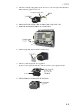
Position the cable so that
the cable end is directly
below this clamp.
Gap
LED
2
E
_
T
D
_
N
1
E
_
R
D
_
P
3
J4(NETWORK)
E
_
T
D
_
P
5
4
6
N
.C
.
N
.C
.
E
_
R
D
_
N
7 8
T
R
M
T
R
M
2
T
R
IG
_
IN
_
N
1
3
TB2(EXT-KP)
T
R
IG
_
IN
_
P
5
4
N
.C
.
02P6401
02P6400
02-172-1105-0
㓄⥺ࢩ࣮ࣝ
ON
S3
1
2
4
7
8
6
5
3
Reserved
Self mode
All Clear
ON
ON
ON
ON
ON
ON
ON
Reserved
Reserved
OFF
OFF
OFF
OFF
OFF
OFF
OFF
OFF
Reserved
Reserved
Reserved
CR28 ERROR
CR11 LINK
CR12 SPEED
CR25 KP
2
1
3
5
4
6
7
8
(TRANSDUCER)
TB1
MOD-Z072-050+ MPYCSLA-4 02CA10087-4PX25
MJ-A3SPF0013-035C
J4
LED
CR130 TX
CR7
CR21 5V_OVER_CUR
CR30 BVLT
(24 VDC)
J1
DANGER
High Voltage.
%9/7⾲グࡢ/('ࡢᾘⅉࢆ
㧗ᅽὀពࠋ
༴㝤
☜ㄆࡋ࡚ࡃࡔࡉ࠸ࠋ
CH1_TD_H
CH1_TD_L
CH2_TD_H
CH2_TD_L
CH3_TD_H
CH3_TD_L
CH4_TD_H
CH4_TD_L
BRN
RED
ORG
YEL
GRN
BLU
PPL
GRY
XDCR Ser.No.
PARAMETER 1
䝟䝷䝯䞊䝍
1
PARAMETER 2
䝟䝷䝯䞊䝍
2
㏦ཷἼჾ䝕䞊䝍
TRANSDUCER DATA
ୖ䛾䝕䞊䝍䜢䝯䝙䝳䞊䛻タᐃ䛧䛶䛟䛰䛥䛔䚹
SET ABOVE DATA ON MENU.
Attach the transducer
sticker onto the right of
shematic diagram.
Schematic
diagram
Summary of Contents for FCV-2100
Page 6: ...EQUIPMENT LISTS iv This page is intentionally left blank...
Page 14: ...1 MOUNTING 1 8 This page is intentionally left blank...
Page 46: ...3 INITIAL SETTINGS 3 18 This page is intentionally left blank...
Page 52: ...16 Nov 2015 H MAKI 16 Nov 2015 H MAKI...
Page 53: ...17 Nov 2015 H MAKI 17 Nov 2015 H MAKI...
Page 54: ...26 Feb 2016 H MAKI 26 Feb 2016 H MAKI...
Page 55: ...17 Nov 2011 Y NISHIYAMA 17 Nov 2011 Y NISHIYAMA...
Page 56: ...17 Nov 2011 Y NISHIYAMA 17 Nov 2011 Y NISHIYAMA...
Page 57: ...17 Nov 2011 Y NISHIYAMA 17 Nov 2011 Y NISHIYAMA...
Page 58: ...8 Mar 2016 H MAKI...

