1. MOUNTING
1-6
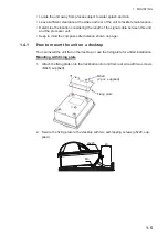
Surface mounting
1. Drill four holes (
I
4) on the table re-
ferring to the outline drawing at the
back of this manual.
2. Secure the trackball control unit with
four screws (M3, local supply) from
the underside of the table.
The length of screws should be de-
termined depending on the thick-
ness of panel. Refer to the outline
drawing at the back of this manual.
1.4.2
How to mount the unit in a console panel
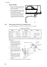
Use the optional flush mount kit OP14-70 to install the unit in a console.
Flush mount kit OP14-70
Note:
Do not mount the trackball control unit on a inclined surface, as drainage may
be prevented.
1. Prepare a cutout in the in-
stallation location. Refer to
the outline drawing at the
back of this manual for the
cutout dimensions.
2. Set the unit to the cutout.
3. Attach the mounting plate
to the unit with four screws
(M3x8, supplied) from rear
side.
4. Screw the wing bolts and
the wing nuts so that the
protectors for the screws
move to the flush mount
assembly.
5. Fasten each wing bolt and then fasten each wing nut.
Name
Type
Code No.
QTY
Remark
SEMS B screw
M3 x 8
000-162-649-10
4
FM1 assy.
OP14-70-1
001-133-860
2
w/ wing bolt/nut
FM2 assy.
OP14-70-2
001-133-870
2
w/ wing bolt/nut
FM1 fixture
14-078-2301-1
100-364-711-10
2
Spare
180
72
114
40
φ
4
M3
FM1 assy.
FM2 assy.
M3x8 (4 pcs.)
Wing bolt
Wing nut
Summary of Contents for FCV-2100
Page 6: ...EQUIPMENT LISTS iv This page is intentionally left blank...
Page 14: ...1 MOUNTING 1 8 This page is intentionally left blank...
Page 46: ...3 INITIAL SETTINGS 3 18 This page is intentionally left blank...
Page 52: ...16 Nov 2015 H MAKI 16 Nov 2015 H MAKI...
Page 53: ...17 Nov 2015 H MAKI 17 Nov 2015 H MAKI...
Page 54: ...26 Feb 2016 H MAKI 26 Feb 2016 H MAKI...
Page 55: ...17 Nov 2011 Y NISHIYAMA 17 Nov 2011 Y NISHIYAMA...
Page 56: ...17 Nov 2011 Y NISHIYAMA 17 Nov 2011 Y NISHIYAMA...
Page 57: ...17 Nov 2011 Y NISHIYAMA 17 Nov 2011 Y NISHIYAMA...
Page 58: ...8 Mar 2016 H MAKI...

