2. WIRING
2-2
2.1.2
Control cable, Monitor cable and External connection
The control, monitor and external equipments connection ports are behind the con-
nector cover on the rear panel. Access the ports and connect cables as shown in the
procedure on the following page.
Note:
The processor unit must be mounted indoors to do this connection because of
reduction in waterproofing.
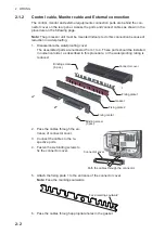
1. Disassemble the waterproofing cover.
The assembled parts are numbered from 1 to 4. These parts should be installed
in numerical order, as described in this procedure, or the waterproofing rating is
reduced.
2. Pass the cables through the en-
trance of connector cover.
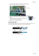
3. Connect the cables to the re-
spective ports.
4. Fasten the six binding screws to
fix the connector cover.
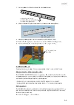
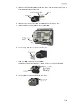
5. Attach the fixing plate 1 to the entrance of the connector cover.
Note:
Face the markings outwards.
6. Pass the cables through appropriate holes in the gasket.
Connector cover
Binding screw
(6 pcs.)
Binding screw
(3 pcs.)
Fixing plate 1
Fixing plate 2
Fixing metal
Gasket
Connector cover
Path the cables through the connector
Face markings outward
Summary of Contents for FCV-2100
Page 6: ...EQUIPMENT LISTS iv This page is intentionally left blank...
Page 14: ...1 MOUNTING 1 8 This page is intentionally left blank...
Page 46: ...3 INITIAL SETTINGS 3 18 This page is intentionally left blank...
Page 52: ...16 Nov 2015 H MAKI 16 Nov 2015 H MAKI...
Page 53: ...17 Nov 2015 H MAKI 17 Nov 2015 H MAKI...
Page 54: ...26 Feb 2016 H MAKI 26 Feb 2016 H MAKI...
Page 55: ...17 Nov 2011 Y NISHIYAMA 17 Nov 2011 Y NISHIYAMA...
Page 56: ...17 Nov 2011 Y NISHIYAMA 17 Nov 2011 Y NISHIYAMA...
Page 57: ...17 Nov 2011 Y NISHIYAMA 17 Nov 2011 Y NISHIYAMA...
Page 58: ...8 Mar 2016 H MAKI...

