background image

Chapter 9  Connectivity Management
 9.2  Functions in the Action Area for Connectivity

ETERNUS Web GUI User’s Guide

313

Copyright 2011 FUJITSU LIMITED

P2X0-1090-02ENZ0

9.2.2.6

Modify FC Host Group

This function performs the following modifications to the existing FC host group.

Host Group Name

Host Response

Number of Hosts (Add and delete member hosts in a host group)

Hosts can be added to host groups which the host affinity setting has been already configured, or
deleted from host groups.
If a host is added, the host affinity setting is automatically configured to the host, as a host group
member.
If a host is deleted, the host affinity setting is cleared from the corresponding host.

The maximum number of connectable hosts (the number of HBAs) per device is 1024, 
irrespective of the interface types.

The maximum number of connectable hosts (the number of HBAs) per CA port is 256.

The maximum number of connectable hosts (the number of HBAs) per host group is 8.

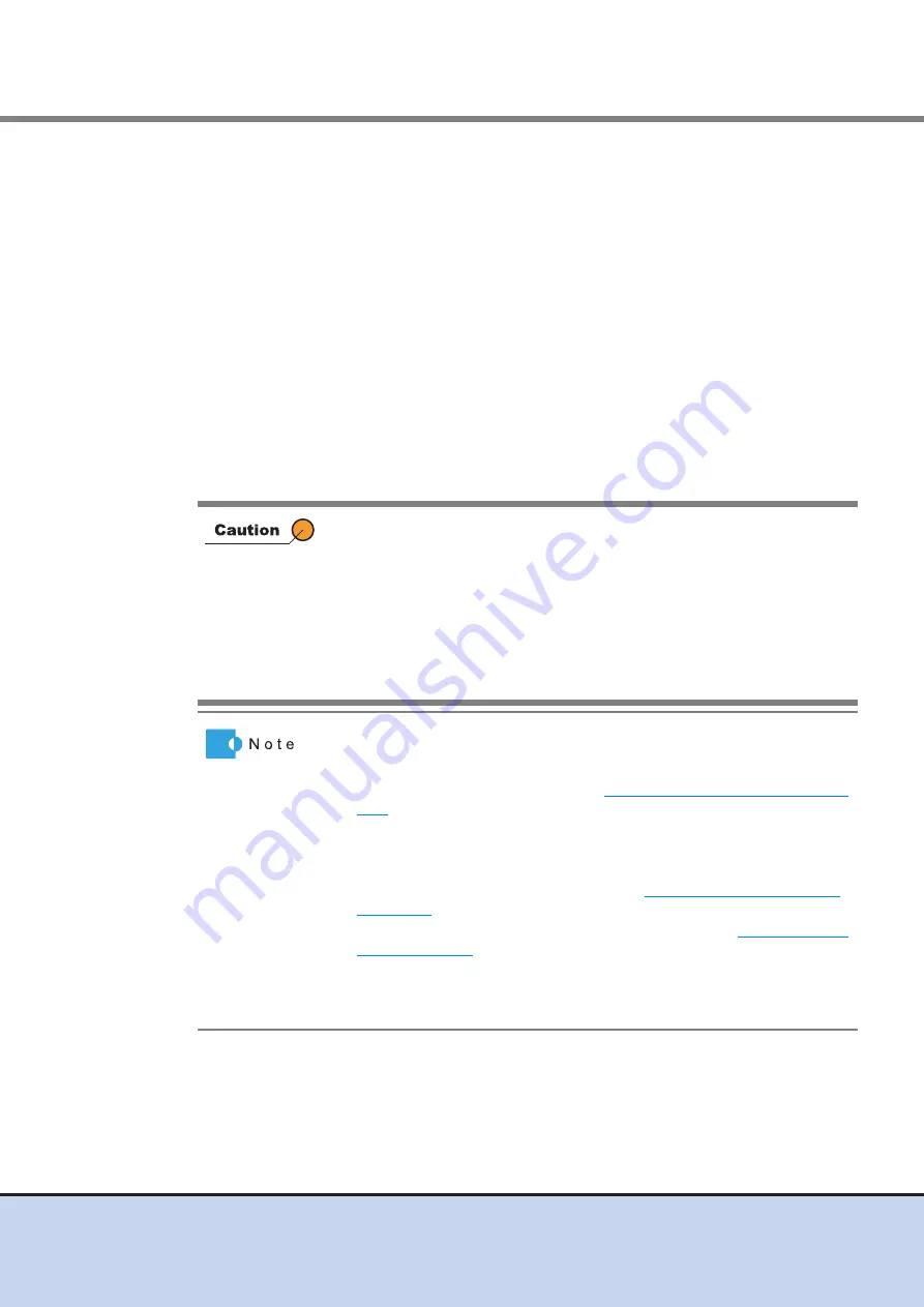
Registration of the host is necessary to create a host group. Not all of
the hosts can be deleted from a host group. A host, which has been
registered on GUI, belongs to one of the host groups.

One host cannot be a member of several host groups.

Assign an appropriate host response to the host group. The host
response configures the operation mode which is appropriate to the
host. If an appropriate host response is not configured to the host group,
the path may not be switched correctly or the volume may not be
recognized correctly.

When a host was added to a host group, of which the host affinity
setting has been configured, paths between all the ports with the host
affinity setting and the added host will be configured. To modify the path
between a host and a port, refer to 

"9.2.1.3 Modify Host Affinity" (page

290)

.

When a host in the host group for which the host affinity settings are
already configured is deleted, the path from the host to the port is also
deleted.

To change the host group names, refer to 

"9.2.2.12 Rename FC Host" 

(page 333)

.

To create a new host group and register hosts, refer to 

"9.2.2.1 Add FC

Host" (page 295)

.

A FC host and an FCoE host can be members of the same host group.
Both "FC host" and "FCoE host" are abbreviated as "FC host" in this
guide.

Summary of Contents for Eternus web GUI

Page 1: ......

Page 2: ...This page is intentionally left blank ...

Page 3: ...dixes Chapter 1 Outline This chapter describes the outlines features operation environment user management function and operation screens for Web GUI Chapter 2 Startup and Shutdown This chapter describes how to start exit log in and log out from Web GUI Chapter 3 Initial Setup This chapter describes the initial settings for the ETERNUS DX Disk storage systems Chapter 4 Configuration Settings This ...

Page 4: ...bout the ETERNUS DX Disk storage systems is released in the following web site Access the following address if needed URL http www fujitsu com global services computing storage eternus documentation Related Documents Other documents for the ETERNUS DX80 S2 DX90 S2 and ETERNUS DX410 S2 DX440 S2 are as follows ETERNUS DX80 S2 DX90 S2 Disk storage system Overview ETERNUS DX80 S2 DX90 S2 User s Guide ...

Page 5: ...and Egenera PAN Manager are trademarks or registered trademarks of Egenera Inc in the USA and other countries VERITAS Volume Manager is a trademark of Symantec Corp and its affiliated companies Other company names product names and service names are registered trademarks or trademarks of their respective owners Naming Conventions Product names The following products will be represented throughout ...

Page 6: ...at 1KB 1 000 bytes 1MB 1 000KB 1GB 1 000MB and 1TB 1 000GB example 600GB drive Other logical capacities for RAID Groups and volumes assume that 1KB 1 024 bytes 1MB 1 024KB 1GB 1 024MB and 1TB 1 024GB Note that the screen shots in this manual were captured during development of the software and the actual screens may be different Screen shot s reprinted with permission from Microsoft Corporation Co...

Page 7: ...2 2 Login 27 2 3 Logout 29 2 4 Exit 30 Chapter 3 Initial Setup 31 3 1 Initial Setup 1 32 3 2 Initial Setup 2 42 Chapter 4 Configuration Settings 54 4 1 Configuration Settings for Using Standard Volumes 54 4 2 Configuration Settings for Using Thin Provisioning Functions 57 Chapter 5 Volume Management 58 5 1 Volume Status 58 5 1 1 Volume Basic Information 58 5 1 2 Performance Host I O 60 5 1 3 Perfo...

Page 8: ...9 Release Reservation 104 5 2 20 Start Balancing Thin Provisioning Volume 105 5 2 21 Stop Balancing Thin Provisioning Volume 107 Chapter 6 RAID Group Management 109 6 1 RAID Group Status 109 6 1 1 RAID Group Basic Information 109 6 1 2 RAID Group Tuning 111 6 1 3 RAID Group ECO Mode 113 6 1 4 RAID Group Volume Layout 115 6 1 5 RAID Group Disk 116 6 2 Functions in the Action Area for RAID Group 117...

Page 9: ...Remote Copy 179 8 1 4 Setting 183 8 1 5 Advanced Copy Property 191 8 1 6 Advanced Copy Extent information 194 8 1 7 Copy Path Details 195 8 2 Functions in the Action Area for Advanced Copy 197 8 2 1 Start SnapOPC 199 8 2 2 Stop Session 202 8 2 3 Register Advanced Copy License 202 8 2 4 Delete Advanced Copy License 205 8 2 5 Modify EC OPC Priority 205 8 2 6 Modify Copy Table Size 207 8 2 7 Modify C...

Page 10: ...10 1 4 Disks 410 10 1 5 Controller Module Detail 414 10 1 6 Channel Adapter Detail 416 10 1 7 PSU CPSU CE Detail 419 10 1 8 Drive Enclosure Detail 420 10 1 9 I O Module Detail 424 10 1 10Power Supply Unit DE Detail 426 10 1 11Disks Detail 427 10 2 Functions in the Action Area for Component 430 10 2 1 Add Drive Enclosure 430 10 2 2 Turn on Locator Beacon Turn off Locator Beacon 432 10 2 3 Add Chann...

Page 11: ... 1 Roles 592 A 2 Availability of Functions for each Policy 593 Appendix B Status List 612 B 1 Device General Status 612 B 2 Volume Status 613 B 3 RAID Group Status 614 B 4 Thin Provisioning Pool Status 615 B 5 Component Status 615 B 5 1 Drive Status 616 Appendix C Naming Conventions of Volumes and Hosts 617 C 1 Naming Convention of Volumes 617 C 2 Naming Convention of Hosts 618 C 2 1 For FC Hosts ...

Page 12: ...er 1 1 Outline Use GUI to set the operating environment and check status for the ETERNUS DX Disk storage system GUI can be operated from a web browser by connecting the PC via a LAN connection Refer to Chapter 2 Startup and Shutdown page 25 for details of GUI start up LAN PC Web Browser Management Server Mail Server Program 1 1 Connect the operation server and the ETERNUS DX Disk storage system Op...

Page 13: ...ngs that are required to run the ETERNUS DX Disk storage system Status Display This function displays the device installation image Checking the extent of a failure If a drive failure occurs host port LUN group volume RAID group and installation location can be referenced to determine the extent of the failure Easy operation If a hardware failure is detected the system administrator can receive a ...

Page 14: ... tab Disable the Show friendly HTTP error messages under the Internet Options Advanced tab Furthermore when using ETERNUSmgr with Microsoft Internet Explorer 8 0 note the following Enable Automatic prompting for file downloads and Allow websites to open windows without address or status bars under the Internet Options Security tab Disable the SmartScreen Filter in the Tools menu or disable the Sma...

Page 15: ...hat are allowed for each user For normal operation of the ETER NUS DX Disk storage system apply the Admin default role for the system administrator and apply the Maintainer default role for the maintenance engineer Operation mistakes and maintenance worker hours can be reduced and device security can be improved by placing the authorized functions of system administrators in units of usage and by ...

Page 16: ...the ETERNUS DX Disk storage system and the usage of RAID groups Thin Provisioning Pools TPP and Snap Data Pools SDP can be checked in this screen The Initial Setup screen is displayed for the first login after installation of the ETERNUS DX Disk storage system is complete Be sure to log out after all necessary operations are completed If the operation screen is not updated when accessing the GUI c...

Page 17: ...in normal status is displayed Warning Modules The number of components in warning status 1 is displayed Disks The number of drives in warning status is displayed Error Modules The number of components in error status 1 is displayed Disks The number of drives in error status is displayed 1 The number of components that can be maintained The number of components does not include the number of drives...

Page 18: ...tors are displayed The factors of the Write Through Mode are described below Write Through Pinned Data A large amount of pinned data 1 occurred in the ETERNUS DX Disk storage system Write Through Battery The battery charge level is low Write Through Maintenance The following maintenance operation is currently being used Switch Controller Firmware Change Controlling CM Add Controller Module 1 Pinne...

Page 19: ...onfigure TPPs and the capacity of RAID groups that are registered as REC Disk Buffers Total Capacity The total capacity of the RAID groups MB GB TB is displayed The Total Capacity is the total capacity of all the RAID groups in the ETERNUS DX Disk storage system This value does not include the capacity of RAID groups that configure TPPs and the capacity of RAID groups that are registered as REC Di...

Page 20: ...p Data Pool Count The number of SDPs that are registered in the ETERNUS DX Disk storage system is displayed Total Used Capacity The total used capacity of the SDP MB GB TB is displayed The Total Used Capacity is the total capacity of all the SDPs that are used for volumes Total Free Capacity The total free capacity of the SDP MB GB TB is displayed The Total Free Capacity is the total unused capaci...

Page 21: ... DX Disk storage system Status of each component in the ETERNUS DX Disk storage system is monitored periodically and the result is displayed as a general status icon with character strings Refer to B 1 Device General Status page 612 for details about the general status Navigation Overview Volume RAID Group Thin Provisioning Advanced Copy Connectivity Component and System tabs are displayed Click t...

Page 22: ... only the items meeting all the specified conditions The conditions that are available depend on the function No filtering is set by default Action Only the available functions for the selected items from the navigation or in the category are dis played Click the function that is to be used to display the wizard screen Clicking the button switches the display of action area 1 5 3 List Screen Detai...

Page 23: ...that are displayed to switch the display 1 5 4 Basic Operation Select the desired item and execute the selected operation For some items the same information may be displayed for the list screen and the detailed screen From Chapter 5 onward only the information for items in the detailed screen that is different from the list screen is described Tabs to change detailed screens Filter setting Sortin...

Page 24: ... ascending order A Z or 0 9 in descending order Z A or 9 0 or in a specific order Clicking the sorting criteria changes the order The item that is furthest to the left is displayed in ascending order by default Select all checkbox The Select All checkbox is the first item in the left of the item field Click this checkbox to select all of the checkboxes that are listed This checkbox is left clear b...

Page 25: ...the login screen via the web browser The procedure to start up the login screen for GUI is as follows Procedure 1 Directly connect the PC and MNT port of the ETERNUS DX Disk storage system via LAN cable 2 Set the IP address and subnet mask for the PC to match the ETERNUS DX Disk storage system network settings 3 Enter http IP address of the device to the address bar in the web browser Default IP a...

Page 26: ...ter SSL Certificate page 497 To obtain the Self signed SSL Certificate use the procedure in 11 2 3 15 Create Self signed SSL Certificate page 490 and register the created Self signed SSL Certificate in the ETERNUS DX Disk storage system Refer to Appendix D Installing the Security Certificate page 622 for details on how to register the Self signed SSL Certificate If Firefox 3 6 x is used for connec...

Page 27: ...guage English or Japanese 2 Enter the User ID and Password and click the Login button The User ID and the Password vary depending on which account is being used to log in User ID root Password root Default The operation screen appears If a login is attempted while 16 users are already logged in to the GUI an error screen appears When this occurs note the error message and try logging in again afte...

Page 28: ...hat are logged from CLI is not included Logging in 17 or more users is not allowed Also note that when another user is already logged in and performing one of the following operations a warning message appears and some functions cannot be used Confirm the current GUI usage state and start operation When applying controller firmware When applying disk firmware During the RAID group diagnosis During...

Page 29: ...ion screen appears 2 Click the OK button This completes the logging out process The login screen appears End of procedure A logout is performed automatically under the following conditions When a different user executes a forcible logout 1 When the ETERNUS DX Disk storage system is turned off When no operation is performed for 60 minutes or longer after logging in 1 When the user name is the same ...

Page 30: ...NZ0 2 4 Exit Exit from GUI The procedure to exit is as follows Procedure 1 Click the Close button for the web browser Exit from GUI The login screen does not appear End of procedure Make sure to perform 2 3 Logout page 29 operation before exiting GUI If exiting GUI without logging out the login status is not released ...

Page 31: ...um settings required before using the ETERNUS DX Disk storage system Initial Setup 2 Makes the reporting settings for when an error occurs in the ETERNUS DX Disk storage system The settings can be omitted if the reporting function will not be used If the browser is shut down during execution of Initial Setup other functions will no longer be available If this case forcibly log in using the same us...

Page 32: ...r details 4 Register Thin Provisioning License If using the Thin Provisioning function register the license here Refer to 7 2 9 Register Thin Provisioning License page 168 for details 5 Register Copy License If using the Advanced Copy function register the license here Refer to 8 2 3 Register Advanced Copy License page 202 for details 6 Register SED Authentication Key Register the SED Authenticati...

Page 33: ... Copyright 2011 FUJITSU LIMITED P2X0 1090 02ENZ0 The procedure to perform Initial Setup 1 is as follows Procedure 1 Click Start Initial Setup in Action 2 Click the Next button Initial Setup starts The Start Initial Setup screen is displayed after logging in for the first time ...

Page 34: ... click the Next button Name Installation Location Administrator Description A confirmation screen appears 3 2 Click the OK button Setting of the storage system name starts 3 3 Click the Done button If logging in for the first time be sure to set the name of the ETERNUS DX Disk storage system If not logging in for the first time click the Skip button to proceed to the next screen without setting ...

Page 35: ...oceed to Set Date and Time 4 1 Specify the following items and click the Next button Date Time Information Time Zone Daylight Saving Time NTP Service A confirmation screen appears 4 2 Click the OK button Setting of the Date time starts 4 3 Click the Done button Click the Skip button to proceed to the next screen without setting ...

Page 36: ...2ENZ0 5 Proceed to Change Password 5 1 Specify the following items and click the Next button Old Password New Password Confirm New Password A confirmation screen appears 5 2 Click the OK button Changing of the password starts 5 3 Click the Done button Click the Skip button to proceed to the next screen without setting ...

Page 37: ... 1 Specify the following items and click the Next button License Key if not already registered A confirmation screen appears 6 2 Click the OK button Thin Provisioning license is registered 6 3 Click the Done button If the Thin Provisioning license key is already registered proceed to Register Copy License Click the Skip button to proceed to the next screen without setting ...

Page 38: ...icense Key A confirmation screen appears 7 2 Click the OK button The Advanced Copy license registration is executed 7 3 Click the Done button If a Advanced Copy license trial license is already registered the paid license can be registered Enter the license key If the Advanced Copy license key paid license is already registered proceed to Register SED Authentication Key Click the Skip button to pr...

Page 39: ...o Register SED Authentication Key 8 1 Click the Next button A confirmation screen appears 8 2 Click the OK button SED Authentication Key registration starts 8 3 Click the Done button If the SED Authentication Key is already registered proceed to Set Network Environment Click the Skip button to proceed to the next screen without setting ...

Page 40: ...Network Environment 9 1 Specify the following items and click the Next button Select Network Port Interface Allowed IP List A confirmation screen appears 9 2 Click the OK button Setting of the network environment starts 9 3 Click the Finish button A completed screen appears Click the Skip button to proceed to the next screen without setting ...

Page 41: ...Initial Setup 1 is complete End of procedure Follow the on screen instructions to reboot the ETERNUS DX Disk storage system if needed Restart the browser and wait a few minutes before logging into the Web GUI again After logging in again continue with the initial setup Proceed to Initial Setup 2 After logging in again continue with the initial setup Proceed to Initial Setup 2 ...

Page 42: ...Setup SNMP Agent MIB Access View page 468 for details 4 Set SNMP Agent User Set up the user which accesses the SNMP Agent The security level and the MIB access range are configured for each user Refer to 11 2 3 6 Setup SNMP Agent User page 471 for details 5 Set SNMP Agent Community Set up the SNMP Agent Community Refer to 11 2 3 7 Setup SNMP Agent Community page 474 for details 6 Set SNMP Agent Tr...

Page 43: ...perform Initial Setup 2 is as follows Procedure 1 Click Start Initial Setup in Action 2 Click the Next button Initial Setup restarts When logging in again after Initial Setup 1 is complete the Initial Setup 2 screen appears If all of the settings of Initial Setup 2 are not performed click the All Skip button to exit the Initial Setup wizard ...

Page 44: ...o Set SNMP Agent Basic 3 1 Specify the following items and click the Next button SNMP Function LAN Port used for SNMP Authentication Failure Engine ID A confirmation screen appears 3 2 Click the OK button Setting of the SNMP Agent basic starts 3 3 Click the Done button Click the Skip button to proceed to the next screen without setting ...

Page 45: ... Set SNMP Manager 4 1 Click the Add button 4 2 Set the IP address of the SNMP Agent Manager and click the OK button Return to the original screen 4 3 Repeat Step 4 1 and Step 4 2 to configure multiple IP addresses 4 4 When the IP addresses are set click the Next button Click the Skip button to proceed to the next screen without setting ...

Page 46: ...ENZ0 A confirmation screen appears 4 5 Click the OK button Setting of the SNMP Agent Manager starts 4 6 Click the Done button 5 Proceed to Set SNMP Agent MIB View 5 1 Click the Add button 5 2 Specify the following items and click the OK button View Name Click the Skip button to proceed to the next screen without setting ...

Page 47: ...ginal screen 5 3 Repeat Step 5 1 and Step 5 2 to configure multiple MIB Access Views 5 4 When the setting of the MIB Access Views is complete click the Next button A confirmation screen appears 5 5 Click the OK button Setting of the SNMP Agent MIB Access View starts 5 6 Click the Done button 6 Proceed to Set SNMP Agent User 6 1 Click the Add button ...

Page 48: ...urn to the original screen 6 3 Repeat Step 6 1 and Step 6 2 to configure information for multiple users 6 4 When the setting of the user information is complete click the Next button A confirmation screen appears 6 5 Click the OK button Setting of the SNMP Agent User starts 6 6 Click the Done button 7 Proceed to Set SNMP Agent Community 7 1 Click the Add button The Set SNMP Agent User function mus...

Page 49: ...OK button Community Name View Name Allowed SNMP Manager List Return to the original screen The Set SNMP Agent Community function must be set when using SNMPv1 or SNMPv2c in SNMP communication between the SNMP Agent and SNMP Agent Manager The SNMP Community setting is not necessary when using SNMPv3 only Click the Skip button to proceed to the next screen without setting ...

Page 50: ... of the community is complete click the Next button A confirmation screen appears 7 5 Click the OK button Setting of the SNMP Agent Community starts 7 6 Click the Done button 8 Proceed to Set SNMP Agent Trap 8 1 Click the Add button 8 2 Specify the following items and click the OK button Manager No SNMP Version Community Name User Name Port No Click the Skip button to proceed to the next screen wi...

Page 51: ...o configure information for multiple traps 8 4 When the setting of the trap information is complete click the Next button A confirmation screen appears 8 5 Click the OK button Setting of the SNMP Agent Trap starts 8 6 Click the Done button 9 Proceed to Set E mail Notification 9 1 Specify the following items and click the Next button Notification E Mail Mail Server Settings Retry Setting ...

Page 52: ...firmation screen appears 9 2 Click the OK button Setting of the E Mail Notification starts 9 3 Click the Done button 10 Proceed to Set Syslog Notification 10 1 Specify the following items and click the Next button Send Log Domain Name IP Address Port No LAN Port Click the Skip button to proceed to the next screen without setting ...

Page 53: ... FUJITSU LIMITED P2X0 1090 02ENZ0 A confirmation screen appears 10 2 Click the Finish button A completed screen appears 11 Click the Finish button Initial Setup 2 is complete and the Overview screen appears End of procedure Click the Skip button to proceed to the next screen without setting ...

Page 54: ... following section describes the series of settings when using Standard volumes Not only can new RAID groups be created adding or changing volumes that are registered in existing RAID groups can also be performed Create RAID Group Create a RAID group a group of drives that configures the RAID in the ETERNUS DX Disk storage system Refer to Create RAID Group Create Volume Create a volume drive area ...

Page 55: ...t are connected to the specified host group that is used for the server to access the server Refer to Create FC Port Group Create iSCSI Port Group Create SAS Port Group Create FCoE Port Group Add LUN Group Create a LUN group a group of volumes that are recognized from the server which is conventionally referred to as an Affinity group Correspond the volume number to the Logical Unit Number LUN tha...

Page 56: ... or allocate the host groups with the LUN groups When only a specific host group recognizes the LUN group Select the specific host group and allocate the port group and the LUN group host affinity setting When all of the hosts that are connected to the specific port group recognize the LUN group Select All for the host group and allocate the port group and the LUN group the host affinity setting t...

Page 57: ...egister Thin Provisioning License Register the license to use the Thin Provisioning function Refer to Register Thin Provisioning License Create Thin Provisioning Pool Create a Thin Provisioning Pool groups of drives which are configured in RAID groups that configure a Thin Provisioning Pool Refer to Create Thin Provisioning Pool Create Volume Create a volume physical drive area in the Thin Provisi...

Page 58: ...ys the following status information Volume Basic Information Performance Host I O Performance Advanced Copy Reservation Pinned Data Bad Sector Balancing Thin Provisioning Volume Detailed information of the volumes can be displayed from the following screens Volume Pinned Data Volume LUN Concatenation 5 1 1 Volume Basic Information This function displays the basic information of volumes ...

Page 59: ...ed for general operations SDV Snap Data Volume SDPV Snap Data Pool Volume TPV Thin Provisioning Volume Capacity The volume capacity is displayed RAID Group No The RAID group number to which the volume belongs is displayed A hyphen is displayed when the volume type is TPV RAID Group Name The RAID group name to which the volume belongs is displayed A hyphen is displayed when the volume type is TPV T...

Page 60: ...I O Filter Description Name Input the volume name that is to be displayed When not using the volume name for filtering leave this item blank Status Select the volume status that is to be displayed Type Select the volume type that is to be displayed Encryption Select the encryption status of the volume that is to be displayed Process Select which current process for the volume is to be displayed Pe...

Page 61: ...cond is displayed Write IOPS The write count per second is displayed Read Throughput The amount of transferred data that is read per second is displayed Write Throughput The amount of transferred data that is written per second is displayed Read Response Time The average response time for read per millisecond Write Response Time The average response time for write per millisecond Read Cache Hit Ra...

Page 62: ...ed 5 1 3 Performance Advanced Copy This function displays the performance information of the volumes for Advanced Copy The following items are displayed in the Main area No The volume number is displayed Name The volume name is displayed Clicking this item displays the Volume screen Performance information is obtained when performance monitoring is operated from GUI CLI or any other monitoring sof...

Page 63: ...ayed Write Throughput The amount of transferred data that is written per second is displayed Read Cache Hit Rate The cache hit rate for read is displayed Write Cache Hit Rate The cache hit rate for write is displayed Prefetch Cache Hit Rate The cache hit rate for prefetch is displayed 5 1 4 Reservation This function displays the reservation status of the volumes that are specified by a host The fo...

Page 64: ... one of the following persistent reservation types is displayed When the volume is in reservation status other than persistent reservation status a hyphen is displayed WE Write Exclusive EA Exclusive Access WE_RO Write Exclusive Registrants Only EA_RO Exclusive Access Registrants Only WE_AR Write Exclusive All Registrants EA_AR Exclusive Access All Registrants Reservation Status The volume reserva...

Page 65: ...The following items are displayed in the Main area No The volume number is displayed Name The volume name is displayed Clicking this item displays the screen shown in 5 1 8 Volume Pinned Data page 68 Pinned Data Count The number of pinned data is displayed 5 1 6 Bad Sector The bad sector information is displayed Drives are not monitored for bad sectors when the drives configure the REC Disk Buffer...

Page 66: ...or information in the volume is displayed using the Logical Block Address LBA When bad sector information is detected in the TPV hyphen When the Error Type is discrete hyphen Error LBA Count The number of LBAs from Error LBA of the bad sector information in the volume is displayed When bad sector information is detected in the TPV hyphen When the Error Type is discrete hyphen Error Type The number...

Page 67: ...tatus The volume status is displayed Refer to B 2 Volume Status page 613 for detailed information of volume status Type The volume type fixed to TPV is displayed Capacity The total volume capacity is displayed Balancing Level The balancing level of the volume is displayed When the volume is balanced High When the volume is almost balanced Middle When the volume is not balancing well Low When the E...

Page 68: ...ing TPV balancing is displayed Error Code The error code of TPV balancing is displayed when an error occurs Elapsed Time The elapsed time of TPV balancing is displayed The displayed time is the elapsed time at the point when this screen is displayed 5 1 8 Volume Pinned Data The detailed information of pinned data is displayed The following items are displayed in the Main area LBA The location of t...

Page 69: ...Sense Code Qualifier ASCQ part is displayed from the sense information that is output when the pinned data is created 5 1 9 Volume LUN Concatenation The detailed information of LUN Concatenation is displayed The following items are displayed in the Main area Concatenation No The concatenated volume number is displayed Capacity The capacity of the concatenated volume is displayed RAID Group The RAI...

Page 70: ...e Action area for Volume Display function Create Volume Volume Basic Information Delete Volume Rename Volume Format Volume Expand Volume Expand Thin Provisioning Volume Start RAID Migration Stop RAID Migration Delete Snap Data Pool Volume Force Delete Snap Data Pool Volume Modify Threshold Thin Provisioning Volume Initialize Snap Data Volume Encrypt Volume Forbid Advanced Copy Permit Advanced Copy...

Page 71: ...The following shows the maximum capacity of TPV that can be created for each model ETERNUS DX80 S2 DX90 S2 128TB ETERNUS DX410 S2 384TB ETERNUS DX440 S2 768TB The following shows the conditions for creating SDPVs The volume capacity must be 2TB or less The volume capacity must be a multiple of SDPE capacity 1GB 2GB 4GB When creating an SDV the capacity setting is not required 24 MB 0 1 of the copy...

Page 72: ...e following input conditions apply When creating Standard volumes or TPVs 24MB 128TB numeric characters When creating SDPVs 1GB 2TB numeric characters MB GB TB Type Specify the volume type When the Create Volume function is selected from the RAID group list Standard Snap Data Volume or Snap Data Pool Volume is displayed When the Create Volume function is selected from the Thin Provisioning Pool li...

Page 73: ... specified volume type and disk type determine the selectable RAID types that are displayed as options Striping RAID0 Mirroring RAID1 High Performance RAID1 0 High Capacity RAID5 Reliability RAID5 0 High Reliability RAID6 Number of Volumes Specify the number of volumes to be created in decimal number Encryption by CM Select whether to encrypt On or not encrypt Off the new volumes When the encrypti...

Page 74: ...e name cannot be specified When creating multiple volumes at the same time the new volumes are named automatically Refer to Naming conventions for creating volumes page 617 for details The following input condition applies 1 16 alphanumeric characters and symbols except comma and An error screen appears in the following conditions When a name is not entered for Name When the name overlaps with an ...

Page 75: ...for SDV Capacity of source volume only SDV Specify the copy source volume capacity and select the unit of capacity This item can only be specified when Snap Data Volume is selected for Type The following input conditions apply 24MB 128TB MB GB TB Encryption by CM Select whether to encrypt On or not encrypt Off the new volumes When the encryption mode is disabled On cannot be selected Number of Vol...

Page 76: ... conditions When a name is not entered for Name When the name overlaps with an existing volume name for Name When the capacity is not specified for Capacity When the capacity that is specified for Capacity exceeds the maximum capacity that can be created When the SDPV capacity that is specified for Capacity is not a multiple of the SDPE capacity 1GB 2GB 4GB When the number of volumes that is speci...

Page 77: ...n Deletion of a volume starts When a volume is deleted access to data in the target volume is not allowed The following volumes cannot be deleted Volumes that are registered in a LUN group Volumes undergoing RAID migration A copy source volume or a copy destination volume of the Advanced Copy that is being executed Volumes that are being balanced work volumes and target TPVs for balancing By repea...

Page 78: ...e new volume name When changing multiple volume names the suffix number is added to the volume names with consecutive numbers in ascending order starting with the entered suffix number Refer to Naming conventions for renaming volumes page 617 for details When changing only one volume name Start of Suffix is not displayed The following input conditions apply Numeric characters 1 99999 Decimal numbe...

Page 79: ...he OK button Renaming of the volume starts 4 Click the Done button to return to the Volume screen End of procedure An error screen appears in the following conditions When the volume name is not entered When the volume name does not satisfy the input conditions When the Start of Suffix is not entered when creating multiple volumes When the Start of Suffix is not satisfy the input conditions ...

Page 80: ...e formatted concurrently If formatting fails wait until the current format process is complete and then format the volumes that failed to be formatted When formatting a TPV the physical allocating area that is used by the target TPV is released This function cannot be used under the following conditions When a RAID group diagnosis is being performed in the ETERNUS DX Disk storage system When a dis...

Page 81: ...e added to the existing concatenated volume Requirements for concatenating a volume The Type is Standard The Status is not Broken Data Lost Not Supported Not Ready or Readying The Expand Volume function is not already being performed The volume capacity is 1GB or larger When the concatenation source volume is a concatenated volume the volume must satisfy the following requirements The number of vo...

Page 82: ...mended This function cannot be used under the following conditions When the maximum number of volumes is already registered in the ETERNUS DX Disk storage system When switching firmware in hot mode in the ETERNUS DX Disk storage system When a RAID group diagnosis or a disk diagnosis is being performed in the ETERNUS DX Disk storage system Expanded volume capacity must be recognized by server The s...

Page 83: ...ity to be concatenated and click the OK button Capacity Enter the capacity that is to be concatenated and select the units of capacity MB GB TB Select RAID Group Select the radio button of the RAID group to obtain free space from Return to the Expand Volume screen 4 Repeat Step 2 and Step 3 to select RAID groups and specify the capacity After completing these settings click the Expand button A con...

Page 84: ...B Advanced Copy sessions are not specified for the TPV Balancing is not being performed in the TPV Migration is not being performed in the TPV The maximum capacity of Thin Provisioning Pool for each model Model Maximum TPP Capacity TB ETERNUS DX80 S2 128 ETERNUS DX90 S2 128 ETERNUS DX410 S2 384 ETERNUS DX440 S2 768 This function cannot be performed when there are no TPVs in the ETERNUS DX Disk sto...

Page 85: ...tion 2 Input the TPV capacity after expansion and click the Expand button Volume Capacity The current TPV capacity is displayed in the Current field Enter the TPV capacity after expansion in the New field and select the units of capacity MB GB TB The following input conditions apply 24MB 128TB Current TPV capacity TPV capacity after expansion A confirmation screen appears 3 Click the OK button Exp...

Page 86: ... the Standard volume is allocated as the physical capacity for the TPV When the TPV capacity is expanded by using the procedure in 5 2 6 Expand Thin Provisioning Volume page 84 after migration is complete the expanded area is physically allocated according to the capacity that is used by the Thin Provisioning Pool function 2 When migration from a TPV volume to a Standard volume is performed 100 of...

Page 87: ... TPP capacity for each model The TPP is not the same as the TPP to which the migration source volume belongs 1 When the migration source is a TPV the capacity indicates used capacity the physical capacity that is allocated from a TPP Model per RAID group per ETERNUS DX Disk storage system ETERNUS DX80 S2 Up to 128 Up to 2048 ETERNUS DX90 S2 Up to 128 Up to 4096 ETERNUS DX410 S2 DX440 S2 Up to 128 ...

Page 88: ...lume to an unencrypted volume the user must have the Security Setting policy When the encryption mode is disabled by CM cannot be selected None by CM use SED not supported RAID Group Thin Provisioning Pool Specify the destination RAID group or the TPP with the radio button The selectable RAID groups or TPPs for the migration destination are displayed The RAID groups or TPPs that are displayed depe...

Page 89: ...of procedure 5 2 8 Stop RAID Migration This function stops RAID migration An error screen appears in the following conditions When the destination RAID group or TPP is not selected When the capacity is not specified for Volume Capacity When Volume Capacity does not satisfy the input conditions When the total capacity of formats that can be performed at the same time exceeds the limit This function...

Page 90: ...p migration process starts 3 Click the Done button to return to the Volume screen End of procedure 5 2 9 Delete Snap Data Pool Volume An SDPV is a logical volume that is created in the SDP This function deletes SDPVs to reduce SDP capacity The procedure to delete an SDPV is as follows Procedure 1 Select the SDPV to be deleted multiple selections can be made and click Delete SDPV in Action A confir...

Page 91: ...he SDP This function forcibly deletes an SDPV regardless of whether it being used or not to reduce SDP capacity The procedure to forcibly delete an SDPV is as follows Procedure 1 Select the SDPV to be deleted multiple selections can be made and click Force Delete SDPV in Action A confirmation screen appears If the SDPV is currently being used the target SDP status is changed to Reserve Delete If t...

Page 92: ...eshold in Action 2 Select a new threshold and click the Change button Attention Select between 1 and 200 for the Attention threshold for monitoring the used capacity of the Thin Provisioning Volume The default value is 10 The Attention threshold is determined by the ratio of Free space in the TPP to which the TPV belongs to Non allocated TPV capacity If the non allocated TPP capacity is less than ...

Page 93: ...a Volume This function initializes an SDV An SDV is a copy destination volume for SnapOPC and SnapOPC that includes a data area and a copy control information area SDV initialization is performed when the capacity that can be used for the data area is insufficient due to a large amount of writing being requested from the host to an SDV for any reason such as an operation mistake SDV initialization...

Page 94: ...of the SDV starts 3 Click the Done button to return to the Volume screen End of procedure After initializing an SDV any data that is stored in the SDV cannot be accessed Make sure to backup the required data This function cannot be used under the following conditions When the target volume is not an SDV When LDE is being performed in the RAID group to which the target volume belongs When the targe...

Page 95: ...lowing conditions When a RAID group diagnosis is being performed When a disk diagnosis is being performed When firmware is being switched in hot mode When disk firmware is being applied When the status of the ETERNUS DX Disk storage system is not Normal The following volumes cannot be encrypted Volumes without Available status Volumes undergoing RAID migration Volumes undergoing encryption Volumes...

Page 96: ...or bidding the volume to be the copy destination of the Advanced Copy sessions or restoration set ting When the Advanced Copy function is used by multiple software the same volumes may be used by multiple software resulting in unexpected data corruption This function is available to protect the data in the copy source that is to be deleted The procedure to protect a volume is as follows Procedure ...

Page 97: ... made and click Permit Advanced Copy in Action A confirmation screen appears 2 Click the OK button Releasing copy destination protect starts 3 Click the Done button to return to the Volume screen End of procedure 5 2 16 Modify Cache Parameters This function changes the cache parameters of each volume Device performance varies depending on the cache hit ratio The cache hit ratio can be improved by ...

Page 98: ... reduced However the amount of data that is read from the disk for a single read process increases and requested data may not be read before the next read or write request from the host is issued In this case the waiting time for Staging may increase Force Prefetch Mode FP Select whether to enable or disable the Force Prefetch Mode to forcibly read to the cache This setting is required to improve ...

Page 99: ...e cache parameter modification starts 4 Click the Done button to return to the Performance screen End of procedure The setting values that are available for Multi Writeback Count vary depending on the RAID level and drive configuration Refer to Input conditions for Multi Writeback Count page 100 for details If the Default button is clicked before the Modify button the default cache parameters are ...

Page 100: ...Allowed input RAID0 2D 4 1 16 3D 3 1 10 4D 2 1 8 5D 2 1 6 6D 2 1 5 7D 2 1 4 8D 1 1 4 9D 1 1 3 10D 1 1 3 11D 16D 1 1 2 RAID1 1D 1M 8 1 16 RAID1 0 2D 2D 4 1 16 3D 3D 3 1 10 4D 4D 2 1 8 5D 5D 2 1 6 6D 6D 2 1 5 7D 7D 2 1 4 8D 8D 1 1 4 9D 9D 1 1 3 10D 10D 1 1 3 11D 11D 16D 16D 1 1 2 RAID5 2D 1P 4 1 8 3D 1P 3 1 8 4D 1P 2 1 8 5D 1P 2 1 6 6D 1P 2 1 5 7D 1P 2 1 4 8D 1P 1 1 4 9D 1P 1 1 3 10D 1P 1 1 3 11D 1P...

Page 101: ...ort cache parameters is as follows Procedure 1 Click Export Cache Parameters in Action 2 Click the Create Data button Exporting of the cache parameters is executed After the cache parameters are exported a dialog box to download the file appears RAID6 7D 2P 2 1 4 8D 2P 1 1 4 9D 2P 1 1 3 10D 2P 1 1 3 11D 2P 14D 2P 1 1 2 RAID level Drive configuration Initial state Allowed input Prefetch Limit PL Fo...

Page 102: ...his function exports the performance information that is collected in advance and saves this information in a file There are two types of performance information Performance Host I O This is the performance information of the volumes for Host I O Performance Advanced Copy This is the performance information of volumes for Advanced Copy If the Cancel button in the File Download dialog box is clicke...

Page 103: ...erformance information is as follows Procedure 1 Click Export Performance Info in Action 2 Click the Create Data button The registered performance information in the ETERNUS DX Disk storage system is exported After the performance information export is finished a screen to execute downloading the file is displayed 3 Click the Download button A dialog box to download the file appears ...

Page 104: ... following features Releasing the volume reservation status Releasing the volume persistent reservation status Deleting all the reservation keys that are registered in the ETERNUS DX Disk storage system The procedure to release the reservation status is as follows Procedure 1 Select the volumes to release the reservation multiple selections can be made and click Release Reservation in Action A con...

Page 105: ... capacity of a TPP In this case the physical area is allocated unevenly among the newly added and existing RAID groups This function is to solve the unequal allocation among RAID groups and balance the physical allocating area in each RAID group I O load is dispersed among the RAID groups in the TPP and access performance may be improved Requirements for a TPV to be balanced The Type is TPV The St...

Page 106: ...nd TPV balancing processes that are running in the ETERNUS DX Disk storage system is 32 When the total capacity for the RAID migration and TPV balancing processes that are running in the ETERNUS DX Disk storage system is 128TB When the TPP capacity that can be registered in the ETERNUS DX Disk storage system is insufficient This function balances the physical allocating area of the TPV among RAID ...

Page 107: ...irmation screen appears 2 Click the OK button TPV balancing stops This function cannot be used when balancing is not being performed for a TPV This function cannot be used when TPV balancing is already complete In order to recover normal status the status before failure the configuration information of the ETERNUS DX Disk storage system may be needed After balancing TPV is complete 1 get the confi...

Page 108: ...nt 5 2 Functions in the Action Area for Volume ETERNUS Web GUI User s Guide 108 Copyright 2011 FUJITSU LIMITED P2X0 1090 02ENZ0 3 Click the Done button to return to the Balancing Thin Provisioning Volume screen End of procedure ...

Page 109: ...up ECO Mode Detailed information of the RAID groups can be displayed from the following screens RAID Group Volume Layout RAID Group Disk 6 1 1 RAID Group Basic Information This function displays the basic information of RAID groups The following items are displayed in the Main area No The RAID group number is displayed Clicking this item displays the RAID Group Basic screen The RAID group number i...

Page 110: ...A RAID group that is not used RAID Type The RAID type is displayed High Performance RAID1 0 High Capacity RAID5 High Reliability RAID6 Reliability RAID5 0 Mirroring RAID1 Striping RAID0 Total Capacity The total capacity of the RAID group is displayed Total Free Space The total free space in the RAID group is displayed Free space means an area in the RAID group where no volume is created and disper...

Page 111: ...ng or partially matching the input name are displayed When not using the RAID group name for filtering leave this item blank Status Select the RAID group status that is to be displayed When not using the RAID group status for filtering select All RAID Type Select the RAID type that is to be displayed When not using the RAID type for filtering select All Bottom of Total Free Space Input the minimum...

Page 112: ...he RAID group is displayed DCMF The number for Disk Command Multiplying Factors DCMF is displayed DCMF is a tuning parameter that changes the RAID group performance Rebuild Priority The rebuild priority of the RAID group is displayed When the Rebuild Priority is Low give priority to host access When the Rebuild Priority is Middle give priority to rebuild copyback and redundant copy Filter setting ...

Page 113: ...Status The RAID group status is displayed Refer to B 3 RAID Group Status page 614 for detailed information of RAID group status Usage The usage of the RAID group is displayed Standard A RAID group that is used for creating Standard SDV or SDPV type volumes RAID Type The RAID type is displayed High Performance RAID1 0 High Capacity RAID5 High Reliability RAID6 Reliability RAID5 0 Mirroring RAID1 To...

Page 114: ... setting Filter Description Name Input the RAID group name that is to be displayed RAID groups matching or partially matching the input name are displayed When not using the RAID group name for filtering leave this item blank Status Select the RAID group status that is to be displayed When not using the RAID group status for filtering select All RAID Type Select the RAID type that is to be display...

Page 115: ...are displayed in the Main area Start LBA The first Logical Block Address LBA of the volume is displayed Capacity The volume capacity is displayed Volume No The volume number is displayed Unused space is displayed as Free Volume Name The volume name is displayed Volume Status The volume status is displayed Refer to B 2 Volume Status page 613 for detailed information of volume status Volume Type The...

Page 116: ...Enclosure The number of the enclosure where the drive is installed is displayed Slot No The number of the slot where the drive is installed is displayed Disk Type The drive type is displayed 2 5 Online 2 5 inch SAS disk 3 5 Online 3 5 inch SAS disk 3 5 Nearline 3 5 inch Nearline SAS disk 2 5 SSD 2 5 inch SSD 3 5 SSD 3 5 inch SSD Capacity The capacity of the drive is displayed Speed The drive speed...

Page 117: ...mation Delete RAID Group Rename RAID Group Change Controlling CM Expand RAID Group Modify RAID Group Parameters RAID Group Tuning Assign ECO Mode Schedule RAID Group ECO Mode RAID level Feature Required number of drives RAID1 0 The high I O performance of RAID0 striping is combined with the reliability of RAID1 mirroring 2D 2D 16D 16D RAID5 Data divided into units of blocks and allocated across mu...

Page 118: ...he drives are not registered in any RAID group TPP or REC Disk Buffer The drives are not registered as hot spares The Status is Present All drives that are selected for creating a RAID group must have the same capacity and the same speed If drives of different capacities exist in a RAID group the smallest capacity becomes the standard and all other drives are regarded as having the same capacity a...

Page 119: ...and Space Number of RAID Group Input the number of RAID groups that is to be created When creating multiple RAID groups at a time the new RAID groups are named automatically Refer to Appendix C Naming Convention of Volumes page 617 for details Disk Type Select the type of drive that configures a RAID group from the list box Online Nearline SSD RAID Type Select the type of RAID group that is to be ...

Page 120: ...he Done button to return to the RAID Group screen End of procedure Manually selecting drives to create RAID groups Procedure 1 Click Create in Action 2 Select Manual for Create Mode 3 Specify the RAID group detailed information and click the Create button Name Input a RAID group name that is to be created An existing RAID group name cannot be used The following input conditions apply 1 16 alphanum...

Page 121: ...is assigned for the RAID groups with even numbers For RAID groups with odd numbers CM 1 CPU 0 is assigned For the ETERNUS DX440 S2 CM 0 CPU 0 is assigned for RAID groups if the RAID group number is dividable by 4 the number of CM CPUs If the remainder is 1 CM 1 CPU 1 is assigned If the remainder is 2 CM 1 CPU 0 is assigned If the remainder is 3 CM 0 CPU 1 is assigned Automatic CM x CPU y x CM numb...

Page 122: ...f the drives that configured the RAID group change to data drives that are not used by any RAID group The procedure to delete a RAID group is as follows Procedure 1 Select the RAID group that is to be deleted multiple selections can be made and click Delete in Action A confirmation screen appears 2 Click the OK button RAID group deletion starts RAID groups that have volumes registered cannot be de...

Page 123: ...ons can be made and click Rename in Action 2 Input the new Name and the Start of Suffix and click the Rename button Name Specify a new RAID group name The following input conditions apply 1 16 alphanumeric characters and symbols except comma and Space Start of Suffix Input the suffix starting number to be added to the new RAID group name When changing multiple RAID group names the suffix number is...

Page 124: ...eturn to the RAID Group screen End of procedure An error screen appears in the following conditions When new RAID group name is not entered When the RAID group name does not satisfy the input conditions When inputting the existing RAID group name when one RAID group is selected When the Start of Suffix is not specified when multiple RAID groups are selected When the value in the Start of Suffix do...

Page 125: ...ions When two CMs are installed in the ETERNUS DX Disk storage system and status for one or both of the CMs is not ONLINE When formatting or LUN Concatenation is being performed in the volumes that are registered in the target RAID group When encryption is being performed in the target RAID group When the target RAID group status is not Available When rebuild copyback or redundant copy is being pe...

Page 126: ...DX80 S2 DX90 S2 or the ETERNUS DX410 S2 CM 0 CPU 0 is assigned for the RAID groups with even numbers For RAID groups with odd numbers CM 1 CPU 0 is assigned For the ETERNUS DX440 S2 CM 0 CPU 0 is assigned for RAID groups if the RAID group number is dividable by 4 the number of CM CPUs If the remainder is 1 CM 1 CPU 1 is assigned If the remainder is 2 CM 1 CPU 0 is assigned If the remainder is 3 CM...

Page 127: ...ered in the RAID group Encryption is not being performed for the volume that is registered in the RAID group Before expanding the RAID group back up data in all the logical volumes in the target RAID group to a different location If not data cannot be recovered when expansion fails If expansion fails data can be recovered from the backed up data When expanding drives use drives that have the same ...

Page 128: ...to be used The following functions cannot be used for RAID groups in which RAID group expansion is being performed Format volume Create Volume Encrypt Volume RAID migration for the volume Expand Volume Preventive maintenance Diagnosis for RAID group Diagnosis for disks The following RAID level changes cannot be performed Changing the RAID level to RAID0 Changing the RAID level to RAID5 0 Changing ...

Page 129: ...nction tunes RAID group performance by specifying the Disk Command Multiplying Fac tors DCMF and rebuild priority DCMF DCMF is a coefficient for the command issuance amount of the disk Specify this parameter to improve the sequential writing access performance The bigger the value is the more com mands issue Specify the DCMF according to the RAID group operation Rebuild Priority Specify the level ...

Page 130: ...Note that high DCMF value may result in a high load on the disk decreasing performance Rebuild Priority Specify the rebuild priority value The default Rebuild Priority is Low When not changing the rebuild priority select No Change Rebuild copyback and redundant copy performance may be improved by specifying a larger Rebuild Priority value Note that specifying larger Rebuild Priority may cause the ...

Page 131: ...sk motors are activated during the scheduled event term During times other than the scheduled time disk motors are stopped If the RAID group is accessed from the host while the disk motors are stopped the disk motors are activated and can be accessed within 1 5 minutes ECO Mode Schedule Setting ECO Mode General Setting Enabled Disabled Control Status ON During scheduled event term Disk motor is ac...

Page 132: ...chedule If any of the following conditions occur even when the disk motor is inactive the disk motor is activated The ECO mode schedule is re enabled when the conditions listed have finished When the target RAID group status is not Available When performing functions that change the RAID group or the volume configuration When performing rebuild or copyback in the target RAID group When LDE is bein...

Page 133: ...t the ECO mode schedule that is to be applied select whether to enable ON or disable OFF ECO mode and then click the Assign button ECO Mode Schedule Select the ECO mode schedule that is to be applied No Change Do not change the current setting Disable Disable the ECO mode ECO mode schedule name Apply the selected ECO mode schedule ECO Mode Action Select whether to enable ON or disable OFF the ECO ...

Page 134: ...s in the Action Area for RAID Group ETERNUS Web GUI User s Guide 134 Copyright 2011 FUJITSU LIMITED P2X0 1090 02ENZ0 3 Click the OK button Setting of the ECO mode starts 4 Click the Done button to return to the RAID Group screen End of procedure ...

Page 135: ...This function shows the list of TPPs Registering the license for the Thin Provisioning feature is required to use the Thin Provisioning function To check the registration status of the license refer to 7 1 4 Thin Provisioning Pool License page 141 When Attention or Warning is displayed in Used Status in the TPP list the TPP used capacity exceeds the threshold Add drives immediately to expand the T...

Page 136: ...sioning Pool Detail Basic page 142 Disk Type The type of drive that configures the TPP is displayed Online SAS disks Nearline Nearline SAS disks SSD RAID Type The type of RAID group that configures the TPP is displayed High Performance RAID1 0 High Capacity RAID5 High Reliability RAID6 Mirroring RAID1 Striping RAID0 Status The TPP status is displayed Refer to B 4 Thin Provisioning Pool Status page...

Page 137: ... Select the drive type that is to be displayed When not using the drive type for filtering select All all TPPs RAID Type Select the RAID type that is to be displayed When not using the RAID type for filtering select All all TPPs Registering the license for the Thin Provisioning feature is required to use Thin Provisioning function To check the registration status of the license refer to 7 1 4 Thin...

Page 138: ...rovisioning Pool Detail Basic page 142 Disk Type The type of drive that configures the TPP is displayed Online SAS disks Nearline Nearline SAS disks SSD RAID Type The type of RAID group that configures the TPP is displayed High Performance RAID1 0 High Capacity RAID5 High Reliability RAID6 Mirroring RAID1 Striping RAID0 Status The TPP status is displayed Refer to B 4 Thin Provisioning Pool Status ...

Page 139: ... the TPP name for filtering leave this item blank Disk Type Select the drive type that is to be displayed When not using the drive type for filtering select All all TPPs RAID Type Select the RAID type that is to be displayed When not using the RAID type for filtering select All all TPPs Registering the license for the Thin Provisioning feature is required to use the Thin Provisioning function To c...

Page 140: ...the TPP is displayed High Performance RAID1 0 High Capacity RAID5 High Reliability RAID6 Mirroring RAID1 Striping RAID0 Status The TPP status is displayed Refer to B 4 Thin Provisioning Pool Status page 615 for detailed information of TPP status Total Capacity The total capacity of TPP is displayed ECO Mode Schedule The ECO mode schedule that is assigned to the TPP is displayed If the ECO mode sch...

Page 141: ...ing select All all TPPs RAID Type Select the RAID type that is to be displayed When not using the RAID type for filtering select All all TPPs ECO Mode Schedule Select the ECO mode schedule that is to be displayed When not using the ECO mode schedule for filtering select All all TPPs Action Select the action that is to be displayed When not using the action for filtering select All all TPPs Registe...

Page 142: ... Pool Basic Information page 135 displays the corresponding Thin Provisioning Pool Details screen The following items are displayed in the Main area Disk Type The type of drive that configures the TPP is displayed Online SAS disks Nearline Nearline SAS disks SSD RAID Type The type of RAID group that configures the TPP is displayed High Performance RAID1 0 High Capacity RAID5 High Reliability RAID6...

Page 143: ...reshold and the threshold yy are displayed Attention The TPP physical capacity xxx which is converted based on the TPP attention threshold and the threshold yy are displayed When the attention threshold is omitted a hyphen is displayed Usage TPV is displayed when a TPV is registered in the TPP If there are no TPVs in the Thin Provisioning Pool a hyphen is displayed ECO Mode Schedule The ECO mode s...

Page 144: ...reated When the maximum installation number of drives of a model is 512 or less the maximum number of TPPs is half the maximum installation number of drives Functions in the Action area for Thin Provisioning Display function Create Thin Provisioning Pool Thin Provisioning Pool Basic Information Delete Thin Provisioning Pool Rename Thin Provisioning Pool Expand Thin Provisioning Pool Format Thin Pr...

Page 145: ...ure is required to create TPP When encryption mode is disabled TPP encrypted by CM cannot be created Once a TPP has been created the encryption status cannot be changed TPPs cannot be created in the following conditions When the maximum number of Thin Provisioning Pools are already registered in the ETERNUS DX Disk storage system When the maximum capacity of Thin Provisioning Pools are already reg...

Page 146: ...Thin Provisioning Pool Total Capacity Input a TPP capacity using numeric characters Select the capacity unit from TB or GB A TPP is automatically created with a capacity of the entered value or higher Refer to The maximum number of TPP and maximum TPP capacity for each model page 144 for details on the maximum TPP capacity Encryption CM Select the TPP encryption status with the radio button When t...

Page 147: ...ng conditions When a TPP name is not entered When an existing TPP name is entered When Thin Provisioning Pool capacity is not entered When the total value of TPP capacity to be created and existing TPP capacity exceeds the maximum TPP capacity for each model When a TPP that meets the specified conditions disk type RAID type and capacity that is equal to or larger than the specified value cannot be...

Page 148: ... the TPP The three available types are a RAID group that is configured with Online disks a RAID group that is configured with Nearline disks and a RAID group that is config ured with both Online disks and Nearline disks In this case regis tering RAID groups that are only configured with Online disks is recommended to prevent any reduction of TPP access perfor mance The following shows the recommen...

Page 149: ...line SAS disks Nearline Nearline SAS disks SSD RAID Type Select the type of RAID group that configures the TPP from the list box High Performance RAID1 0 RAID1 0 2D 2M 4D 4M 8D 8M 12D 12M configuration is available High Capacity RAID5 RAID5 3D 1P 4D 1P 7D 1P 8D 1P 12D 1P configuration is available High Reliability RAID6 RAID6 4D 2P 6D 2P 8D 2P configuration is available Mirroring RAID1 RAID1 1D 1M...

Page 150: ...be selected ON Encryption by CM OFF Unencrypted Alarm Specify the threshold for monitoring the TPP used capacity There are two types of threshold Warning and Attention Specify the threshold so that Warning is larger than Attention The Attention threshold can be omitted When setting the Attention threshold select the checkbox The following input conditions apply Warning threshold 5 99 Attention thr...

Page 151: ...ned For the ETERNUS DX440 S2 CM 0 CPU 0 is assigned for RAID groups if the RAID group number is dividable by 4 the number of CM CPUs If the remainder is 1 CM 1 CPU 1 is assigned If the remainder is 2 CM 1 CPU 0 is assigned If the remainder is 3 CM 0 CPU 1 is assigned Automatic CM x CPU y x CM number y CPU number Drive Selection Select the checkbox for the drive to be selected The screen return to ...

Page 152: ...pe link for the existing RAID group The drives with the checkbox selected in the displayed screen are the member of the RAID group Click the RAID Type link to change the controlling CM and configuration drives of the RAID group Click the Delete button to delete a RAID group An error screen appears in the following conditions When a TPP name is not entered When an existing TPP name is entered When ...

Page 153: ... a Thin Provisioning Pool The procedure to delete a Thin Provisioning Pool is as follows Procedure 1 Select the TPP to be deleted multiple selections can be made and click Delete in Action A confirmation screen appears TPPs that have volumes registered cannot be deleted When deleting a TPP delete the volumes beforehand To delete a volume refer to 5 2 2 Delete Volume page 77 This function cannot be...

Page 154: ...e made and click Rename in Action 2 Input the new TPP name and the suffix starting number only when multiple TPPs are selected and click the Rename button Name Input a new TPP name An existing TPP name cannot be specified The following input conditions apply 1 16 alphanumeric characters and symbols except comma and Space Start of Suffix Input the suffix starting number to be added to the new TPP n...

Page 155: ...ck the Done button to return to the Thin Provisioning Pool screen End of procedure An error screen appears in the following conditions When a TPP name is not entered When an existing TPP name is entered When the value in the Name does not satisfy the input condi tions when one TPP is selected When the Start of Suffix is not specified when multiple TPPs are selected When the value in the Start of S...

Page 156: ...dure 1 Select the TPP to be expanded and click Expand in Action Model Maximum Number of TPP 1 Maximum TPP Capacity TB ETERNUS DX80 S2 60 128 ETERNUS DX90 S2 120 128 ETERNUS DX410 S2 240 384 ETERNUS DX440 S2 256 768 TPP capacity is expanded in units of RAID groups The specifications for a RAID group that is to be added are the same as the existing RAID group such as the RAID level the drive type an...

Page 157: ... the TPP capacity is expanded to the entered value or higher Refer to The maximum number of TPP and maximum TPP capacity for each model page 144 for details on the maximum TPP capacity A confirmation screen appears 3 Click the OK button Expand Thin Provisioning Pool starts An error screen appears in the following conditions When Thin Provisioning Pool capacity is not entered When the entered value...

Page 158: ...mber drives in the RAID group must be the same The drive type Online Nearline SSD must be the same When Online is selected for Disk Type three types of RAID group may be registered in the TPP The three available types are a RAID group that is configured with Online disks a RAID group that is configured with Nearline disks and a RAID group that is config ured with both Online disks and Nearline dis...

Page 159: ...e RAID group and all the drives to be registered in the RAID group and click the OK button Controlling CM Select the controlling CM and CPU of the RAID group that is to be created Automatic and the installed CM x CPU y in normal status are displayed as options Select Automatic for normal operations When Automatic is selected the CM that is to be assigned is determined by the RAID group number For ...

Page 160: ...elected from the list of drives that is displayed for Tabular or from the drive images that are displayed for Graphic Click the Tabular tab to display a list of the drives or click the Graphic tab to display drive images When the number of selected drives and the number of member drives of the existing RAID group do not match an error screen is displayed Click the RAID Type link to change the cont...

Page 161: ...ing a RAID group to be added to the TPP click the Expand button A confirmation screen appears 7 Click the OK button Expand Thin Provisioning Pool starts 8 Click the Done button to return to the Thin Provisioning Pool screen End of procedure When the total value of TPP capacity after expanded and existing TPP capacity exceeds the maximum TPP capacity for each model an error screen is displayed ...

Page 162: ...the TPP by using this function An error will stop the balancing TPV when a TPP in which the currently balancing TPV belongs is formatted Start TPP formatting after balancing TPV is complete An error will stop the RAID migration when a TPP in which the currently migrating TPV belongs is formatted Start TPP formatting after RAID migration is complete This function cannot be used under the following ...

Page 163: ... be formatted multiple selections can be made and click Format Unformat Area in Action A confirmation screen appears To use a TPV in the TPP again after formatted with All Area selected for the mode format the TPV This function cannot be used under the following conditions When no TPP is registered When there is no TPP that can be formatted When the status of all the TPPs that are to be formatted ...

Page 164: ...ing and Attention The procedure to change the threshold of a TPP is as follows Procedure 1 Select the TPP for which the threshold is to be changed multiple selections can be made and click Modify Threshold in Action 2 Select a new threshold and click the Modify button Warning Change the warning threshold for monitoring the TPP used capacity between 5 and 99 Specify the warning threshold so that Wa...

Page 165: ...that Warning is larger than Attention The Attention threshold can be omitted When setting the Attention threshold select the checkbox A confirmation screen appears 3 Click the OK button Modify Threshold starts 4 Click the Done button to return to the Thin Provisioning Pool screen End of procedure When Warning is not larger than Attention an error screen is displayed When changing a Attention thres...

Page 166: ...cessed disk motors are activated within 1 5 minutes OFF The target disk motor is operating constantly ECO mode is not running Schedule is not applied Disk motor is operating constantly ECO mode is not running Disks not registered in the TPPs Disk motor is stopped constantly ECO mode is running Before applying ECO mode for TPPs use the procedure in 11 2 6 1 Modify ECO Mode General Setting page 540 ...

Page 167: ...n Select whether to enable ON or disable OFF the ECO mode setting Select No Change to use the current setting No Change Do not change the current setting ON Enable the ECO mode OFF Disable the ECO mode When formatting is being performed in the TPP When RAID migration is being performed in the volumes registered in the TPP When Advanced Copy is being performed in the volume registered in the TPP co...

Page 168: ...the Done button to return to the Thin Provisioning Pool screen End of procedure 7 2 9 Register Thin Provisioning License This function registers the Thin Provisioning License The procedure to register a Thin Provisioning License is as follows Procedure 1 Click Register License in Action If a Thin Provisioning license is not registered the Thin Provisioning function cannot be used If a Thin Provisi...

Page 169: ...Register button License Key Enter the Thin Provisioning license key The following input condition applies Up to 16 capital letters and numeric characters A confirmation screen appears 3 Click the OK button Registration of the Thin Provisioning License starts 4 Click the Done button to return to the License screen End of procedure If the entered Thin Provisioning license key does not satisfy the in...

Page 170: ...visioning license The procedure to delete a Thin Provisioning License is as follows Procedure 1 Click Delete License in Action A confirmation screen appears 2 Click the OK button Delete Thin Provisioning License starts 3 Click the Done button to return to the License screen End of procedure Thin Provisioning license cannot be deleted in the following conditions When no Thin Provisioning license is...

Page 171: ...Advanced Copy status displays the following status information Advanced Copy Basic Information Local Copy EC OPC QuickOPC SnapOPC SnapOPC Monitor Remote Copy REC Setting Snap Data Pool Copy Path REC Buffer REC Disk Buffer Detailed information of the Advanced Copy functions can be displayed from the following screens Advanced Copy Property Advanced Copy Extent information Copy Path Details ...

Page 172: ...ckOPC SnapOPC SnapOPC Monitor and REC is displayed The Session Count is a total of copy sessions in all the statuses including Reserve Click ing the Session Count link displays the list of sessions for each type ETERNUS DX80 S2 0 1024 ETERNUS DX90 S2 0 2048 ETERNUS DX410 S2 DX440 S2 0 8192 Status The status for each Advanced Copy session is displayed Normal All the copy sessions are in normal stat...

Page 173: ...em displays the screen shown in 8 1 5 Advanced Copy Property page 191 or 8 1 6 Advanced Copy Extent information page 194 Source Volume No The copy source volume number is displayed If the status is Reserve a hyphen is displayed Destination Volume No The copy destination volume number is displayed If the Status is Reserve or the Type is MON a hyphen is displayed Type The copy session type is displa...

Page 174: ...omplete and the time when an error occurred are displayed If the status is Reserve a hyphen is displayed The time stamp is updated in the following conditions For OPC QuickOPC SnapOPC and SnapOPC Copy start time is used as the backup completion time The time stamp is updated when copy starts and when an error occurs When the Status is Active the previous backup time is displayed When the Status is...

Page 175: ...y license when the copy session is started is displayed Regular The copy session is started with a paid license or a free license only for the ETERNUS DX80 S2 DX90 S2 Trial The copy session is started with a trial license Copy sessions that use a trial license are deleted automatically after the expiration of the trial license Filter Setting Filter Description Status Select the copy session status...

Page 176: ...opyright 2011 FUJITSU LIMITED P2X0 1090 02ENZ0 8 1 2 1 EC This function displays detailed information for EC sessions 8 1 2 2 OPC This function displays detailed information for OPC sessions Refer to 8 1 2 Local Copy page 173 for display items Refer to 8 1 2 Local Copy page 173 for display items ...

Page 177: ...kOPC is executed is displayed The modified data size is updated in the Tracking Copy and Tracking phases When recopy starts the modified data size is once changed to 0 and then the differential data size from the time when recopy started is displayed When tracking stops the modified data size is changed to 0 If the status is Reserve a hyphen is displayed 8 1 2 4 SnapOPC This function displays deta...

Page 178: ...pOPC This function displays detailed information for SnapOPC sessions The following items are displayed in the Main area Generation The generation and total number of generations of the copy session are displayed SDP Used Capacity The used capacity of Snap Data Pool is displayed If the status is Reserve a hyphen is displayed Refer to 8 1 2 Local Copy page 173 for the display items that are not des...

Page 179: ...ion for Monitor sessions 8 1 3 Remote Copy This function displays the status for remote copy sessions The following items are displayed in the Main area Session ID The session ID is displayed Clicking this item displays the screen shown in 8 1 5 Advanced Copy Property page 191 or 8 1 6 Advanced Copy Extent information page 194 for display items Refer to 8 1 2 Local Copy page 173 for display items ...

Page 180: ... is displayed Remote Session ID The session ID for the remote device is displayed Type The copy session type is displayed using an abbreviation REC Status The copy session status is displayed Active Operating normally Reserve Session ID reserved Suspend Suspended by an instruction from the host Halt Remote copy disabled due to an error Error Suspend Copy canceled due to an error Phase The copy ses...

Page 181: ...e a hyphen is displayed Copied Data Size The size of copy that has been complete is displayed If the status is Reserve a hyphen is displayed Total Data Size The total copy size is displayed If the status is Reserve a hyphen is displayed Resolution The copy session resolution is displayed If the status is Reserve a hyphen is displayed Client Information The information of the client that started th...

Page 182: ...session status that is to be displayed When not using the status for filtering select All all copy sessions of the selected type Phase Select the copy session phase that is to be displayed When not using the phase for filtering select All all copy sessions of the selected type Session ID Input the session ID of the copy session that is to be displayed When not using the session ID for filtering le...

Page 183: ...ions can be created In addition the Full Copy function of VMware VAAI can be used Free License VAAI is displayed only for the ETERNUS DX80 S2 DX90 S2 VAAI VAAI use license is registered The Full Copy function of VMware VAAI can be used VAAI is displayed only for the ETERNUS DX410 S2 ETERNUS DX440 S2 Trial A trial license is registered All of the Advanced Copy functions can be used for a limited ti...

Page 184: ...ority The EC OPC priority is displayed Automatic Priority This mode changes the EC OPC priority automatically in response to the operating load status High Priority This mode operates by making maximum use of internal resources Low Priority This is a mode in which the influence on host access is reduced to a minimum Current EC OPC Priority The current EC OPC priority is displayed High Priority Low...

Page 185: ...total capacity of the SDPE that is allocated for an unencrypted SDV where a capacity shortage caused by SnapOPC or SnapOPC has occurred is displayed Encrypted Total Capacity The total capacity of encrypted SDP is displayed Total Used Capacity The total used capacity of encrypted SDP is displayed Total Used Capacity The usage rate of encrypted SDP is displayed Used Host Capacity The total capacity ...

Page 186: ...n Box ID This is the Box ID of the remote device that has a path to the local device Clicking this item displays the screen shown in 8 1 7 Copy Path Details page 195 Multiplicity The multiplicity with the remote device that has a path to the local device is displayed When the connection type is Direct One of the following items is displayed when the connection type is Remote When the specification...

Page 187: ... displays the REC buffer status when performing REC in REC asynchronous con sistency mode The Consistency mode secures the order of data transfer to the remote device for all of the specified REC sessions This mode requires constant securement of the dedicated REC Buffer in the cache memory Copying via REC Buffer stores multiple REC session I Os in the REC Buffer for a certain period of time and c...

Page 188: ...g time before transition to the HALT status for a copy session when a REC Buffer shortage occurs is displayed When the monitoring time is 0 the ETERNUS DX Disk storage system is not being monitored When the REC buffer usage is Unused a hyphen is displayed HALT Wait Timer sec The maximum non responding time is displayed During the non response time the host I O response is stopped to give priority ...

Page 189: ... usage is Send the used capacity of the REC Disk Buffer which is assigned to the REC Buffer is displayed When the REC buffer usage is Receive or Unused a hyphen is displayed Free Disk Buffer Size When the usage is Send the unused capacity of the REC Disk Buffer which is assigned to the REC Buffer is displayed When the REC buffer usage is Receive or Unused a hyphen is displayed 8 1 4 4 REC Disk Buf...

Page 190: ...C Disk Buffer is displayed CM A REC Disk Buffer that is encrypted by CM Disabled A REC Disk Buffer that is not encrypted unencrypted volume Processing Function A process that is being performed for the REC Disk Buffer is displayed If no process is being performed a hyphen is displayed Recovery Rebuild copyback redundant copy or recovery of the RAID group is being performed Formatting Formatting is...

Page 191: ...en the Status is Active accessibility from the host to the copy destination volume is displayed This item is displayed in EC When the Status is Reserve a hyphen is dis played Read Only at Equivalency Only read access to the copy destination volume is allowed No Read Write No read write access to the copy destination volume is allowed Concurrent Suspend Status When an instruction to collectively an...

Page 192: ...n is displayed Totally Whole volume Extent Part of volume Secondary Access Permission When the Status is Active accessibility from the host to the copy destination volume is displayed When the Status is Reserve a hyphen is displayed Read Only at Equivalency Only read access to the copy destination volume is allowed No Read Write No read write access to the copy destination volume is allowed Sync T...

Page 193: ...ode Write I O access to the copy source volume is not accepted when the copy path is in error status Specific sense data is sent to the host Change Error The result of changing REC mode Transfer Mode Recovery Mode or Split Mode and the result of REC reverse operation is displayed When anything other than Normal is displayed the operation mode may be different between the copy source device and the...

Page 194: ...nformation Extent information about the Advanced Copy is displayed The following items are displayed in the Main area Offset The array number of extent information is displayed Source LBA The copy source start Logical Block Address LBA of copy with range specification is displayed Destination LBA The copy destination start LBA of copy with range specification is displayed Copy Extent Size The data...

Page 195: ...remote device is displayed Direct Remote Multiplicity The multiplicity between the local device and the selected remote device is displayed When the connection type is Direct One of the following items is displayed when the connection type is Remote When the specification mode is Auto Auto When the specification mode is Manual The specified value Recommended Multiplicity The recommended multiplici...

Page 196: ...eviations If there are multiple error locations multiple abbreviations are displayed Connectable The copy path is in normal status Path Unstable The copy path between the local device and remote device is in unstable status For example link down repeatedly occurs in a certain period of time or communication fails Bitmap Resolution Mismatched The resolution settings are different between the local ...

Page 197: ...y Basic Information Local Copy SnapOPC in Local Copy Stop Session Advanced Copy Basic Information Local Copy EC in Local Copy OPC in Local Copy QuickOPC in Local Copy SnapOPC in Local Copy SnapOPC in Local Copy Monitor in Local Copy Remote Copy REC in Remote Copy Register Advanced Copy License Setting Delete Advanced Copy License Modify EC OPC Priority Modify Copy Table Size Modify Copy Parameters...

Page 198: ... Size page 207 and How to Calculate the Copy Table Size page 213 for details Copy priority setting Specify the copy priority in the ETERNUS DX Disk storage system Refer to 8 2 5 Modify EC OPC Priority page 205 When performing SnapOPC the following preparations are also required Copy parameter setting Set the parameters to enable automatic reporting when a SDP capacity shortage occurs during SnapOP...

Page 199: ...4 3 REC Buffer page 187 for details 8 2 1 Start SnapOPC This function is used to select the copy source volume and copy destination volume and start a new SnapOPC copy session The procedure to start the SnapOPC session is as follows Procedure 1 Click Start SnapOPC in Action Only SnapOPC copy sessions that are performed in units of volumes can be created using GUI To create EC sessions OPC sessions...

Page 200: ...ETERNUS Web GUI User s Guide 200 Copyright 2011 FUJITSU LIMITED P2X0 1090 02ENZ0 2 Click the Browse button 3 Select the radio button for the volume to be used and click the OK button Perform Step 2 and Step 3 in the Select Source Volume screen and in the Select Destination Volume screen ...

Page 201: ...on screen appears 5 Click the OK button SnapOPC session starts 6 Click the Done button to return to the Advanced Copy screen End of procedure An error screen appears in the following conditions When the SnapOPC started in the copy source volume exceeds the maximum number of generations per volume When the SnapOPC started in the copy source volume exceeds the maximum number of copy sessions for the...

Page 202: ...s 2 Click the OK button The selected copy session is stopped 3 Click the Done button to return to the Advanced Copy screen End of procedure 8 2 3 Register Advanced Copy License This function registers the Advanced Copy license for EC OPC QuickOPC SnapOPC SnapOPC and REC There are two types of Advanced Copy licenses Paid License All of the Advanced Copy functions can be used If one SnapOPC session ...

Page 203: ...d and click the Register button Registration Method To register a paid license select Input License Key and enter the Advanced Copy license key that is to be registered When the paid license is registered the Full Copy function by VMware VAAI vStorage APIs for Array Integration can also be used When using a free license for the ETERNUS DX80 S2 DX90 S2 select Use Free License VAAI If the Advanced C...

Page 204: ...ure Availability of Copy Functions The following table shows the availability of copy functions when Use Free License VAAI or Use VAAI is selected Only when registering a paid license the Advanced Copy license key entry is required When the entered Advanced Copy license key does not satisfy the input conditions an error screen appears Copy Type ETERNUS DX80 S2 DX90 S2 ETERNUS DX410 S2 DX440 S2 Use...

Page 205: ...e Setting screen End of procedure 8 2 5 Modify EC OPC Priority This function sets the copy speed when using EC and OPC The EC OPC speed is usually set in consideration of the host s I O load and copy processing load The set EC OPC speed is applied not only for the next sessions but also for existing sessions An Advanced Copy license cannot be deleted in the following conditions When a failed CM ex...

Page 206: ...thus should not be used during normal operation Use when the operation load is low Low Priority This is a mode in which the influence on host access is reduced to a minimum Select this mode when using EC and or OPC during operation A confirmation screen appears Registering the license for the Advanced Copy feature is required to use EC and OPC EC includes both EC and REC The REC priority that is s...

Page 207: ... Modify the copy table size before using the copy function Make sure to stop the copy session before reducing the copy table size To check the copy session refer to 8 1 1 Advanced Copy Basic Information page 172 The following shows the maximum copy table size for each model ETERNUS DX80 S2 DX90 S2 256MB ETERNUS DX410 S2 512MB ETERNUS DX440 S2 1024MB If the copy table size is insufficient an error ...

Page 208: ...rt when the used capacity exceeds the threshold enable event notification by using the procedure in 11 2 7 1 Setup Event Notification page 550 and select E mail SNMP Trap or syslog for the notification method The same resolution must be used by both the copy source device and copy destination device for REC If the resolution settings for the copy source and copy destination devices are different R...

Page 209: ...n appears 3 Click the OK button Setting of the copy table size starts 4 Click the Done button to return to the Setting screen End of procedure Automatically setting the copy table size Specify the copy table size automatically Procedure 1 Click Modify Copy Table Size in Action Refer to How to Calculate the Copy Table Size page 213 for detailed procedure to calculate the copy table size ...

Page 210: ...ions apply ETERNUS DX80 S2 DX90 S2 0 262144GB 256TB ETERNUS DX410 S2 0 524288GB 512TB ETERNUS DX440 S2 0 1048576GB 1024TB Total Copy Capacity Restore OPC is used Enter the total copy capacity 1 for using Restore OPC unit GB The applicable Advanced Copy types are as follows OPC QuickOPC SnapOPC and SnapOPC using Restore OPC The following input conditions apply ETERNUS DX80 S2 DX90 S2 0 262144GB 256...

Page 211: ...ions and 5GB QuickOPC Restore OPC is not used with 10 sessions Total Copy Capacity Restore OPC is not used Copy capacity for OPC 10GB x 20 sessions Copy capacity for QuickOPC 5GB x 10 sessions 200GB 50GB 250GB Sessions Restore OPC is not used The number of OPC sessions 20 sessions The number of QuickOPC sessions 10 sessions 30 sessions Example 2 When executing 10GB OPC Restore OPC is not used with...

Page 212: ...nced Copy ETERNUS Web GUI User s Guide 212 Copyright 2011 FUJITSU LIMITED P2X0 1090 02ENZ0 Resolution and Table Size are automatically calculated 4 Click the OK button The calculated values are reflected to Resolution and Table Size in the Advanced Copy Table Size Setting field ...

Page 213: ...e Setting screen End of procedure How to Calculate the Copy Table Size A dedicated memory area is required for Advanced Copy management and is allocated as a table size The table size and resolution settings are determined by the copy capacity and the number of sessions volumes that will be run simultaneously S1 Refers to the table size MB for EC REC and for OPC QuickOPC SnapOPC SnapOPC without OP...

Page 214: ...ribed in this section is not applied The same bitmap ratio M value must be used by both the copy source device and copy destination device If the bitmap ratio settings for the copy source and copy destination devices are different REC cannot be performed Note that the table sizes S do not need to be identical If different recommended resolutions are calculated for the copy source and copy destinat...

Page 215: ... copy capacity C1 The number of sessions N1 for multi copy is 4 8 12 When executing OPC Restoration from a copy destination with multi copy and SnapOPC multi generation enabled select one copy destination and apply the above formula Other copy destinations are calculated as being normal multi copy and SnapOPC multi generation 8 2 7 Modify Copy Parameters This function sets the parameters to enable...

Page 216: ...olicy Level 3 Error Threshold If the usage of SDP exceeds the specified threshold the ETERNUS DX Disk storage system notifies that effect as the Policy Level 3 Error Specify between 3 and 99 for the threshold SDPE Setting SDPE Specify Snap Data Pool Element SDPE that is the unit of allocation to the SDV 1GB 2GB 4GB Registering the license for the Advanced Copy feature is required to use SnapOPC Ma...

Page 217: ...edure 8 2 8 Set Copy Path This function sets copy path information between the ETERNUS DX Disk storage systems required for performing REC using the wizard screen Copy path information indicates the path copy path and the device where the copy path is set used for performing REC Not only copy path information of the local device but also the information between remote devices can be created If the...

Page 218: ...e example The copy path creating function on an older model may not have a function to add the device information for newer models or the created path information file cannot be applied to newer models Copy paths cannot be created when the same ETERNUS DX Disk storage system is set for the local device and remote device If the ETERNUS DX Disk storage system Box ID is changed after setting the copy...

Page 219: ...p time cannot be measured correctly It takes a maximum of 160 seconds to measure the round trip time Only copy path information files created saved with this function can be loaded with this function Only the device information files that are exported saved by following the procedure in 8 2 11 Export Storage Information page 240 can be loaded for the Set Copy Path function To delete the copy path ...

Page 220: ...e ETERNUS DX Disk storage system Apply Copy Path Apply the existing copy path information file to the ETERNUS DX Disk storage sys tem The displayed screen is different depending on the selected operation When selecting Create Copy Path The Base Information Selection screen appears Proceed to Register Base Information page 221 When selecting Apply Copy Path The Copy Path Information File Selection ...

Page 221: ...utton Base Information Backup Path File The copy path information file previously applied is used Path File The copy path information file stored in the ETERNUS DX Disk storage system is used Not use Copy path is created manually The displayed screen is different depending on the selected item When selecting Backup Path File The Check Registered Device Information screen appears Proceed to Step 3 ...

Page 222: ...to be used Click the Browse button to specify the location or input the location directly The Check Registered Device Information screen appears 3 Select a device to register the information multiple selections can be made and click the Next button Checkboxes for selecting a device A list of the ETERNUS DX Disk storage system information specified in the copy path information file previously appli...

Page 223: ...ERNUS8000 FC 1 Port FC 2 Port FC 4 Port iSCSI RA Check to use as RA Select the port to set a copy path as RA The port number is displayed at right side of the checkbox When iSCSI RA is selected in the Port Type field all ports are automatically selected x x Port number 0 3 When FC 1 Port is selected in the Port Type field 0 1 2 and 3 cannot be selected When FC 2 Port is selected in the Port Type f...

Page 224: ... to Step 7 When iSCSI RA is selected in the Port Type field The iSCSI Port Information Setting screen appears Proceed to Step 6 When iSCSI 1 Port or iSCSI 2 Port is selected in the Port Type field and one or more ports used as RA exist The iSCSI Port Information Setting screen appears Proceed to Step 6 6 Set the iSCSI port in the iSCSI Port Information Setting screen and click the Next button IP A...

Page 225: ...he following input condition applies 1 255 alphanumeric characters and symbols Password Specify the password to access the iSCSI port can be omitted This item is required when setting the User Name The entry is displayed with or similar characters If not specified the field is blank The following input condition applies 12 100 alphanumeric characters and symbols The displayed screen is different d...

Page 226: ... specify a file in the Device Information File Selection field When 128 devices are already registered Registration from file cannot be selected Device Information File Selection Device Information File Enter the location where the device information file is stored Click the Browse button and specify the location or directly input the path The displayed screen is different depending on the port se...

Page 227: ...000 MODEL400 600 800 1200 2200 ETERNUS4000 ETERNUS8000 MODEL300 500 700 900 1100 2100 Box ID Enter the Box ID of the device to be registered Box ID that is already registered in another ETERNUS DX Disk storage system cannot be specified The following input conditions apply Alphabetic characters upper case numeric characters spaces and hash key characters 40 characters fixed Unique Number Enter the...

Page 228: ...WWN 2000000B5D6A1234 1234 The displayed screen is different depending on the port setting status When selecting Registration by manual operation The Device Configuration Setting screen appears again Proceed to Step 5 When selecting Finish of Registration by File Reading The Check Registered Device Information screen appears Proceed to Step 9 9 Check the device information and click the Next button...

Page 229: ...path in the Copy Path Setting dialog box and click the OK button Copy Path Setting Line Setting Select a copy path Up to eight copy paths can be selected Checkboxes are displayed only for the combinations meeting all the following conditions combinations to which a copy path can be set The same port type FC iSCSI iSCSI RA is used for both the local device and remote device RA port is used Line Set...

Page 230: ...ms data compression is unavailable To compress data using a line device with the compression function is required Example 1 When the bandwidth control device is not used Line bandwidth 2 200 Mbit s All available for REC The number of lines 3 4 200 Mbit s for all Link speed 200 Mbit s x 4 800 Mbit s Example 2 When the bandwidth control device is used Line bandwidth with bandwidth limit 2 100 Mbit s...

Page 231: ...ITSU LIMITED P2X0 1090 02ENZ0 3 Repeat Step 1 and Step 2 the same number of times as the number of ETERNUS DX Disk storage systems to set copy paths 4 When setting a copy path is completed for all the ETERNUS DX Disk storage systems click the Next button The Download File screen appears Proceed to Save Copy Path page 232 End of procedure ...

Page 232: ...the Save button to save the copy path information A dialog box to download the file appears 2 Save the REC path information file The default file name is rec_path bin If the Cancel button in the File Download dialog box is clicked to cancel the operation an error may occur in the web browser To cancel the operation after the File Download dialog box is displayed wait at least 10 minutes before cli...

Page 233: ...233 Copyright 2011 FUJITSU LIMITED P2X0 1090 02ENZ0 3 Click the Next button The Device Connection List screen appears Proceed to Apply Copy Path Information page 235 End of procedure Clicking the Done button displays the Finish Copy Path Setting Wizard screen Click the OK button to finish the Set Copy Path function ...

Page 234: ...he location where the copy path information file to be used is stored and click the Next button Copy Path Information File Enter the location where the copy path information file is stored Click the Browse button and specify the location or directly input the path The Device Connection List screen appears Proceed to Apply Copy Path Information page 235 End of procedure Perform this procedure only ...

Page 235: ...copy path is set between the devices in the Device Connection List screen and click the Next button A confirmation screen appears 2 Click the OK button Application of the copy path information starts After application completes the Measure Round Trip Time screen appears Proceed to Measure Round Trip Time page 236 Clicking the Box ID of the remote device displays the Check Copy Path Information Set...

Page 236: ... device Checkboxes are displayed only for a remote device with a copy path to the local device with a remote type connection Select the remote device to measure the round trip time A confirmation screen appears If the port mode does not match between the device configuration and the applied copy path information file configuration CA in the ETERNUS DX Disk storage system and RA in the copy path in...

Page 237: ... 2011 FUJITSU LIMITED P2X0 1090 02ENZ0 2 Click the OK button Measurement of the round trip time starts After measurement completes the Measure Round Trip Time Result screen appears 3 Check the measured round trip time and click the Next button A confirmation screen appears 4 Click the OK button Setting the round trip time starts ...

Page 238: ... of the REC paths is as follows Procedure 1 Click Delete All Copy Path in Action A confirmation screen appears 2 Click the OK button Deletion of REC paths starts 3 Click the Done button to return to the Copy Path screen End of procedure If a REC path which is being used in a REC was deleted it may affect operations such as the REC being stopped Confirm that REC is not in use before modifying the i...

Page 239: ...on of the path information will not be required The procedure to export the REC path information is as follows Procedure 1 Click Export All Copy Path in Action 2 Click the Create Data button The REC path information which has been registered in the ETERNUS DX Disk storage system is exported After the REC path information export has been finished a screen to execute downloading the file is displaye...

Page 240: ...ation in the ETERNUS DX Disk stor age system and saves the information in a file The saved file can be used as device information when creating a REC path so that manual reg istration of the device information will not be required The procedure to export the REC device information is as follows Procedure 1 Click Export Storage Info in Action If the Cancel button in the File Download dialog box is ...

Page 241: ...finished a screen to execute downloading the file is displayed 3 Click the Download button A dialog box to download the file appears 4 Save the REC device information file The default file name is rec_ra_info bin If the Cancel button in the File Download dialog box is clicked to cancel the operation an error may occur in the web browser To cancel the operation after the File Download dialog box is...

Page 242: ...e that is to be converted and click the Create Data button Copy Path Information File This specifies the REC path information file for which the file format is converted Click the Browse button to specify the REC path information file or directly input the path to the REC path information file Target Device Box ID The Box ID of the ETERNUS DX Disk storage system set as file format conversion targe...

Page 243: ...er the copy path information export has been finished a screen to execute downloading of the file is displayed 3 Select the ETERNUS DX Disk storage system that is to be converted and click the Download button A dialog box to download the file appears In the following conditions an error screen appears When the selected file is not a copy path information file When the ETERNUS DX Disk storage syste...

Page 244: ...Action If the Cancel button in the File Download dialog box is clicked to cancel the operation an error may occur in the web browser To cancel the operation after the File Download dialog box is displayed wait at least 10 minutes before clicking the Cancel button or click the Save button to complete the operation and delete the unnecessary file Round trip time can be measured only when the connect...

Page 245: ... Trip Time msec The round trip time measurement result between the source device and the remote device is displayed If a measurement error has occurred the field is blank The value can be changed The following describes the recommended round trip time Asynchronous copy within 100 msec Synchronous copy within 50 msec A confirmation screen appears If the round trip time has not been entered the Modi...

Page 246: ... which has been calculated from the round trip time measurement results If the round trip time has not been measured is displayed in the Recommended Multiplicity field To display the recommended multiplicity use the procedure in 8 2 13 Get Round Trip Time page 244 Multiplicity can be configured only when the connection type is Remote When the connection type is Direct REC is performed at the speed...

Page 247: ... Multiplicity in Action 2 Specify the multiplicity and click the Set button Specification Mode Select the specification mode for multiplicity When the Connection Type is Direct a hyphen is displayed Auto Manual Multiplicity If Manual is selected for the specification mode specify the multiplicity between 1 1024 When the Connection Type is Direct a hyphen is displayed A confirmation screen appears ...

Page 248: ...d click the Modify REC Buffer in Action Perform REC Buffer settings in both the REC copy source and destination devices Make the REC Buffer size the same for the devices of the copy source and the destination The size will be adjusted to whichever is smaller When changing or deleting REC Buffers suspend the sessions using the target REC Buffers When performing bidirectional data transfer settings ...

Page 249: ...als If Unused is selected for the usage a hyphen is displayed 1 2 4 8 15 30 45 60 75 90 105 120 Monitoring Time min Specify the monitoring time before transition to the HALT status for a copy session when a REC Buffer shortage occurs If the REC Buffer is in a high load state for the specified monitoring time the copy session is automatically changed to HALT state When 0 is specified in this field ...

Page 250: ...S DX410 S2 The Box ID for the remote device has been changed The same remote Box ID has been selected both for Send and for Receive as its usage When the usage of a REC Buffer is Send or Receive and its path to the remote Box ID has been deleted A REC Buffer which has already been deleted is displayed in the Remote Box ID field still exists When the setting contents of the REC Buffer has not been ...

Page 251: ...wing number of REC Disk Buffers can be assigned to one REC Buffer ETERNUS DX90 S2 DX410 S2 One or two REC Disk Buffers ETERNUS DX440 S2 One two or four REC Disk Buffers A single REC Disk Buffer cannot be assigned to multiple REC Buffers When assigning multiple REC Disk Buffers to a REC Buffer each REC Buffer has the following requirements The assigned REC Disk Buffers have the same drive type The ...

Page 252: ...TERNUS Web GUI User s Guide 252 Copyright 2011 FUJITSU LIMITED P2X0 1090 02ENZ0 2 Click the Add button The screen to add REC Disk Buffer assignment appears 3 Select the checkbox for the additional REC Disk Buffer to be assigned and click the OK button The selected REC Disk Buffer is added ...

Page 253: ...rs to a REC Buffer select ones with the same capacity An error screen appears in the following conditions No REC Disk Buffers which satisfy the assignment requirements are registered to the ETERNUS DX Disk storage system The number of REC Disk Buffers which are assigned to a REC Buffer exceeds the maximum number which the device model supports The selected REC Disk Buffer does not satisfy the assi...

Page 254: ...cedure Deleting a REC Disk Buffer assignment The procedure to delete the assignment of the REC Disk Buffers from the REC Buffer is as fol lows Procedure 1 Select the REC Buffer to delete the assignment of the REC Disk Buffer and click Assign REC Disk Buffer in Action 2 To delete the assignment of the REC Disk Buffer click the Delete button for the target REC Disk Buffer RAID group The selected REC...

Page 255: ...REC Disk Buffer starts 5 Click the Done button to return to the REC Buffer screen End of procedure 8 2 17 Create REC Disk Buffer This function creates a REC Disk Buffer When using the REC Consistency mode REC Buffer shortage may occur due to errors such as a bad line Note that the copy session will be halted if the REC Buffer shortage extends for a certain period of time The REC Disk Buffer is use...

Page 256: ...llows Procedure 1 Click Create REC Disk Buffer in Action 2 Specify the REC Disk Buffer detailed information and click the Create button Name Input a RAID group name to be created The following input conditions apply 1 16 alphanumeric characters and symbols except comma and Space Registering the license for the Advanced Copy feature is required to create a REC Disk Buffer The RAID levels which can ...

Page 257: ...RAID groups if the RAID group number is dividable by 4 the number of CM CPUs If the remainder is 1 CM 1 CPU 1 is assigned If the remainder is 2 CM 1 CPU 0 is assigned If the remainder is 3 CM 0 CPU 1 is assigned Automatic CM x CPU y x CM number y CPU number Encryption by CM Select the RAID group encryption status with the radio button On Encryption by CM Off Unencrypted When the encryption mode is...

Page 258: ...ed multiple selections can be made and click the Delete REC Disk Buffer button in Action A confirmation screen appears An error screen appears in the following conditions When four or eight drives are not selected When the selected drive is registered for different purposes When the status of the selected drive is not Present When the selected drive does not exist When Online and SSDs are selected...

Page 259: ...rmatted multiple selections can be made and click the Format REC Disk Buffer button in Action A confirmation screen appears If a selected REC Disk Buffer is assigned to the REC Buffer an error screen appears If an in use REC Disk Buffer is formatted the data stored in the REC Disk Buffer will be deleted The following REC Disk Buffers cannot be formatted The status is other than Available or Readyi...

Page 260: ...he Action Area for Advanced Copy ETERNUS Web GUI User s Guide 260 Copyright 2011 FUJITSU LIMITED P2X0 1090 02ENZ0 2 Click the OK button Formatting of a REC Disk Buffer starts 3 Click the Done button to return to the REC Disk Buffer screen End of procedure ...

Page 261: ... 9 1 Connectivity Status Connectivity status displays the following status information Connectivity Basic Information Host Group FC Host iSCSI Host SAS Host Port Group FC Port iSCSI Port SAS Port FCoE Port LUN Group Host Response CA Reset Group Detailed information of the LUN groups can be displayed from the following screens Host Group Detail LUN Group Detail ...

Page 262: ...ion between a Host Group a Port Group and a LUN Group security is improved since the volumes that the host recognizes can be limited In addi tion by configuring the groups of hosts HBAs and ports that access the same LUN group GUI operation can be simplified LUN Group XX LUN 1 LUN 2 LUN 3 LUN Group YY LUN LUN The procedure to define the Host Affinity is as follows 1 Define Host Group 2 Define Port...

Page 263: ...port that has not been registered in a port group the location information of the corresponding port is displayed CM x CA y Port z x CM number y CA number z Port number LUN Group The LUN group name of which host affinity setting has been configured is displayed Host Response The host response of which host affinity setting has been configured is displayed If a host group has been configured the ho...

Page 264: ... Example 2 All All Port_ Group_ yyy LUN_ Group_ yyy Host_ Response 2 All servers will be covered The server recognizes the specified LUN group LUN_Group_yyy from every member port in Port_Group_yyy Example 3 Host_z CM 0 CA 0 Port 0 LUN_ Group_ zzz Host_ Response 3 The host affinity setting of Host_z HBA and LUN_Group_zzz has been configured to the device side port CM 0 CA 0 Port 0 This is an examp...

Page 265: ... The interface type of the host registered in the host group is displayed Status Whether the host group is used Active or not Inactive for the host affinity settings is dis played Host affinity setting is to specify association between host group port group and LUN group Active The host group is used for the host affinity settings The LUN group can be accessed from the member host of the host grou...

Page 266: ...sponse which is assigned to the host group of the FC host is displayed Status Whether the FC host is used Active or not Inactive for the host affinity settings is displayed Host affinity setting is to specify association between host group port group and LUN group The host affinity setting configures the path to the port for each host which belongs to the host group Active The FC host is used for ...

Page 267: ...esponse The host response which is assigned to the host group of the iSCSI host is displayed Filter Description Name Input the FC host name that is to be displayed FC hosts matching or partially matching the input name are displayed When not using the FC host name for filtering leave this item blank WWN Input the WWN that is to be displayed FC hosts matching or partially matching the input WWN are...

Page 268: ...etting Filter Description Name Input the iSCSI host name that is to be displayed iSCSI hosts matching or partially matching the input name are displayed When not using the iSCSI host name for filtering leave this item blank iSCSI Name Input the iSCSI name that is to be displayed iSCSI hosts matching or partially matching the input iSCSI name are displayed When not using the iSCSI name for filterin...

Page 269: ...e to which the SAS host belongs is displayed Host Response The host response which has been assigned to the host group of the SAS host is displayed Status Whether the SAS host is used Active or not Inactive for the host affinity settings is displayed Host affinity setting is to specify association between host group port group and LUN group The host affinity setting configures the path to the port...

Page 270: ...CSI SAS FCoE Filter Description Name Input the SAS host name that is to be displayed SAS hosts matching or partially matching the input name are displayed When not using the SAS host name for filtering leave this item blank SAS Address Input the SAS address that is to be displayed SAS hosts matching or partially matching the input SAS address are displayed When not using the SAS address for filter...

Page 271: ...r the host affinity settings is displayed Host affinity setting is to specify association between host group port group and LUN group Active The port group is used for the host affinity settings The LUN group can be accessed from the host group via the port group Inactive The port group is used for the host affinity settings The port group is not being used 9 1 3 1 FC Port Parameters of the FC por...

Page 272: ...ation 2 Gbit s 4 Gbit s 8 Gbit s FC Frame Size The frame size of the target port is displayed FC Frame Size specifies the length of the communication information 2048 bytes 1024 bytes 512 bytes Reset Scope The reset scope of the target port is displayed Reset scope is the range where the command reset request from the server is performed when the target port is connected to multiple servers A hyph...

Page 273: ...umber z Port number Type The type of the target port is displayed 1G iSCSI 1Gbit s iSCSI The port mode can be changed CA or RA 10G iSCSI 10Gbit s iSCSI The port mode can be changed CA or RA iSCSI RA for the connection of older devices 1Gbit s iSCSI RA It is used for REC for the ETERNUS DX400 series the ETERNUS DX8000 series the ETERNUS4000 and the ETERNUS8000 Status The status of the target port i...

Page 274: ...eserved status when the target port chip is reset Enable is displayed If you disable the function Disable is displayed A hyphen is displayed when the port mode is RA iSCSI Name The iSCSI name of the target port is displayed Alias Name The alias name of the target port is displayed If the alias name is not specified the field is blank Bandwidth Limit The bandwidth limit of the target port is displa...

Page 275: ...sfer Rate The transfer speed of the target port is displayed Auto negotiation 1 5 Gbit s 3 Gbit s 6 Gbit s Reset Scope The reset scope of the target port is displayed Reset scope is the range where the command reset request from the server is performed when the target port is connected to multiple servers I_T_L I Initiator T Target L LUN Reset cancel the command request from the server that sent t...

Page 276: ... displayed Status The status of the target port is displayed Port Mode The mode fixed at CA of the target port is displayed Transfer Rate The transfer speed fixed at 10 Gbit s of the target port is displayed FC Frame Size The frame size of the target port is displayed FC Frame Size specifies the length of the communication information 2048 bytes 1024 bytes 512 bytes VLAN ID The VLAN ID of the targ...

Page 277: ...is a group of LUNs which can be recognized by the host The allocation informa tion of LUNs and volumes in the ETERNUS DX Disk storage system are configured to the LUN group The following items are displayed in the Main area Name The LUN group name is displayed By clicking this item the LUN Group screen is displayed Refer to 9 1 8 LUN Group Detail page 281 for display items Status Whether the LUN g...

Page 278: ...ustomizing the host response in accordance with the OS type or the operating environment refer to 9 2 5 1 Add Host Response page 381 Filter Description Name Input the LUN group name that is to be displayed LUN groups matching or partially matching the input name are displayed When not using the LUN group name for filtering leave this item blank Status Select the LUN group status that is to be disp...

Page 279: ...is EMPD 1 Solaris MPxIO HP UX AIX EMPD 1 AIX VxVM AIX Single Path VS850 SVC Host responses created in the ETERNUS DX Disk storage system Others 1 EMPD ETERNUS Multipath Driver Status The usage of the host response is displayed Active The host response is used for the host affinity settings Inactive The host response is not used for the host affinity settings 9 1 6 CA Reset Group A list of the regi...

Page 280: ...t number 9 1 7 Host Group Detail The details of the host group are displayed The following items are displayed in the Main area Host Group Information Name The host group name is displayed Host Response The host response name which has been assigned to a host group is displayed Status Whether the host group is Active or Inactive in the host affinity setting is displayed Number of Hosts The number ...

Page 281: ...ed information of a LUN group is displayed The following items are displayed in the Main area Host LUN The LUN which has been registered in the LUN group is displayed Volume No The volume number which is allocated to the LUN is displayed Name The volume name is displayed Type The volume type is displayed Standard SDV TPV Capacity The volume capacity is displayed When the volume type is SDV the log...

Page 282: ...Create Host Affinity Connectivity Basic Information Host Group Delete Host Affinity Connectivity Basic Information Modify Host Affinity Hot Group Management Add FC Host Connectivity Basic Information Host Group FC Host in Host Group Add iSCSI Host Connectivity Basic Information Host Group iSCSI Host in Host Group Add SAS Host Connectivity Basic Information Host Group SAS Host in Host Group Delete ...

Page 283: ...ities can be created in the ETERNUS DX Disk storage system is 1024 The maximum number of connectable hosts the number of HBAs per port is 256 Port Group Management Create FC Port Group Port Group Create iSCSI Port Group Create SAS Port Group Create FCoE Port Group Delete Port Group Modify Port Group Configure FC Port FC Port in Port Group Configure iSCSI Port iSCSI Port in Port Group Configure SAS...

Page 284: ...d of host affinity all the member ports of the assigned Port Group have the affinity mode configured Off When one port is registered in several port groups and the affinity setting has been configured on one of the port groups including the corresponding port the affinity setting is configured on all the port groups which include the corresponding port and also on the member ports Port groups with...

Page 285: ...IMITED P2X0 1090 02ENZ0 3 Select a host port group to configure a host affinity and click the OK button 4 Click the Browse button for the CA port group The Select CA Port Group screen appears To let all the hosts recognize the specified LUN group select All as the host group The selected All is displayed in the All host response name format ...

Page 286: ...n Area for Connectivity ETERNUS Web GUI User s Guide 286 Copyright 2011 FUJITSU LIMITED P2X0 1090 02ENZ0 5 Select a CA port group to configure a host affinity and click the OK button 6 Click the Browse button for the LUN group The Select LUN Group screen appears ...

Page 287: ... ETERNUS Web GUI User s Guide 287 Copyright 2011 FUJITSU LIMITED P2X0 1090 02ENZ0 7 Select a LUN group to configure a host affinity and click the OK button 8 To edit the path between a host and a CA port click the Edit button for the path to be edited The Select CA Port screen appears ...

Page 288: ...disable the path between a host and a CA port and click the OK button Checkbox to select path To enable the path between a host and a CA port select the checkbox of the CA port To disable the path between a host and a CA port clear the checkbox of the CA port 10 Confirm the host affinity setting and the path between the host and the CA port click the Create button A confirmation screen appears ...

Page 289: ... deleted multiple selections can be made and click Delete Host Affinity in Action A confirmation screen appears An error screen appears in the following conditions When the host interface type of the host group and the CA type of the port group do not match Note that CA for FCoE and FC is regarded as the same CA type When the selected Host Group Port Group or the LUN Group does not exist When the ...

Page 290: ... HBAs per port is 256 If the selected host affinity does not exist an error screen appears When modifying an active host affinity make sure to stop the access of the host which has been associated with the host affinity to be modified If a specific host group has been selected for a host affinity in the Host Group field only the port groups with the affinity mode On can be selected If All has been...

Page 291: ...CA port group The Select CA Port Group screen appears When the procedure in 9 2 2 5 Modify Host Group page 312 is used to add a host to a host group the paths between the added host and all of the ports that are in the associated port group are configured When the procedure in 9 2 3 6 Modify Port Group page 350 is used to add a port to a port group the paths between all of the hosts in the host gr...

Page 292: ...N group The Select LUN Group screen appears The radio button for the port group on which the selected host affinity has been configured is selected To change the port group select the radio button for the port group to configure a new host affinity If a specific host group has been selected in the Host Group field the port group with the affinity mode Off is not displayed If All has been selected ...

Page 293: ...p to configure a host affinity and click the OK button 6 To edit the path between a host and a CA port click the Edit button for the path to be edited The Select CA Port screen appears The radio button for the LUN group on which the selected host affinity has been configured is selected To change the LUN group select the radio button for the LUN group to configure a new host affinity ...

Page 294: ...st and a CA port clear the checkbox A confirmation screen appears 8 Click the OK button The modification of the host affinity starts An error screen appears in the following conditions When the host interface of the host group and the CA type of the port group do not match Note that CA for FCoE and FC is regarded as the same CA type When the selected Port Group or LUN Group does not exist When the...

Page 295: ...e hosts HBAs which access the same LUN group This function configures Host Affinity settings for each FC host group The maximum number of host groups per device is 128 irrespective of the interface types The maximum number of connectable hosts the number of HBAs per device is 1024 irrespective of the interface types The maximum number of connectable hosts the number of HBAs per CA port is 256 The ...

Page 296: ...characters and symbols except comma and Space Host Response Select a host response to be assigned to a host group The host response list created in the ETERNUS DX Disk storage system is displayed Windows EMPD 1 Linux EMPD 1 Solaris EMPD 1 Solaris MPxIO HP UX AIX EMPD 1 AIX VxVM AIX Single Path VS850 SVC Host responses created in the ETERNUS DX Disk storage system Others 1 EMPD ETERNUS Multipath Dr...

Page 297: ...m the FC host list and click the Add button Checkbox to select a FC host Select the FC host checkbox to be registered in a host group A confirmation screen appears If the WWN is not displayed when clicking the Refresh button make sure that there is no error in the connection environment such as the connection between the host and the switch and the CA port settings of the ETERNUS DX Disk storage s...

Page 298: ...cking the Manual Input tab 1 Click the Add button The Add WWN screen appears 2 Manually specify the WWN of the host to be registered and click the OK button WWN Enter the WWN for the FC host The following input conditions apply Hexadecimal numbers 16 characters However 0 used as the first letter and F f or 0 used in entire 16 characters are not allowed Return to the Manual Input screen ...

Page 299: ...host is complete click the Add button A confirmation screen appears 4 Click the OK button Registration of the FC host group starts An error screen appears in the following conditions When the WWN does not satisfy the input conditions When the WWN has not been specified An error screen appears in the following conditions When the Host Group Name does not satisfy the input conditions When the Host G...

Page 300: ... the number of HBAs per CA port is 256 The maximum number of connectable hosts the number of HBAs per host group is 8 An error screen appears in the following conditions When the Host Group Name matches with an existing host group name Host group names cannot overlap with any other host group names irrespective of the interface types When the total number of host groups has exceeded the maximum nu...

Page 301: ...DX Disk storage system is displayed Windows EMPD 1 Linux EMPD 1 Solaris EMPD 1 Solaris MPxIO HP UX AIX EMPD 1 AIX VxVM AIX Single Path VS850 SVC Host responses created in the ETERNUS DX Disk storage system Others 1 EMPD ETERNUS Multipath Driver Registration of the host is necessary to create a host group Create a new host group when registering a host on GUI One host cannot be a member of several ...

Page 302: ...t group IP Address Specify the IP address of the iSCSI host When the IP address is not used for registering the host entering an IP address is not necessary Only when an iSCSI host has been selected the IP address can be specified The following input conditions apply 1 3 numeric characters can be entered in all the text boxes First text box 1 255 Other text box 0 255 Alias Name Specify the Alias n...

Page 303: ...Password Specify the password to access the target iSCSI host It is not necessary to specify this item if CHAP Authentication is not used Configure a user ID and a password as a pair The password can be entered only when the iSCSI host has been selected and the Change CHAP Password checkbox has been selected The following input condition applies 12 100 alphanumeric characters and symbols Confirm C...

Page 304: ... Add New iSCSI Host screen appears 2 Specify the iSCSI host information of the host to be registered and click the OK button iSCSI Name Specify the iSCSI name of the iSCSI host required The following input conditions apply Alphabetic characters lower case and numeric characters Symbols hyphen period and colon The name starts with jpn or eui Up to 223 characters Return to the Manual Input screen Re...

Page 305: ...input conditions When the iSCSI Name field has not been entered When the IP Address does not satisfy the input conditions When the IP Address is not Class A B or C When the Alias Name does not satisfy the input conditions When the Alias Name overlaps the existing Alias name When the CHAP User ID does not satisfy the input conditions When the CHAP Password does not satisfy the input conditions When...

Page 306: ...nfirm CHAP Password does not satisfy the input conditions When the CHAP Password and the Confirm CHAP Password do not match When only one of the CHAP User ID or the CHAP Password has been specified An error screen appears in the following conditions When the Host Group Name matches with an existing host group name Host group names cannot overlap with any other host group names irrespective of the ...

Page 307: ...of HBAs per host group is 8 When the specified iSCSI name is already registered in the ETERNUS DX Disk storage system When the several iSCSI hosts with the same iSCSI name have been registered When the specified host response does not exist in the ETERNUS DX Disk storage system Click the Continue button to continue registering iSCSI host groups Registration of the host is necessary to create a hos...

Page 308: ...ost group name An existing host group name cannot be specified Refer to Naming conventions for adding SAS hosts page 620 for details The following input conditions apply 1 16 alphanumeric characters and symbols except comma and Space Host Response Select a host response to be assigned to a host group The host response list created in the ETERNUS DX Disk storage system is displayed Windows EMPD 1 L...

Page 309: ...t group in the following procedures Register a host by clicking the Now Connected tab 1 Select a host to be registered from the SAS host list and click the Add button Checkbox to select a SAS host Select the SAS host checkbox to be registered in a host group A confirmation screen appears Register a host by clicking the Manual Input tab 1 Click the Add button The Add SAS Host screen appears ...

Page 310: ... Address Specify the SAS address of the SAS host The following input conditions apply Numeric characters 16 characters Return to the Manual Input screen 3 Repeat Step 1 and Step 2 to set more SAS addresses 4 After adding the SAS host is complete click the Add button A confirmation screen appears An error screen appears in the following conditions When the SAS Address does not satisfy the input con...

Page 311: ...ost group name Host group names cannot overlap with any other host group names irrespective of the interface types When the total number of host groups has exceeded the maximum number for the device When the total number of hosts has exceeded the maximum number for the device When no hosts are registered in a host group or when nine or more hosts are registered in a host group When the specified h...

Page 312: ... Click the Done button to return to the Host Group screen End of procedure 9 2 2 5 Modify Host Group This function performs the following modifications to the existing host group Host Group Name Host Response Number of Hosts Add and delete member hosts in a host group Operation screens for modifying host groups vary with the interface types Refer to 9 2 2 6 Modify FC Host Group page 313 to edit FC...

Page 313: ... host group Not all of the hosts can be deleted from a host group A host which has been registered on GUI belongs to one of the host groups One host cannot be a member of several host groups Assign an appropriate host response to the host group The host response configures the operation mode which is appropriate to the host If an appropriate host response is not configured to the host group the pa...

Page 314: ...ost Group Name Specify the host group name An existing host group name cannot be specified Refer to Naming conventions for adding FC hosts page 618 for details The following input conditions apply 1 16 alphanumeric characters and symbols except comma and Space Host Response Select a host response to be assigned to a host group The host response list created in the ETERNUS DX Disk storage system is...

Page 315: ...g host checkbox in the FC host list to add a host Clear the corresponding host checkbox in the FC host list to delete a host A confirmation screen appears Add a host by clicking the Manual Input tab 1 Click the Add button The Add FC Host screen appears If the WWN is not displayed when clicking the Refresh button make sure that there is no error in the connection environment such as the connection ...

Page 316: ...ollowing input conditions apply Hexadecimal numbers 0 9 A F a f 16 characters 0 used as the first letter and F f or 0 used in entire 16 characters are not allowed Return to the Manual Input screen 3 Repeat Step 1 and Step 2 to set more WWNs 4 After adding or deleting FC hosts is complete click the Modify button A confirmation screen appears An error screen appears in the following conditions When ...

Page 317: ...s not satisfy the input conditions When the Host Group Name has not been specified An error screen appears in the following conditions When the Host Group Name overlaps with an existing host group name Host group names cannot overlap with any other host group names irrespective of the interface types When the total number of hosts has exceeded the maximum number for the device When no hosts are re...

Page 318: ...n of the host is necessary to create a host group Not all of the hosts can be deleted from a host group A host which has been registered on GUI belongs to one of the host groups One host cannot be a member of several host groups Assign an appropriate host response to the host group The host response configures the operation mode which is appropriate to the host If an appropriate host response is n...

Page 319: ...e cannot be specified Refer to Naming conventions for adding iSCSI hosts page 619 for details The following input conditions apply 1 16 alphanumeric characters and symbols except comma and Space Host Response Select a host response to be assigned to a host group The host response list created in the ETERNUS DX Disk storage system is displayed Windows EMPD 1 Linux EMPD 1 Solaris EMPD 1 Solaris MPxI...

Page 320: ...me of the member host is displayed To add an iSCSI host to a host group select the checkbox of the iSCSI host to be added and enter the Alias name If the iSCSI host has already been registered in the ETERNUS DX Disk storage system the Alias name is displayed When the Alias name is not used for registering the host entering an Alias name is not necessary The following input condition applies 1 31 a...

Page 321: ...P Password checkbox has been selected Configure a user ID and a password as a pair The following input condition applies 12 100 alphanumeric characters and symbols Confirm CHAP Password The confirmation password for the member host on which the CHAP Authentication will be used is displayed with To use the CHAP Authentication on the iSCSI host to be added re enter the password for confirmation It i...

Page 322: ... New iSCSI Host screen appears 2 Manually specify the iSCSI host information of the host to be added and click the OK button iSCSI Name Specify the iSCSI name of the iSCSI host required The following input conditions apply Alphabetic characters lower case and numeric characters Symbols hyphen period and colon The name starts with jpn or eui Up to 223 characters Return to the Manual Input screen Re...

Page 323: ...AP Password does not satisfy the input conditions When the Confirm CHAP Password does not satisfy the input conditions When the CHAP Password and the Confirm CHAP Password do not match When only one of the CHAP User ID or the CHAP Password has been specified An error screen appears in the following conditions When the Host Group Name does not satisfy the input conditions When the Host Group Name h...

Page 324: ...ing host group name Host group names cannot overlap with any other host group names irrespective of the interface types When the total number of hosts has exceeded the maximum number for the device When no hosts are registered in a host group or when nine or more hosts are registered in a host group When the specified host has already been registered in another host group When several iSCSI hosts ...

Page 325: ... of the host is necessary to create a host group Not all of the hosts can be deleted from a host group A host which has been registered on GUI belongs to one of the host groups One host cannot be a member of several host groups Assign an appropriate host response to the host group The host response configures the operation mode which is appropriate to the host If an appropriate host response is no...

Page 326: ...e cannot be specified Refer to Naming conventions for adding SAS hosts page 620 for details The following input conditions apply 1 16 alphanumeric characters and symbols except comma and Space Host Response Select a host response to be assigned to a host group The host response list created in the ETERNUS DX Disk storage system is displayed Windows EMPD 1 Linux EMPD 1 Solaris EMPD 1 Solaris MPxIO ...

Page 327: ...host by clicking the Registered And Now Connected tab 1 Add or delete SAS hosts and click the Modify button Checkbox to select hosts Select the corresponding host checkbox in the SAS host list to add a host Clear the corresponding host checkbox in the SAS host list to delete a host A confirmation screen appears Add a host by clicking the Manual Input tab 1 Click the Add button to display the Add S...

Page 328: ...Specify the SAS address of the SAS host The following input conditions apply Hexadecimal numbers 16 characters Return to the Manual Input screen 3 Repeat Step 1 and Step 2 to set more SAS addresses 4 After adding or deleting SAS hosts is complete click the Modify button A confirmation screen appears An error screen appears in the following conditions When the SAS Address does not satisfy the input...

Page 329: ...he following conditions When the Host Group Name matches with an existing host group name Host group names cannot overlap with any other host group names irrespective of the interface types When the total number of hosts has exceeded the maximum number for the device When no hosts are registered in a host group or when nine or more hosts are registered in a host group When the specified host has a...

Page 330: ...tton to return to the Host screen End of procedure Not all of the hosts can be deleted from a host group When a FC host does not belong to a host group the FC host of which host affinity settings have been configured cannot de deleted When a host in the host group for which the host affinity settings are already configured is deleted the path from the host to the port is also deleted The FCoE host...

Page 331: ...K button Deletion of the iSCSI host starts 3 Click the Done button to return to the Host screen End of procedure Not all of the hosts can be deleted from a host group When an iSCSI host does not belong to a host group the iSCSI host of which host affinity settings have been configured cannot de deleted When a host in the host group for which the host affinity settings are already configured is del...

Page 332: ...button Deletion of the SAS host starts 3 Click the Done button to return to the Host screen End of procedure Not all of the hosts can be deleted from a host group When a SAS host does not belong to a host group the SAS host of which host affinity settings have been configured cannot de deleted When a host in the host group for which the host affinity settings are already configured is deleted the ...

Page 333: ...s apply 1 16 alphanumeric characters and symbols except comma and Space Start of Suffix Input the suffix starting number to be added to the new FC host name When changing multiple FC host names the suffix number is added to the FC host names with consecutive numbers in the ascending order starting with the entered suffix number When changing only one FC host name the Start of Suffix field is not d...

Page 334: ...return to the Host screen End of procedure An error screen appears in the following conditions When the FC host name has not been entered When the FC host name does not satisfy the input conditions When the entered FC host name already exists when one host has been selected When a suffix starting number is not entered only when multiple hosts have been selected When the suffix starting number does...

Page 335: ...etails The following input conditions apply 1 16 alphanumeric characters and symbols except comma and Space Start of Suffix Input the suffix starting number to be added to the new iSCSI host name When changing multiple iSCSI host names the suffix number is added to the iSCSI host names with consecutive numbers in the ascending order starting with the entered suffix number When changing only one iS...

Page 336: ...urn to the Host screen End of procedure An error screen appears in the following conditions When the iSCSI host name has not been entered When the iSCSI host name does not satisfy the input conditions When the entered iSCSI host name already exists when one host has been selected When a suffix starting number is not entered only when multiple hosts have been selected When the suffix starting numbe...

Page 337: ...nd symbols except comma and Space Start of Suffix Input the suffix starting number to be added to the new SAS host name When changing multiple SAS host names the suffix number is added to the SAS host names with consecutive numbers in the ascending order starting with the entered suffix number Refer to Naming conventions for renaming SAS hosts page 621 for details When changing only one SAS host n...

Page 338: ...eturn to the Host screen End of procedure An error screen appears in the following conditions When the SAS host name has not been entered When the SAS host name does not satisfy the input conditions When the entered SAS host name already exists when one host has been selected When a suffix starting number is not entered only when multiple hosts have been selected When the suffix starting number do...

Page 339: ...ry to create a port group A port group cannot be created if the port to be a member has not been registered from GUI Only ports with CA as the port mode can be added to a port group Ports with RA as the port mode cannot be added to a port group A port with the affinity mode enabled On and a port with the affinity mode disabled Off cannot exist together in a port group The affinity mode On Off of a...

Page 340: ...6 alphanumeric characters and symbols except comma and Space Checkbox to select a port Select the checkbox of the FC port to be registered in a FC port group A confirmation screen appears To change the settings of a port groups refer to 9 2 3 6 Modify Port Group page 350 To add a port to an existing port group refer to 9 2 3 6 Modify Port Group page 350 To change the port mode from RA to CA refer ...

Page 341: ...um number of ports per port group is 8 A port can be a member of several port groups An error screen appears in the following conditions When the port group name does not satisfy the input conditions When the port group name has not been entered An error screen appears in the following conditions When the port group name overlaps with an existing port group name port group names cannot overlap wit...

Page 342: ...t group A port with the affinity mode enabled On and a port with the affinity mode disabled Off cannot exist together in a port group The affinity mode On Off of a port group is decided when the host affinity setting has been configured on the corresponding port group All of the member ports in a port group have the same affinity mode The affinity mode On Off of a port group is not changed until t...

Page 343: ...tarts When a port that has the affinity mode enabled On is selected ports that have the affinity mode disabled Off cannot be selected When a port that has the affinity mode disabled Off is selected ports that have the affinity mode enabled On cannot be selected Up to eight ports can be selected An error screen appears in the following conditions When the port group name does not satisfy the input ...

Page 344: ...p or when nine or more ports are registered in a port group When the specified port does not exist in the ETERNUS DX Disk storage system When the port mode of the selected port is other than iSCSI When the port mode of the selected port is other than CA When there are ports of which affinity mode is enabled On and disabled Off existing together Registration of the port is necessary to create a por...

Page 345: ...ers and symbols except comma and Space Checkbox to select a port Select the checkbox of the SAS port to be registered in a SAS port group Ports without the host affinity setting can be members of a port group regardless of whether the affinity mode for the group is enabled On or disabled Off To change the settings of a port groups refer to 9 2 3 6 Modify Port Group page 350 To add a port to an exi...

Page 346: ...reen appears in the following conditions When the port group name overlaps with an existing port group name port group names cannot overlap with any other port group names irrespective of the CA types When the total number of ports has exceeded the maximum number for the ETERNUS DX Disk storage system When no ports are registered in a port group or when nine or more ports are registered in a port ...

Page 347: ... a member has not been registered from GUI A port with the affinity mode enabled On and a port with the affinity mode disabled Off cannot exist together in a port group The affinity mode On Off of a port group is decided when the host affinity setting has been configured on the corresponding port group All of the member ports in a port group have the same affinity mode The affinity mode On Off of ...

Page 348: ...eric characters and symbols except comma and Space Checkbox to select a port Select the checkbox of the FCoE port to be registered in an FCoE port group A confirmation screen appears When a port that has the affinity mode enabled On is selected ports that have the affinity mode disabled Off cannot be selected When a port that has the affinity mode disabled Off is selected ports that have the affin...

Page 349: ...click Delete Port Group in Action A confirmation screen appears An error screen appears in the following conditions When the port group name overlaps with an existing port group name port group names cannot overlap with any other port group names irrespective of the CA types When the total number of ports has exceeded the maximum number for the ETERNUS DX Disk storage system When no ports are regi...

Page 350: ...responding port The maximum number of port groups per device is 128 irrespective of the CA types The maximum number of ports per port group is 8 A port can be a member of several port groups The port group of which host affinity settings have been configured the status of the port group is Active cannot be deleted Registration of the port is necessary to create a port group Not all of the ports ca...

Page 351: ...ng has been configured on one of the port groups including the corresponding port the same affinity setting is configured on all the port groups which include the corresponding port and also on the member ports Ports without the host affinity setting can be members of a port group regardless of whether the affinity mode for the group is enabled On or disabled Off When a port was added to a port gr...

Page 352: ... s affinity mode is On the affinity mode of all the selected ports is On the port of which affinity mode is Off cannot be selected If the port group s affinity mode is Off the affinity mode of all the selected ports is Off the port of which affinity mode is On cannot be selected Up to eight ports can be selected An error screen appears in the following conditions When the port group name does not ...

Page 353: ...istered in a port group or when nine or more ports are registered in a port group When the specified port does not exist in the ETERNUS DX Disk storage system When the CA type of the selected port differs from the CA type of the existing ports in the port group When the port mode of the selected port is other than CA When there are ports of which affinity mode is enabled On and disabled Off existi...

Page 354: ...oop ID When the Connection is FC AL select Manual or Auto to specify the Loop ID Loop ID is an identification number of a node in a loop Loop ID Manual When the Set Loop ID is Manual enter the Loop ID The Loop ID must have a value that is different from the values of all the ports including the host adapters that are connected to the ETERNUS DX Disk storage system The following input conditions ap...

Page 355: ...t request T_L T Target L LUN Reset cancels the command request from all of the servers that are connected to the port Release Reservation if Chip is Reset Select whether to Enable or Disable the function to release the reserved status of the volume when the target port chip is reset When the port mode is RA Port Select the target port or select the copy source port The location options for the sel...

Page 356: ... Loop ID The Loop ID must have a value that is different from the values of all the ports including the host adapters that are connected to the ETERNUS DX Disk storage system The following input conditions apply 0x00 0x7D Up to 2 digit Automatic When the Set Loop ID is Auto select Ascending or Descending Transfer Rate Gbit s Select the transfer speed Auto negotiation 2 Gbit s 4 Gbit s 8 Gbit s Fra...

Page 357: ...meters do not satisfy the input conditions an error screen appears If some parameters do not satisfy the input conditions an error screen appears When changing port parameters during operation stop access from the server that is allocated to the target port Host access does not need to be stopped to change the port parameters of newly added CA ports There are port modes for an iSCSI port CA and RA...

Page 358: ...r the IP address of the target port required Click the Test Connection ping button to display the Send Ping Command Screen page 367 Specify the IP address to check the connection status of the connection destination device and the number of transmissions Click the Send button When the ping command is sent the settings of the IP address and the connection path for the destination device can be chec...

Page 359: ...ce iSNS is almost equivalent to Domain Name System DNS for the Internet iSNS server is used to convert the iSCSI name to the IP address on the iSCSI network The following input conditions apply 1 3 numeric characters All text boxes 0 255 iSNS Server Port No When Enable is selected to use the iSNS server for the target port specify between 0 and 65535 for the port number of the iSNS server Click th...

Page 360: ...s a server side LAN card NIC When the ETERNUS DX Disk storage system and server are connected via a switch this indicates that the connected device is a switch VLAN_ID Select whether to use a manually specified VLAN ID Fixed or an automatically spec ified VLAN ID Auto When Fixed is selected enter the VLAN ID between 0 and 4095 Reset Scope Specify the reset scope of the target port Reset scope is t...

Page 361: ...ric characters and symbols Space New Password When ON is selected for CHAP enter the password to access the target port Make sure to set the user name and password in pairs The following input conditions apply 12 100 alphanumeric characters and symbols Space Confirm new Password Specify the same password as that entered in the New Password field The following input conditions apply 12 100 alphanum...

Page 362: ... Ping Command Screen page 367 Specify the IP address to check the connection status of the connection destination device and the number of transmissions Click the Send button When the ping command is sent the settings of the IP address and the connection path for the destination device can be checked The following input conditions apply 1 3 numeric characters First text box 1 255 Other text box 0 ...

Page 363: ...ions apply Alphabetic characters lower case and numeric characters Symbols hyphen period and colon The name starts with jpn or eui Up to 223 characters Alias Name Enter the alias name of the target port While the iSCSI name is a formal nomenclature that specifies the target iSCSI port an alias name is used as nickname An alias name that is the same as another port cannot be specified The following...

Page 364: ...ble CHAP Authentication For CHAP authentication an encrypted password based on a random key that the ETERNUS DX Disk storage system receives from the host is sent and connection possibility is judged on the server side CHAP User Name When ON is selected for CHAP enter the user name to access the target port Make sure to set the user name and password in pairs The following input conditions apply 1...

Page 365: ...ransmissions Click the Send button When the ping command is sent the settings of the IP address and the connection path for the destination device can be checked The following input conditions apply 1 3 numeric characters First text box 1 255 Other text box 0 255 Subnet Mask Enter the subnet mask of the target port required The following input conditions apply 1 3 numeric characters All text boxes...

Page 366: ...d for the transfer rate 100Mbit s 100 Mbit s Full Duplex 1Gbit s 1 Gbit s Full Duplex MTU Specify the MTU size of the target port Maximum Transmission Unit MTU is the maximum amount of data that can be transmitted at the one time over the communication network 1000bytes 1050bytes 1100bytes 1150bytes 1200bytes 1250bytes 1300bytes 1350bytes 1400bytes 1438bytes Limit Band Width Enter the bandwidth li...

Page 367: ...set the user name and password in pairs The following input conditions apply 12 100 alphanumeric characters and symbols Space Confirm new Password Specify the same password as that entered in the New Password field The following input conditions apply 12 100 alphanumeric characters and symbols Space Send Ping Command Screen Checks the connection status between the target port and the destination d...

Page 368: ...ask are not specified When there are parameters that do not satisfy the input conditions When 255 255 255 255 is entered for the IP address the subnet mask or the default gateway When the IP address and the network address are the same When the IP address and the broadcast address are the same When the default gateway is set and the IP address and the default gateway are the same When the default ...

Page 369: ...AS port to set the parameters for multiple selections can be made and click Configure SAS Port in Action 2 Set the parameters for all of the selected ports and click the Set button Port Select the target port or select the copy source port The location options for the selected port are displayed CM x CA y Port z x CM number y CA number z Port number When changing port parameters during operation s...

Page 370: ... the server is performed when the target port is connected to multiple servers I_T_L I Initiator T Target L LUN Reset cancel the command request from the server that sent the command reset request T_L T Target L LUN Reset cancels the command request from all of the servers that are connected to the port Release Reservation if Chip is Reset Select whether to Enable or Disable the function to releas...

Page 371: ...AN ID Specify Auto to enable the automatic setting for the fabric name of the target port Specify Fixed to enable the fixed setting When Auto is specified the fabric name of the connected FCoE switch is automatically obtained and does not need to be specified When Fixed is specified enter the fabric name Auto should be set for normal operation When Fixed is specified connection to any switch other...

Page 372: ...Fixed is specified connection to any switch other than the specified FCoE switch cannot be performed Fabric Name Enter the fabric name WWN of FCoE of the target port Frame Size Select the frame size of the target port Frame Size specifies the length of the communication information 2048 bytes 1024 bytes 512 bytes Reset Scope Specify the reset scope of the target port Reset scope is the range where...

Page 373: ...t CA CA is used for connecting to the host RA RA is used for performing REC iSCSI Port CA CA is used for connecting to the host RA RA is used for performing REC When changing the port mode of a running port from CA to RA make sure to stop the host access connected to the corresponding CA Port When changing the port mode of a running port from RA to CA make sure to check that there is no session in...

Page 374: ...ort Mode in Action 2 Select the port mode to be changed over to and click the Set button Port Mode Select from CA or RA for the changed port mode The currently set port mode will not be displayed as an option If the currently set port mode is CA RA is the default option CA RA A confirmation screen appears 3 Click the OK button Port mode changeover starts If the port mode has been changed the port ...

Page 375: ...Only the volumes with Standard SDV or TPV volume types can be registered in the LUN group SDPV volumes cannot be registered in the LUN group A LUN group cannot be created when no volumes have been registered in the ETERNUS DX Disk storage system Up to 1024 LUNs can be created Note that the LUNs that can be accessed from the host vary depending on the Host Specific Mode set ting of the host respons...

Page 376: ... Specify the LUNs and the number of LUNs to allocate volumes to select the volume numbers to be allocated to the corresponding LUNs and click the OK button Start Host LUNs Specify the LUN from which allocation is to be started The smallest LUN among the available LUNs is used as the default value The following input condition applies 0 1023 Decimal number Number of LUNs The number of LUNs to which...

Page 377: ...ion screen appears An error screen appears in the following conditions The LUN volume which is specified in Start Host LUNs has already been allocated to a different LUN The LUN volumes which have been specified in Number of LUNs cannot be allocated to the necessary number of LUNs The selected volume already exists in the corresponding LUN group To delete the LUN and the volume allocation informat...

Page 378: ...o be deleted and click Delete LUN Group in Action A confirmation screen appears An error screen appears in the following conditions When the LUN group name which you entered in the Name field has the same name as an existing LUN group When the LUN group name which you entered in the Name field does not satisfy the input conditions When the Name field is not entered When the total number of LUN gro...

Page 379: ...lect the LUN group that is to be changed and click Modify LUN Group in Action An error screen appears in the following conditions When the selected LUN group is being used in the Host Affinity settings When the selected LUN group does not exist When changing or deleting the volume allocation in a running LUN group stop access from the associated host When adding LUNs or volume allocation to a runn...

Page 380: ...the Name field has the same name as an existing LUN group When the LUN group name which you entered in the Name field does not satisfy the input conditions When the Name field is not entered When the selected volume has already been in use in another LUN group When the selected volume does not exist The volume allocation information can be edited while performing the procedure in 9 2 4 1 Add LUN G...

Page 381: ...e The maximum number of host responses per device is 256 including the recommended pat terns For more details about setting the host response refer to User s Guide Server Connection for each OS type If an appropriate host response is not configured to the host affinity the path may not be switched correctly or the volume may not be recognized correctly When customizing the host response make sure ...

Page 382: ...hich Oracle Solaris has been installed and which uses OS standard Multipath Driver MPxIO Reservation Conflict Response for Test Unit Ready Conflict Other parameters are the same as Others HP UX This setting is for a host on which HP UX has been installed Host Specific Mode HP UX Mode Load Balance setting in the Setup Subsystem Parameters function Disable Other parameters are the same as Others AIX...

Page 383: ...quiry Standard Data Version Version 5 Default Command Timeout Interval Default 25sec Load Balance Response Unit Attention Default Reservation Conflict Response for Test Unit Ready Normal Default Change Volume Mapping No Report Default Volume Capacity Expansion No Report Default Vendor Unique Sense Code No Report Default Host Specific Mode Normal Default Sense Data Conversion No Conversion Default ...

Page 384: ... information includes the device information Vender ID Product ID for each model volume number etc for the volume Type1 and Type3 indicate the data format Type1 Type3 Default Type1 Type3 Inquiry Standard Data Version Specify the Standard Data Version version number of the SCSI standard of the Inquiry command Version 5 Default Version 4 Version 3 Command Timeout Interval Select the setting method f...

Page 385: ...on for a specific host Normal Default AIX Mode Select this to prevent the command initialization and performance degradation HP UX Mode Select this to recognize eight or more volumes Linux NR1000V Mode Setup Linux server operating environment Asymmetric Symmetric Logical Unit Access Select the access type from the host to a volume ACTIVE ACTIVE PREFERRED_PATH Default When multiple paths are used f...

Page 386: ...airs The corresponding From SK ASC ASCQ sense data is changed to the specified To SK ASC ASCQ value indicates a wild card and targets all values The maximum number of sense data conversions is eight patterns Sense Key SK SK indicates sense keys included in the sense information Additional Sense Code ASC ASC indicates sense codes included in the sense information Additional Sense Code Qualifier ASC...

Page 387: ...tion A confirmation screen appears An error screen appears in the following conditions When the Host Response Name does not satisfy the input conditions When the Host Response Name has not been entered An error screen appears in the following conditions When the Host Response Name matches with an existing host response name When the total number of host responses has exceeded the maximum number of...

Page 388: ...sponse to be modified and click Modify Host Response in Action When editing an active host response stop the access from the host group to which the host response has been assigned If an appropriate host response is not configured to the host affinity the path may not be switched correctly or the volume may not be recognized correctly When customizing the host response make sure to understand the ...

Page 389: ...uiry data to respond this Inquiry command Byte 0 in the Inquiry data indicates the volume status No Conversion Default Responds with the value specified in the ETERNUS DX Disk storage system Custom When the Byte 0 is 0x20 configuration is available unformatted converts the Byte 0 value to 0x7f configuration is not available and responds Inquiry VPD ID Type Set the Vital Product Data VPD informatio...

Page 390: ...nit Ready Select whether or not to notify the Reservation Conflict to the Test Unit Ready command when volumes have been reserved from the other host Normal Default Conflict Change Volume Mapping Select whether or not to report to the host when a volume which can be accessed from the host has been added or deleted No Report Default Report Volume Capacity Expansion Select whether or not to report t...

Page 391: ...nversion Select the sense code conversion pattern No Conversion Default Customize Customize sense data conversion Select Customize to display the sense data conversion setting field Sense Data Conversion From SK ASC ASCQ To SK ASC ASCQ Customize sense data conversion Click the Add button Enter SK ASC ASCQ of the conversion target in the From field and SK ASC ASCQ of the conversion destination in t...

Page 392: ...ick the OK button Modification of the host response starts 4 Click the Done button to return to the Host Response screen End of procedure An error screen appears in the following conditions When the Host Response Name does not satisfy the input conditions When the Host Response Name has not been entered When the Host Response Name matches with an existing host response name an error screen appears...

Page 393: ... ports When a port is shared by multiple servers using the host affinity function only volumes that can be released under the instructions from the servers are included in the LUN group with a host affinity configured with the target server One port cannot be registered in multiple reset groups Only the ports with the CA port mode can be registered in a reset group If some ports have been removed ...

Page 394: ...ck the Done button to return to the CA Reset Group screen End of procedure Checkboxes of the member ports of the specified reset group are selected Select the checkbox of the port to be added in the corresponding reset group Clear the checkbox of the port to be deleted from the corresponding reset group One port cannot be registered in multiple reset groups If a member port of another reset group ...

Page 395: ... Component Basic Information Controller Enclosure Controller Module Channel Adapter Power Supply Unit CE Battery Drive Enclosure I O Module Power Supply Unit DE Disks Disks Performance Disk Error Statistics Detailed information of the components can be displayed from the following screens Controller Module Detail Channel Adapter Detail PSU CPSU CE Detail Drive Enclosure Detail I O Module Detail Po...

Page 396: ...umber of the ETERNUS DX Disk storage system is displayed Device Identification Number The identification number of the ETERNUS DX Disk storage system is displayed Status The general status of components that configure the ETERNUS DX Disk storage system is displayed Refer to B 5 Component Status page 615 for details Cache Mode The current status and the factor of the cache are displayed When Write ...

Page 397: ... Enclosure The status of the controller enclosure CE is displayed Refer to B 5 Component Status page 615 for details Drive Enclosure x The status of the drive enclosure DE is displayed x indicates the DE number Refer to B 5 Component Status page 615 for details View The front view of the enclosures that are installed in the ETERNUS DX Disk storage system is displayed By clicking the CE link the Co...

Page 398: ...number of the CE is displayed Other Information Additional information for the CE is displayed Location The installation location of the thermal sensor is displayed Intake Temp Exhaust Temp Status The CM status is displayed Error Code The error codes for internal temperature and external temperature are displayed Sensor 1 The internal temperature of the ETERNUS DX Disk storage system is displayed ...

Page 399: ...are lined up horizontally For 3 5 inch models 12 3 drives are lined up vertically and 4 drives are lined up horizontally When no drives are installed Blank The drive status is displayed with an icon By clicking the drive image the Disks screen is displayed Refer to 10 1 11 Disks Detail page 427 for display items Parts The drive number is displayed By clicking the drive image the Disks screen is di...

Page 400: ...Hot Spare RAID Group If the drive is registered in a RAID group the RAID group name to which the drive belongs is displayed By clicking this item the RAID Group screen is displayed The RAID group name cannot be clicked when logged on via a Slave CM For ETERNUS DX410 S2 DX440 S2 The following items are displayed in the Main area Device image The front view of the CE that is installed in the ETERNUS...

Page 401: ...items are displayed in the Main area Device image The rear view of the CE that is installed in the ETERNUS DX Disk storage system is displayed The CM status and the Power Supply Unit PSU status are displayed with icons By clicking the CM number the Controller Module screen is displayed Refer to 10 1 5 Controller Module Detail page 414 for display items By clicking the PSU number the Controller Enc...

Page 402: ...icking the CM number the Controller Module screen is displayed Refer to 10 1 5 Controller Module Detail page 414 for display items By clicking the CPSU number the Controller Enclosure Power Supply Unit screen is displayed Refer to 10 1 7 PSU CPSU CE Detail page 419 for display items Parts The CM number or the CPSU number is displayed By clicking the CM number the Controller Module screen is displa...

Page 403: ...n the Main area CM The CM number is displayed By clicking this item the Controller Module screen is displayed Refer to 10 1 5 Controller Module Detail page 414 for display items Status The CM status is displayed Refer to B 5 Component Status page 615 for details Performance Controller Module Click the Performance icon in the category to display the Controller Module Performance screen The CM perfo...

Page 404: ...gistered in the ETERNUS DX Disk storage system is displayed The following items are displayed in the Main area CM The CM number is displayed By clicking this item the Controller Module screen is displayed Refer to 10 1 5 Controller Module Detail page 414 for display items CA The CA number is displayed By clicking this item the Controller Adapter screen is displayed Refer to 10 1 6 Channel Adapter ...

Page 405: ...he CA status is displayed Refer to B 5 Component Status page 615 for details Channel Adapter Ports Performance Click the Performance icon in the category to display the Channel Adapter Ports Perfor mance screen The CA port performance information is displayed The following items are displayed in the Main area CM The CM number is displayed CA The CA number is displayed Port The port number is displ...

Page 406: ... the PSU is installed is displayed PSU The PSU number is displayed By clicking this item the Controller Enclosure Power Supply Unit screen is displayed Refer to 10 1 7 PSU CPSU CE Detail page 419 for display items This item is displayed only when using the ETERNUS DX80 S2 DX90 S2 CPSU The CPSU number is displayed By clicking this item the Controller Enclosure Power Supply Unit screen is displayed ...

Page 407: ...ed only when using the ETERNUS DX410 S2 DX440 S2 BTU The following items are displayed in the Main area Component The BTU number is displayed Status The BTU status is displayed Refer to B 5 Component Status page 615 for details Status Code The BTU status code is displayed Error Code The BTU error code is displayed Charge Rate The BTU charge rate is displayed Expiration Date The expiration date for...

Page 408: ... 02ENZ0 BCU The following items are displayed in the Main area Component The BCU number is displayed Status The BCU status is displayed Refer to B 5 Component Status page 615 for details Status Code The BCU status code is displayed Error Code The BCU error code is displayed 10 1 3 Drive Enclosure The DE information is displayed ...

Page 409: ...sure status is displayed Refer to B 5 Component Status page 615 for details Type The drive size and the maximum number of drives that can be installed in the drive enclosure are displayed 10 1 3 1 I O Module The I O Module IOM information is displayed The following items are displayed in the Main area Enclosure The enclosure where the drive is installed is displayed IOM The IOM number is displayed...

Page 410: ...ollowing items are displayed in the Main area Enclosure The enclosure where the PSU is installed is displayed PSU The PSU number is displayed By clicking this item the Power Supply Unit DE screen is displayed Refer to 10 1 10 Power Supply Unit DE Detail page 426 for display items Status The PSU status is displayed Refer to B 5 Component Status page 615 for details 10 1 4 Disks The drive informatio...

Page 411: ... Status page 615 for details Capacity The capacity of the drive is displayed Speed The drive speed is displayed For SSD 0 rpm is displayed 15000 rpm 10000 rpm 7200 rpm 0 rpm Type The drive type is displayed For 2 5 inch SAS disks 2 5 Online For 3 5 inch SAS disks 3 5 Online For 3 5 inch Nearline SAS disks 3 5 Nearline For 2 5 inch SSD 2 5 SSD For 3 5 inch SSD 3 5 SSD Usage The usage of the drive i...

Page 412: ...ge the Disks screen is displayed Refer to 10 1 11 Disks Detail page 427 for display items Busy Ratio The busy ratio of the drive is displayed A hyphen is displayed when the status is Broken or Not Supported Filter Setting Filter Description Enclosure Select the enclosure in which the target drive is installed When not using the enclosure for filtering select All Slot No Select the slot number of t...

Page 413: ...re where the drive is installed is displayed Port No The drive port number is displayed Media Error The number of Media Error occurrences is displayed Drive Error The number of Drive Error occurrences is displayed Drive Recovered Error The number of Drive Recovered Error occurrences is displayed S M A R T Event The number of S M A R T Event occurrences is displayed I O Timeout The number of I O Ti...

Page 414: ... for details Memory Size The cache memory capacity of the CM is displayed Part Number The CM port number is displayed Serial Number The serial number of the CM is displayed Hardware Revision The hardware revision of the CM is displayed MAC Address USER The MAC address of the MNT Port is displayed MAC Address REMCS The MAC address of the RMT Port is displayed MAC Address FST The MAC address of the ...

Page 415: ... Component Status page 615 for details CPU n Status Code The status code of CPU 0 or CPU 1 is displayed CPU n Error Code The error code of CPU 0 or CPU 1 is displayed Internal Parts The following items are displayed in the Main area Parts The component name and the component number are displayed Status The CM status is displayed Refer to B 5 Component Status page 615 for details Error Code The CM ...

Page 416: ...splayed Components that are not CMs are paled out The CM status is displayed with an icon By clicking the CM number the Controller Module screen is displayed Refer to 10 1 5 Controller Module Detail page 414 for display items 10 1 6 Channel Adapter Detail The detailed information for the Channel Adapter is displayed Summary The following items are displayed in the Main area Location The CA install...

Page 417: ...nt Status page 615 for details Status Code The CA status code is displayed Hardware Revision The hardware version is displayed Chip n Status The status of Chip 0 or Chip 1 is displayed Refer to B 5 Component Status page 615 for details Chip n Error Code The error code for Chip n Status is displayed Chip n Serial Number The serial number of Chip 0 or Chip 1 is displayed Chip n Active EC The Edition...

Page 418: ...Main area Port The CA port number and the port type are displayed By clicking this item the Port screen is displayed Status The CA port status is displayed Refer to B 5 Component Status page 615 for details Error Code The CA port error code is displayed View The rear view of the CE that is installed in the ETERNUS DX Disk storage system is displayed Components that are not CAs are paled out ...

Page 419: ... area Location The installation location of PSU or the CPSU is displayed Status The PSU status or the CPSU status is displayed Refer to B 5 Component Status page 615 for details Status Code The status code of the PSU or the CPSU is displayed Error Code The error code of PSU or CPSU is displayed Part Number The part number of PSU or CPSU is displayed Serial Number The serial number of PSU or CPSU i...

Page 420: ...not PSUs or CPSUs are paled out The PSU status or the CPSU status is displayed with an icon By clicking the PSU number or the CPSU number the Controller Enclosure Power Supply Unit screen is displayed Refer to 10 1 7 PSU CPSU CE Detail page 419 for display items 10 1 8 Drive Enclosure Detail The detailed information of the DE is displayed Summary The following items are displayed in the Main area ...

Page 421: ... is displayed Sensor 2 The external temperature of the ETERNUS DX Disk storage system is displayed Front View The following items are displayed in the Main area Device image The front view of the DEs that are installed in the ETERNUS DX Disk storage system is displayed For 2 5 inch models 24 24 drives are lined up horizontally For 3 5 inch models 12 3 drives are lined up vertically and 4 drives ar...

Page 422: ... 7200 rpm 0 rpm Type The drive type is displayed For 2 5 inch SAS disks 2 5 Online For 3 5 inch SAS disks 3 5 Online For 3 5 inch Nearline SAS disks 3 5 Nearline For 2 5 inch SSD 2 5 SSD For 3 5 inch SSD 3 5 SSD Usage The usage of the drive is displayed Disk Data Unused System Global Hot Spare Dedicated Hot Spare RAID Group If the drive is registered in a RAID group the RAID group name to which th...

Page 423: ... By clicking the PSU number the Controller Enclosure Power Supply Unit screen is displayed Refer to 10 1 10 Power Supply Unit DE Detail page 426 for display items Parts The IOM number or the PSU number is displayed By clicking the IOM number the I O Module screen is displayed Refer to 10 1 9 I O Module Detail page 424 for display items By clicking the PSU number the Power Supply Unit screen is dis...

Page 424: ...he following items are displayed in the Main area Status The IOM status is displayed Refer to B 5 Component Status page 615 for details Status Code The IOM status code is displayed Error Code The IOM error code is displayed WWN The IOM WWN is displayed Part Number The IOM part number is displayed Serial Number The serial number of the IOM is displayed Firmware Version The firmware version of the I...

Page 425: ...ed in the Main area Parts The SAS cable number is displayed Status The SAS cable status is displayed Refer to B 5 Component Status page 615 for details Error Code The SAS cable error code is displayed View The rear view of the DE that is installed in the ETERNUS DX Disk storage system is displayed Components that are not IOMs are paled out The IOM status is displayed with an icon ...

Page 426: ...layed in the Main area Location The installation location of PSU is displayed Status The PSU status is displayed Refer to B 5 Component Status page 615 for details Status Code The PSU status code is displayed Error Code The PSU error code is displayed Part Number The PSU part number is displayed Serial Number The PSU serial number is displayed Hardware Revision The hardware revision of the PSU is ...

Page 427: ...DX Disk storage system is displayed Components that are not PSUs are paled out The PSU status is displayed with an icon 10 1 11 Disks Detail The detailed information of the drive is displayed Summary The following items are displayed in the Main area Location The detailed information of the drive is displayed Status The drive status is displayed Refer to B 5 Component Status page 615 for details ...

Page 428: ...l Hot Spare Dedicated Hot Spare RAID Group If the drive is registered in the RAID group the RAID group number and the RAID group name to which the drive belongs is displayed By clicking this item the RAID Group screen is displayed The RAID group name cannot be clicked when logged on via a Slave CM Motor Status The drive motor status is displayed Active status is displayed during operation of the d...

Page 429: ...displayed View The front view of the drives that are installed in the ETERNUS DX Disk storage system is dis played For 2 5 inch drives 24 24 drives are lined up horizontally For 3 5 inch drives 12 3 drives are lined up vertically and 4 drives are lined up horizontally When no drives are installed Blank Drives that are not selected in the Drives screen are paled out The drive status is displayed wi...

Page 430: ...en appears Functions in the Action area for Component Display function Add Drive Enclosure Drive Enclosure Turn on Locator Beacon Turn off Locator Beacon Controller Enclosure Add Channel Adapter Port Channel Adapter Assign Global Hot Spare Disks Release Global Hot Spare Assign Dedicated Hot Spare Release Dedicated Hot Spare Clear Disk Error Statistics All Disks Disk Error Statistics Clear Disk Err...

Page 431: ...ding on whether the recovery process is required or not When the recovery process is required The Recovery Procedure screen appears Proceed to Step 3 When the recovery process is not required The Place DE on the rack screen appears Proceed to Step 4 3 Perform the recovery operation according to the displayed procedure When the recovery operation is complete click the Next button The Place DE on th...

Page 432: ...e Done button to return to the Component screen End of procedure 10 2 2 Turn on Locator Beacon Turn off Locator Beacon This function blinks or turns off the locator beacon of the CE or the CM to identify the component that requires maintenance The IDENTIFY LED blinks or is turned off at the following locations The front cover of the CE The CM in the rear of the CE Turning on the LED The procedure ...

Page 433: ...button to return to the Controller Enclosure screen End of procedure Turning off the LED The procedure to turn off an LED is as follows Procedure 1 Click Turn off locator beacon in Action A confirmation screen appears 2 Click the OK button The LED of the enclosure is turned off 3 Click the Done button to return to the Controller Enclosure screen End of procedure If the LED is already turned off Tu...

Page 434: ...button The displayed screen may vary depending on whether the installation of license key is required or not When the license key is not registered The Register license of additional Channel Adapter Port screen appears Proceed to Step 3 When the license key is already registered The Define additional Channel Adapter port screen appears Proceed to Step 4 This function is available only for the ETER...

Page 435: ... The following input conditions apply 16 characters Capital letters and numeric characters The Register license of additional Channel Adapter Port screen appears The Define additional Channel Adapter port screen appears after the registration of the license key is complete 4 Add the CA port according to the displayed procedure and click the Next button The operations and displayed screen vary depe...

Page 436: ...e starts automatically When a failed drive is replaced the data is copied back from the Global Hot Spare that is substituting for the failed drive and the Global Hot Spare then returns to a spare drive Drives that are currently used cannot be registered as Global Hot Spares Make sure to register a Global Hot Spare with the same or a larger capacity than the data drives If the Global Hot Spare capa...

Page 437: ...rts 3 Click the Done button to return to the Disks screen End of procedure 10 2 5 Release Global Hot Spare This function releases a drive from being a Global Hot Spare A drive that is released from being a Global Hot Spare can be used as a Global Hot Spare or as a Dedicated Hot Spare for other RAID group The procedure to release a Global Hot Spare is as follows Procedure 1 Select a drive multiple ...

Page 438: ...pare drive Make sure to register a Dedicated Hot Spare with the same or a larger capacity than the data drives If the Dedicated Hot Spare capacity is smaller than the data drive the drive does not work as the hot spare When a mix of SAS disks Nearline SAS disks and SSDs are installed together in the ETERNUS DX Disk storage system Dedicated Hot Spare of each type is required Register the Dedicated ...

Page 439: ...are is as follows Procedure 1 Select a drive that is to be used as a Dedicated Hot Spare and click Assign Dedicated HS in Action 2 Select which RAID group to use the selected drive as a Dedicated Hot Spare for and click the Assign button A confirmation screen appears 3 Click the OK button Registration of the Dedicated Hot Spare starts 4 Click the Done button to return to the Disks screen End of pr...

Page 440: ...ws Procedure 1 Select a drive multiple selections can be made that is to be released from being a Dedicated Hot Spare and click Release Dedicated HS in Action A confirmation screen appears 2 Click the OK button Deletion of the Dedicated Hot Spare starts 3 Click the Done button to return to the Disks screen End of procedure 10 2 8 Clear Disk Error Statistics All Disks This function deletes the erro...

Page 441: ...re 10 2 9 Clear Disk Error Statistics Selected Disks This function deletes the error information from the selected drive The procedure to delete error information from the selected drive is as follows Procedure 1 Select the drive to delete error information from multiple selections can be made and click Clear Error in Action A confirmation screen appears 2 Click the OK button Deletion of the error...

Page 442: ...r describes system management 11 1 System Status System status displays the following status information System Basic Information Network Remote Support User Settings ECO Mode Event Dump Utility System Settings Detailed information of the system settings can be displayed from the following screen ECO Mode Schedule Detail ...

Page 443: ...version is displayed VxxLyy zzzz Vxx Version Lyy Level zzzz Release number Cache Mode The current status and the factor of the cache are displayed The normal status is Write Back Mode Write Back Mode When a Write request is issued from the host Write Complete is displayed after writing to the cache area is complete Write Through Mode When a Write request is issued from the host Write Complete is d...

Page 444: ...roller Module Connecting Module The CM to which the GUI is connected is displayed 11 1 2 Network This function displays the network environment of each port in the ETERNUS DX Disk storage system Basic The network environment of each port the SNMP information registered in the ETERNUS DX Disk storage system and the E mail information are displayed The following items are displayed in the Main area ...

Page 445: ...lave CM IP Address is not displayed If not specified the field is blank Subnet Mask The Subnet Mask which has been specified to the port is displayed If not specified the field is blank SNMP Information SNMP Function Whether the SNMP function is enabled Enable or disabled Disable is displayed E Mail Information Notificate E Mail Whether the E mail notification is enabled Enable or disabled Disable...

Page 446: ...or disabled is displayed 1 ICMP Whether the ICMP connection is enabled or disabled is displayed 1 Maintenance Secure Whether the Maintenance Secure connection is enabled or disabled is displayed 1 SNMP Whether the SNMP connection is enabled or disabled is displayed 1 1 When the SNMP connection is enabled is displayed If the SNMP connection is disabled the field is blank 11 1 3 Remote Support This ...

Page 447: ...s is Operating or Maintenance one of the messages below appears in parentheses based on the Remote Support operating status Downloading Controller Firmware Canceling Download of Controller Firmware Installing Controller Firmware Exporting Log Controller Firmware Version The current controller firmware version is displayed VxxLyy zzzz Vxx Version Lyy Level zzzz Release number Automatic Firmware Upg...

Page 448: ... is disabled Periodic Log Transmission Whether the periodical log transmission is enabled or disabled is displayed hyphen The Remote Support is not operating ON transmission schedule The periodical log transmission is enabled The internal log of the ETERNUS DX Disk stor age system is automatically sent to the REMCS center according to the transmission schedule OFF The periodical log transmission i...

Page 449: ...policies in addition to the default roles The following items are displayed in the Main area Role The custom role name is displayed 11 1 5 ECO Mode A list of the ECO mode setting status and the ECO mode schedule that is registered in the ETERNUS DX Disk storage system are displayed The ECO mode function schedules the disk operating time in compliance with Massive Arrays of Idle Disks MAID It is de...

Page 450: ...ntrolled with the Storage Foundation Software ETERNUS SF a hyphen is displayed Schedule Name The schedule name is displayed If the ECO mode is controlled with Storage Foundation Software ETERNUS SF External is displayed Events The number of events that are registered in the schedule is displayed If the ECO mode is controlled with the Storage Foundation Software ETERNUS SF a hyphen is displayed RAI...

Page 451: ...Utility screen are displayed 11 1 8 System Settings This function displays the system setting information The following items are displayed in the Main area Storage System Name The name for the ETERNUS DX Disk storage system is displayed Date The date and time when the event occurs are displayed YYYY MM DD hh mm ss YYYY Year AD MM Month 01 12 DD Day 01 31 hh Hour 00 23 mm Minute 00 59 ss Second 00...

Page 452: ...le is displayed SED Authentication Key Whether the SED authentication key has been Registered or Not Registered is displayed 11 1 9 ECO Mode Schedule Detail In this screen the detailed information of an ECO mode schedule is displayed The following items are displayed in the Main area Schedule No The schedule number is displayed Schedule Name The schedule name is displayed Event List Event The deta...

Page 453: ...n Change User Password System Basic Information Set SSH Public Key System Basic Information Network Management Setup Network Environment Network Setup Firewall Setup SNMP Agent Basic Interface Setup SNMP Agent Manager Setup SNMP Agent MIB Access View Setup SNMP Agent User Setup SNMP Agent Community Setup SNMP Agent Trap Download MIB File Send SNMP Trap Test Display SMTP Log Setup E Mail Notificati...

Page 454: ...e ECO Mode Schedule Delete ECO Mode Schedule Modify ECO Mode Schedule Event Dump Management Setup Event Notification Event Dump Display Delete Event Log Export Log Export Panic Dump Start Stop Performance Monitoring Utility Management Shutdown Restart Utility Backup Configuration Export Configuration System Management Modify Storage Name System Settings Modify Date and Time Change Box ID Setup Sub...

Page 455: ...pecify the parameters and click the Change button Old Password Enter the current password The following input condition applies 4 64 alphanumeric characters and symbols _ New Password Enter a new password Entered letters are case sensitive The following input condition applies 4 64 alphanumeric characters and symbols _ Confirm New Password Enter the same character string as the value entered in th...

Page 456: ...een appears When a parameter does not satisfy the input conditions When the registered password does not match Old Password When Old Password New Password and or Confirm New Password is not entered When New Password does not match Confirm New Password When using the SSH Client Key authentication create a pair of the SSH client public key and the SSH client secret key in advance using the creation ...

Page 457: ...lic key used for login authentication from CLI in the ETERNUS DX Disk storage system Click the Browse button and specify the public key to be registered or to be changed When using the SSH Client Key authentication register the SSH public key in the ETERNUS DX Disk storage system and prepare the SSH secret key corresponding to the public key in the client PC in advance A confirmation screen appear...

Page 458: ...k storage system to communi cate with an external network The IP address subnet mask default gateway DNS server of the ETERNUS DX Disk storage system and network address for the remote operation from outside of the subnet can be config ured Configuration is required for each MNT RMT and FST port MNT port The MNT port is used for general communication between the ETERNUS DX Disk storage system and ...

Page 459: ... system required 1 Slave CM IP Address Enter the IP address for the Slave CM of the ETERNUS DX Disk storage system 1 The IP address of the Slave CM is used when an error occurs in the Master CM Subnet Mask Enter the subnet mask of the ETERNUS DX Disk storage system required 1 Default Gateway Enter the IP address of the Gateway 1 Primary DNS Enter the IP address of the Primary DNS server 1 The Prim...

Page 460: ...ing of the ETERNUS DX Disk storage system from a specific client outside the subnetwork is allowed specify the IP Address and the Subnet Mask IP address 10 20 30 40 Subnet Mask 255 255 255 0 When accessing of the ETERNUS DX Disk storage system from a specific subnetwork outside the subnetwork is allowed specify the Network Address and the Subnet Mask IP address 10 20 30 0 Subnet Mask 255 255 255 0...

Page 461: ...X80 S2 DX90 S2 the MNT port setting cannot be deleted When using the ETERNUS DX410 S2 DX440 S2 the FST port setting cannot be deleted When two CMs are installed a CM to which authority to manage the ETERNUS DX Disk storage system has been given is called a Master CM The other CM is called a Slave CM When an error occurs in a CM or a LAN the Master CM is automatically switched and the IP address of...

Page 462: ...ce and click the Modify button New Setting HTTP Specify whether to enable or disable the HTTP connection Select the checkbox to enable the connection HTTP is used when accessing from GUI Device management operation cannot be continued if the IP address of the ETERNUS DX Disk storage system has been changed Logging on again with the new IP address is required The FST port settings are only required...

Page 463: ...from CLI This connection uses the data encryption for data transferring ICMP Specify whether to enable or disable the ICMP connection Select the checkbox to enable the connection The Internet Control Message Protocol ICMP is used when sending the ping command from a PC Maintenance Secure Specify whether to enable or disable the Maintenance Secure connection Select the checkbox to enable the connec...

Page 464: ...m belongs specify the IP address or the network address of SNMP Agent Manager in the Allowed IP List using the procedure in 11 2 3 1 Setup Network Environment page 458 Before enabling the SNMP function use the procedure in 11 2 3 2 Setup Firewall page 462 to allow the SNMP connection for the setting target LAN port When using the procedure in Chapter 3 Initial Setup page 31 the SNMP Agent environm...

Page 465: ... Trap or Do not send SNMP Trap when authentication fails Engine ID When enabling the SNMP function enter the engine ID of the SNMP The engine ID is a unique identifier used to distinguish the connection target device between the SNMP Agent Manager and the SNMP Agent Normally the default value is used The default engine ID of the ETERNUS DX Disk storage system is as follows Octet 1 4 Bitwise OR bet...

Page 466: ... DX Disk storage system to the SNMP Agent Manager Up to ten SNMP Agent Managers can be specified for each ETERNUS DX Disk storage system The procedure to set the SNMP Agent Manager is as follows Procedure 1 Click Setup SNMP Manager in Action If the SNMP Function is disabled this function cannot be used The IP address of the SNMP Agent Manager that is used in the settings in 11 2 3 7 Setup SNMP Age...

Page 467: ...he IP address and click the OK button Manager IP Address Input the IP address of the SNMP Agent Manager The IP address which has already been used cannot be entered The following input condition applies Numeric characters for all the text boxes 0 255 Return to the original screen 4 Repeat Step 2 and Step 3 to configure multiple IP addresses Click the Manager link to edit the existing IP address ...

Page 468: ...e SNMP Agent Manager starts 7 Click the Done button to return to the Network screen End of procedure 11 2 3 5 Setup SNMP Agent MIB Access View This function sets up the SNMP Agent MIB View MIB View is used for defining the accessible area in the Management Information Base MIB database with a tree type structure Use this item when defining the accessible area in the MIB database Up to ten MIB View...

Page 469: ...he view name which has already been used cannot be entered The following input conditions apply 1 32 alphanumeric characters and symbols exclamation mark hash mark ampersand _ underscore plus hyphen asterisk and slash can be used Spaces If the SNMP Function is disabled the Setup SNMP Agent Manager function cannot be used The view name that is used in the settings in 11 2 3 6 Setup SNMP Agent User ...

Page 470: ...e can be configured to different views The following input conditions apply 1 251 alphabetic characters and numeric characters 1 65535 Spaces 1 The Object ID is indicated by using periods in a format such as 1 3 6 1 2 1 1 The setting range of each value that is separated using periods is 1 65535 A total of up to 251 characters can be entered including periods The following values cannot be entered...

Page 471: ...of procedure 11 2 3 6 Setup SNMP Agent User This function sets up the user which accesses the SNMP Agent The security level and the MIB access range are configured for each user Up to ten users can be specified for each ETERNUS DX Disk storage system If the SNMP Function is disabled the Setup SNMP Agent Manager function cannot be used The user name that is used in the settings in 11 2 3 8 Setup SN...

Page 472: ...r name which has already been used cannot be entered The following input conditions apply 8 32 alphanumeric characters and symbols exclamation mark hash mark ampersand _ underscore plus hyphen asterisk and slash can be used Spaces MIB View Setting Select the view name to specify the MIB access range for the user A blank means accessing the MIB is not allowed Authentication Select whether to enable...

Page 473: ...word When enabling authentication enter the authentication password again Encryption Select whether to enable or disable the encryption If the Authentication setting is Disable the encryption setting cannot be selected Encryption Password When enabling encryption enter the encryption password The following input conditions apply 8 64 alphanumeric characters and symbols exclamation mark hash mark a...

Page 474: ...up the SNMP Agent Community The Community is a range of available networks for SNMP The setting value is used as the password for SNMP Agent Manager to access the SNMP Agent of the ETERNUS DX Disk storage system The SNMP Agent only accepts a request from SNMP Agent Manager if the specified community names for SNMP Agent Manager and SNMP Agent are the same Up to ten communities can be specified for...

Page 475: ...hanumeric characters and symbols exclamation mark hash mark ampersand _ underscore plus hyphen asterisk and slash can be used Spaces MIB View Select the view name to specify the MIB access range for the community A blank means accessing the MIB is not allowed Allowed SNMP Manager List Select the IP address of the SNMP Agent Manager which is allowed to access in the community Only the selected SNMP...

Page 476: ...only the SNMP Agent Manager which has been registered using the procedure in 11 2 3 4 Setup SNMP Agent Manager page 466 but also the other SNMP Agent Managers are allowed to access Return to the original screen 4 Repeat Step 2 and Step 3 to configure multiple communities 5 After adding or editing the community click the Set button A confirmation screen appears ...

Page 477: ...nt Manager by an SNMP Trap This function configures the trap destination the trap version etc Up to ten traps can be specified for each ETERNUS DX Disk storage system The procedure to set the SNMP Agent trap is as follows Procedure 1 Click Setup SNMP Trap in Action If the SNMP Function is disabled the Setup SNMP Agent Manager function cannot be used When SNMP Agent Manager exists in a different su...

Page 478: ...c3 Community Name Select the community name used when sending a trap The community name which has been registered using the procedure in 11 2 3 7 Setup SNMP Agent Community page 474 is displayed as an option If v1 or v2c is selected as the SNMP Version the Community Name must be specified User Name Select the user name used when sending a trap The user name which has been registered using the proc...

Page 479: ...Step 2 and Step 3 to configure multiple traps 5 After adding or editing the trap information click the Set button A confirmation screen appears In the following conditions an error screen appears When Manager No or Community Name User Name is not entered When a trap with the same parameters except the Trap No exists When a trap with the same parameters except the Trap No and the Port No exists ...

Page 480: ... is the information for managing SNMP Agent that is transferred by using SNMP Agent Manager with the SNMP The MIB definition file is used by the application which uses SNMP SNMP Agent Manager The procedure to download an MIB file as follows Procedure 1 Click Download MIB File in Action 2 Specify the parameters and click the Download button Option Select the The ServerView control code is added to ...

Page 481: ...the downloaded file The file name is FJDARY E100 MIB The MIB definition file is saved 5 Click the Done button to return to the Network screen End of procedure If the Cancel button in the File Download dialog box is clicked to cancel the operation an error may occur in the web browser To cancel the operation after the File Download dialog box is displayed wait at least 10 minutes before clicking th...

Page 482: ...dure 1 Click Send SNMP Trap in Action 2 Click the Send button A confirmation screen appears Perform the following settings before executing this test If the SNMP function is disabled the trap test cannot be performed Setup Network Environment Setup SNMP Agent Basic Interface Setup SNMP Agent Manager Setup SNMP Agent MIB Access View Setup SNMP Agent User Setup SNMP Agent Community Setup SNMP Agent ...

Page 483: ... operated properly this function may identify the cause of problem The E Mail communication log contains requests from the ETERNUS DX Disk storage system to the server and responses from the server to the ETERNUS DX Disk storage system Only the E Mail communication log for the last executed event is displayed The procedure to display SMTP log is as follows Procedure 1 Click Display SMTP Log in Act...

Page 484: ...rage system To specify event notification refer to 11 2 7 1 Setup Event Notification page 550 The procedure to set a E Mail notification is as follows Procedure 1 Click Setup E Mail Notification in Action Click the Refresh button to update the displayed information Once an E Mail address is specified the address cannot be deleted the address can be changed When stopping the event notification via ...

Page 485: ...n Select the LAN port connecting to the SMTP server from MNT or RMT Sender E Mail Address Input the E Mail address of the ETERNUS DX Disk storage system The following input conditions apply Up to 63 characters Alphanumeric characters and symbols except spaces SMTP Server Specify the IP address or domain name of the SMTP server to be used The following input conditions apply Up to 63 characters Alp...

Page 486: ...retries 0 or 1 Retry Interval Specify the interval between retries 1 to 5 in units of seconds A confirmation screen appears 3 Click the OK button The specified E mail notification setting is performed 4 Click the Done button to return to the Network screen End of procedure Click the Send Test E Mail button to confirm that an E Mail can be sent to the specified address When sending a test E Mail se...

Page 487: ... domain name or the IP address of the Syslog server The following input conditions apply For IP Address Numeric characters for all the text boxes 0 255 For Domain Name Alphanumeric characters between 1 and 63 Port No Enter the port number used to send a Syslog The following input conditions apply Numeric characters 1 65535 LAN Port Select the LAN port from MNT or RMT that is to be used to send a S...

Page 488: ...reen End of procedure 11 2 3 14 Create SSH Server Key This function performs settings for creating the SSH server key to be used when encrypting com munication using SSH SSH is used when accessing from CLI Up to two Syslog servers can be configured When configuring a second Syslog server specify the required parameters in Syslog Server2 An error screen appears if the specified IP address of the Sy...

Page 489: ... the encryption level becomes difficult to decrypt the encrypted data A confirmation screen appears The SSH server key must be created to access from CLI via the SSH connection After the SSH server key has been created the information must be updated in the device before accessing from CLI via the SSH connection Log out from CLI and wait a few minutes before logging in again When the SSH server ke...

Page 490: ...ion from GUI is disabled in the factory settings There are two types of SSL certificate formats the Self signed SSL Certificate and the SSL Server Certificate The Self signed SSL Certificate is created by using this function and the SSL Server Certificate is registered by using the procedure in 11 2 3 17 Register SSL Certificate page 497 Register one of the certificates in the ETERNUS DX Disk stor...

Page 491: ...re used to access from GUI via HTTPS connection required Main IP Address The following input conditions apply Numeric characters for all the text boxes 0 255 1 63 characters Fully Qualified Domain Name FQDN The following input conditions apply Alphanumeric characters A Z 0 9 Symbols and 1 63 characters Subject Alt Name Specify the following items in regard to the MNT port and the RMT port which ar...

Page 492: ...g and exporting the SSL server key and the Certificate Signing Request CSR which are used to acquire a SSL server certificate CSR is a certificate application form to submit to the certification authority In the following conditions an error screen appears When items do not satisfy the input conditions When all of the required items are not input After registering the SSL server key or SSL server ...

Page 493: ...e following input conditions apply Alphabetic characters upper case A Z Two fixed letters State or Province Name Input the prefecture where the organization is located required Example Kanagawa The following input conditions apply Alphabetic characters A Z a z Spaces 1 63 characters Locality Name Input the municipality where the organization is located required Example Kawasaki The following input...

Page 494: ...ns apply Numeric characters for all the text boxes 0 255 1 63 characters FQDN The following input conditions apply Alphanumeric characters A Z 0 9 Symbols and 1 63 characters Subject Alt Name Specify the following items in regard to the MNT port and the RMT port which are used to access from GUI via the HTTPS connection IP Address The following input conditions apply Numeric characters for all the...

Page 495: ...ED P2X0 1090 02ENZ0 A confirmation screen appears 3 Click the OK button The creation of the CSR starts When the creation of the CSR is complete the screen for downloading the file is displayed In the following conditions an error screen appears When items do not satisfy the input conditions When all of the required items are not input ...

Page 496: ...me for the key file is server key The file name for the CSR file is server csr The files are saved 6 Click the Done button to return to the Network screen End of procedure If the Cancel button in the File Download dialog box is clicked to cancel the operation an error may occur in the web browser To cancel the operation after the File Download dialog box is displayed wait at least 10 minutes befor...

Page 497: ...isk storage system when using the HTTPS connection To obtain the SSL Server Certificate the Certificate Signing Request CSR that is downloaded using the procedure in 11 2 3 16 Create Key CSR page 492 must be send to the certification authority Register the SSL server key and the SSL server certificate as a pair in the ETERNUS DX Disk storage system If the combination of the SSL server key and the ...

Page 498: ...he Browse button to specify the path to the SSL Server Key File SSL Server Key File Click the Browse button to specify the SSL server key file or directly input the path to the SSL server key file Click the Import button to import the SSL server key file to GUI When importing has been completed Imported is displayed 3 Click the Import button Imported is displayed ...

Page 499: ...specify the path to the SSL Server Certificate File SSL Server Certificate File Click the Browse button to specify the SSL server certificate file or directly input the path to the SSL server certificate file Click the Import button to import the SSL server certificate file to GUI When importing has been completed Imported is displayed 5 Click the Import button Imported is displayed ...

Page 500: ...8 Click the Done button to return to the Network screen End of procedure In the following conditions an error screen appears When the imported file was not the SSL server key file When the imported file was not the SSL server certificate file When the imported SSL server certificate file was not the certificate which corresponds to the SSL server key After registering the SSL server key or SSL ser...

Page 501: ...ETERNUS DX Disk storage system and REMCS center using the Remote Support function When the Remote Support function cannot be operated properly for example cannot be con nected to the REMCS center use this log to identify the cause of the problem The communication log includes requests from the ETERNUS DX Disk storage system to the server and responses from the server to the ETERNUS DX Disk storage...

Page 502: ...in the ETERNUS DX Disk storage system This function ensures that the latest firmware is registered in the ETER NUS DX Disk storage system and prevents known errors from occurring Firmware can also be registered manually The procedure to specify the Remote Support settings is as follows Procedure 1 Click Setup Remote Support in Action Click the Refresh button to update the displayed information Whe...

Page 503: ...entation or disable fragmentation into the specified size Select Email Fragmentation Method or Event Fragmentation Method and specify the segment size when segmenting outgoing mail If the mail server does not allow the sending of segmented mail using Email Fragmentation Method select Event Fragmentation Method or Disable Message Fragmentation Email Fragmentation Outgoing mail is segmented There ar...

Page 504: ...nter the timeout limit when using SMTP connection The following input condition applies Numeric characters 1 3600 SMTP Retry Count Enter the retry number of SMTP The following input condition applies Numeric characters 1 60 SMTP Retry Interval sec Enter the intervals for retrying SMTP The following input condition applies Numeric characters 1 3600 HTTP Timeout sec Enter the timeout limit when usin...

Page 505: ... Provider Select Notification Normal Notification Mobile or Not Notification for the field engineer of the setting confirmation result at the REMCS center If notifying enter the E Mail address result notification Specify the Provider if there is another person who needs to be notified of the setting confirmation result other than the customer manager E Mail address result notification If notifying...

Page 506: ...ot correct When MNT is specified for the LAN Port used for Remote Support and when the IP Address of the Proxy server SMTP server POP server HTTP server is the same as the broadcast address of the MNT port When RMT is specified for the LAN Port used for Remote Support and the IP Address of the Proxy server SMTP server POP server HTTP server is the same as the broadcast address of the RMT port When...

Page 507: ...eleted after transmitting the information to the REMCS center Select the Delete any Customer Identity information from the storage system after the information is sent to the REMCS Center checkbox to delete the information Note that selecting the checkbox requires entering customer information whenever updating the information 1 Customer Identity information means Administrator Name Administrator ...

Page 508: ...nter the building name where the company that owns the ETERNUS DX Disk storage system is located between 1 and 20 characters Administrator Name Enter the system administrator s name that manages the ETERNUS DX Disk storage system between 1 and 20 characters required Administrator E Mail Address Enter the E mail address of the system administrator who manages the ETERNUS DX Disk storage system requ...

Page 509: ...ters or 99 Installation Location Address Enter the address where the ETERNUS DX Disk storage system is located between 1 and 30 characters Building Name Enter the building name where the ETERNUS DX Disk storage system is located between 1 and 20 characters Field Engineers Information Installation Date Enter the date when the ETERNUS DX Disk storage system is installed YYYY MM YYYY Year AD MM Month...

Page 510: ...cedure 11 2 4 4 Update Communication Environment Information This function updates the customer information that is registered for the REMCS center If the Update button is clicked in the following conditions an error screen appears When required items items with are not specified When wrong values are entered If the settings in 11 2 4 2 Setup Remote Support page 502 has not been completed in advan...

Page 511: ...tion Internet Connection Mail only P P Connection P P Connection Mail only P P Connection VPN Connection P P Connection VPN Connection Mail only LAN Port used for Remote Support Select the LAN port of the ETERNUS DX Disk storage system that is used for REMCS operation from MNT or RMT Service Scheduled Connection Time Enter the time for scheduled REMCS connection required 1 The following input cond...

Page 512: ...S operation The following input condition applies 1 63 alphanumeric characters and symbols Port No Enter the port number of the proxy server The following input condition applies Numeric characters 0 65535 User Name Enter the user name when using the proxy server The following input condition applies 1 32 alphanumeric characters and symbols Password Enter the password of the user name when using t...

Page 513: ...er the port number that is used when communicating with the POP server The following input condition applies Numeric characters 0 65535 User Name Enter the user name that is used when communicating with the POP server This setting is enabled when selecting POP Before SMTP Authentication or AUTH SMTP Authentication for the SMTP Authentication Type The following input condition applies 1 32 alphanum...

Page 514: ...field enter the IP address or the domain name of the remote HTTP server The following input condition applies 1 63 alphanumeric characters and symbols Port No Enter the port number of the HTTP server The following input condition applies Numeric characters 0 65535 Receiver Mail Address When Direct Input Setting is selected enter the E mail address of the report desti nation for the REMCS operation...

Page 515: ...ion file is not correct When file format of the selected setting information file is not correct When MNT is specified for the LAN Port used for Remote Support and when the IP Address of the Proxy server SMTP server POP server HTTP server is the same as the broadcast address of the MNT port When RMT is specified for the LAN Port used for Remote Support and the IP Address of the Proxy server SMTP s...

Page 516: ...atic and Manual Configure Automatic Log Transmission The ETERNUS DX Disk storage system sends log periodically or when an event occurs Immediately Send Log Manually Send log manually After completing the setting the REMCS center sends the setting confirmation result to the Administrator E Mail Address or the E Mail address result notification Make sure to confirm the setting results This function ...

Page 517: ...o send log periodically select the Enable Periodical Transmission of Log checkbox in the Send Log Periodically field The default state of Periodic Log Periodically is if the Remote Support setting using the Setup Remote Support function has been completed Enable Periodical Transmission of Log will be enabled Time Specify between 0 00 and 23 59 for the time to send logs periodically A time between ...

Page 518: ...onfirmation screen appears 3 Click the OK button The parameter settings of log transmission Automatic Log Transmission are updated in the device 4 Click the Done button to return to the Remote Support screen End of procedure Immediately Send Log Manually In this screen send log manually and immediately Procedure 1 Click Setup Log Sending Parameters in Action ...

Page 519: ...g select the Collect checkbox Time Range Specified Select whether to specify the time range to export logs To specify the time to send log select the Specify checkbox and specify the start and end time If the time range has been specified some of the logs just before and after the specified time range may also be collected Start Time When Specify has been selected for Time Range Specified specify ...

Page 520: ...ally is executed 5 Click the Done button to return to the Remote Support screen End of procedure In the following conditions an error screen appears The incident number has not been entered or is incorrect When Specify has been selected for Time Range Specified but the start time or the end time has not been entered When Specify has been selected for Time Range Specified and the date specified for...

Page 521: ...otification of the ETERNUS DX Disk storage system errors to the REMCS center are stopped Stopping Remote Support This function temporarily stops the Remote Support The Remote Support can be stopped only when it is Operation in Progress The procedure to stop Remote Support is as follows Procedure 1 Click Stop Restart Remote Support in Action The current Remote Support status is displayed 2 Click th...

Page 522: ...ne button to return to the Remote Support screen End of procedure Restarting Remote Support This function restarts the Remote Support The Remote Support can be restarted only when it is Termination in Progress The procedure to restart Remote Support is as follows Procedure 1 Click Stop Restart Remote Support in Action The current Remote Support status is displayed 2 Click the Restart button A conf...

Page 523: ...Modify Role 11 2 5 1 Setup User Account This function adds edits and deletes the user account Up to 60 user accounts can be set When using the SSH Client Key authentication create a pair of the SSH client public key and the SSH client secret key in advance using the creation tool One public key can be registered per user account When the Setup User Account function is executed the public key is re...

Page 524: ...st user account with administrator privileges role of Admin added cannot be deleted For a user account the following items can be changed New Password User Role whether to enable or disable Account and whether to register SSH Public Key or not When a user account is deleted the SSH client public key registered in the ETERNUS DX Disk storage system is also deleted To initialize a user account use t...

Page 525: ...ssword field for confirmation User Role Select the user role to be added to the user name The default and custom roles registered in the ETERNUS DX Disk storage system are displayed as the options Monitor Admin StorageAdmin AccountAdmin SecurityAdmin Maintainer Software Custom role Account Select whether to Enable or Disable the user account If the user account is disabled that user account is reg...

Page 526: ... button to return to the User Settings screen End of procedure Software is the dedicated role that is used for external software A user account with the Software role cannot log in to GUI In the following cases an error screen appears When a parameter does not satisfy the input conditions When the user name is already registered When User Name New Password and or Confirm New Password is not entere...

Page 527: ...ox for the user account to be modified 3 Change the parameters and click the Apply button Edit User Account Change Password Only when changing the password select the Change Password checkbox When the Change Password checkbox is selected enter a new password in New Password and Confirm New Password New Password Enter a new password Entered letters are case sensitive The following input condition a...

Page 528: ...oftware Custom role Account Select whether to Enable or Disable the user account If the user account is disabled that user account is registered but cannot be used SSH Public Key Register the SSH client public key used for login authentication from CLI in the ETERNUS DX Disk storage system Click the Browse button and specify the public key to be registered When using the SSH Client Key authenticat...

Page 529: ...rget user accounts multiple selections can be made and click the Delete button Checkbox Select the checkbox for the user account to be deleted Software is the dedicated role that is used for external software A user account with the Software role cannot log in to GUI To change the password select the Change Password checkbox In the following cases an error screen appears When a parameter does not ...

Page 530: ...Settings screen End of procedure 11 2 5 2 Initialize User Account This function initializes the user accounts to the default status When the last user account with the administrator privileges is selected an error screen appears By using this function all the registered user accounts are deleted and only the default account remains The password for the default account is restored to the default pa...

Page 531: ...llows Procedure 1 Click Initialize User Account in Action 2 Click the Initialize button A confirmation screen appears 3 Click the OK button The user account initialization starts 4 Click the Done button to return to the User Settings screen End of procedure When the user accounts are initialized the SSH client public keys for all the users registered in the ETERNUS DX Disk storage system are also ...

Page 532: ... will not be available Selecting Use Internal Authentication is recommended Enable or disable RADIUS Authentication for each device If RADIUS Authentication fails when Do not use Internal Authentication has been selected for Authentication Error Recovery logging on to GUI will not be available RADIUS Authentication cannot be used when logging in to the Slave CM When Use Internal Authentication Net...

Page 533: ... Server Domain Name IP Address Enter the domain name or the IP address of the RADIUS server The following input condition applies 1 64 alphanumeric characters and symbols Port No Enter the port number that is used for RADIUS Authentication The following input condition applies Numeric characters 1 65535 LAN Port Select the LAN port from MNT or RMT that is to be used for RADIUS Authentica tion Auth...

Page 534: ... the User Settings screen End of procedure In the following cases an error screen appears When each parameter fails to satisfy the input conditions When the primary server is not specified When there is an unspecified parameter for the server When the Domain Name IP Address of the Primary server overlaps with that of the Secondary server An error screen appears if the specified IP address of the R...

Page 535: ...ings etc Advanced Copy Management Local Advanced Copy setting functions Remote Advanced Copy setting functions etc Copy Session Management Advanced Copy session management functions start stop delete etc Storage Management Configuration setting functions of the ETERNUS DX Disk storage system date and time network remote support etc User Management User account setting functions create change delet...

Page 536: ...luding the default role name cannot be used The following input condition applies 1 16 alphanumeric characters and symbols comma and only Target Role Policies Select the policies that are to be allocated to the user roles Status Display RAID Group Management Volume Create Modify Volume Delete Format Host Interface Management Advanced Copy Management Copy Session Management Storage Management User ...

Page 537: ... by a user The procedure to delete a role is as follows Procedure 1 Select the user role to be deleted multiple selections can be made and click Delete Role in Action A confirmation screen appears 2 Click the OK button The user role is deleted In the following cases an error screen appears When the role name has not been specified When the role name does not satisfy the input conditions When the r...

Page 538: ...d Select the checkbox for the policy that is to be allocated to the role or clear the checkbox for the policy that is to be deleted from the role Status Display RAID Group Management Volume Create Modify Volume Delete Format Host Interface Management Advanced Copy Management Copy Session Management Storage Management User Management Authentication Role Security Setting Maintenance Information Poli...

Page 539: ...he role settings starts 4 Click the Done button Return to the User Settings screen End of procedure 11 2 6 ECO Mode Management This section describes ECO mode management ECO mode management provides the following functions Modify ECO Mode General Setting Create ECO Mode Schedule Delete ECO Mode Schedule Modify ECO Mode Schedule In the following cases an error screen appears When no policies have b...

Page 540: ...fy ECO Mode Setting in Action 2 Specify the parameters and click the Set button ECO Mode Select whether to Enable or Disable the ECO mode for the ETERNUS DX Disk storage system A confirmation screen appears ECO mode is not available for the following drives Hot Spares except Dedicated Hot Spares SSD Drives in a RAID group that satisfy the following conditions A RAID group where no volumes are regi...

Page 541: ...chedule in Action To perform schedule operations using this function the ECO mode setting for the ETERNUS DX Disk storage system must be enabled Disk operation time varies depending on the ECO mode schedule settings and disk access A disk is spun up even if it is outside of disk operation time in the following conditions If disk access occurs while the disk motor is stopped The disk is immediately...

Page 542: ...n be specified at intervals of 30 minutes To Time 00 00 23 30 Can be specified at intervals of 30 minutes Every week Select this to add or edit the weekly schedule When Every week is selected enter the term Period the start time From Time and the end time To Time If the From Time is later than the To Time the end time is treated as the next day Period start day Monday Sunday Period end day Monday ...

Page 543: ...nday Sunday From Time 00 00 23 30 Can be specified at intervals of 30 minutes To Time 00 00 23 30 Can be specified at intervals of 30 minutes The event is added to the Event List In the following conditions an error screen appears everyday is selected for the event type when the start time and end time are the same Every week is selected for the event type when the start day and the end day are th...

Page 544: ...the same and the start time and the end time are the same Specific week is selected for the event type when the start day is later than the end day Specific week is selected for the event type when the start day and the end day are the same and start time is later than the end time The period is set to include Sunday The period is 1 week or longer the end date is set to 7 days when the end time is...

Page 545: ...on deletes the ECO mode schedule The procedure to delete an ECO Mode schedule is as follows Procedure 1 Select the schedule that is to be deleted multiple selections can be made and click Delete Schedule in Action A confirmation screen appears 2 Click the OK button Deletion of the ECO mode schedule starts 3 Click the Done button to return to the ECO Mode screen End of procedure An ECO mode schedul...

Page 546: ...on Disk operation time varies depending on the ECO mode schedule settings and disk access A disk is spun up even if it is outside of disk operation time in the following conditions If disk access occurs while the disk motor is stopped The disk is immediately spun up and can be accessed within 1 5 minutes If a disk is activated more than a set amount of times in a day A state of increased access fr...

Page 547: ...day Monday Sunday From Time 00 00 23 30 Can be specified at intervals of 30 minutes To Time 00 00 23 30 Can be specified at intervals of 30 minutes Specific days Select this to add or edit the schedule based on specific days When Specific days is selected enter the month Month the term Period the start time From Time and the end time To Time If the From Time is later than the To Time the end time ...

Page 548: ...me Specific days is selected for the event type and a non existent date for example February 30 is set Specific days is selected for the event type when One day only is selected for the period and the start time and end time are the same Specific days is selected for the event type when One day only is selected for the period and the start time is later than the end time Specific week is selected ...

Page 549: ...ton A confirmation screen appears 6 Click the OK button Modification of the ECO mode schedule starts 7 Click the Done button to return to the ECO Mode screen End of procedure When adding an event click the Add button When deleting the event select the target event s that is to be deleted and click the Delete button In the following conditions an error screen appears Schedule Name has not been ente...

Page 550: ...y each event and click the Set button For SNMP Trap notification performing procedures in 11 2 3 3 Setup SNMP Agent Basic Interface page 464 11 2 3 4 Setup SNMP Agent Manager page 466 11 2 3 5 Setup SNMP Agent MIB Access View page 468 11 2 3 6 Setup SNMP Agent User page 471 11 2 3 7 Setup SNMP Agent Community page 474 and 11 2 3 8 Setup SNMP Agent Trap page 477 is required For E Mail notification ...

Page 551: ...erity Level Warning Level or Informational Level if not No is displayed Error Severity Level Select whether to notify of the error event for each event type Parts Error Select whether to notify when a failure occurs in a component other than the drive When notifying select the notification method Disk Error Select whether to notify when a drive failure occurs for each condition shown below When no...

Page 552: ... the location information address and length where an error such as data reading error occurs during rebuild copyback or redundant copy Bad data Select whether to notify when a bad sector is detected in the drive When notifying select the notification method Pinned data Select whether to notify when the pinned data 1 is detected When notifying select the notification method 1 Pinned data is the da...

Page 553: ...use there are no hot spares that can be used as a substitute for the failed drive Temperature Warning Select whether to notify when a temperature warning status is detected by the sensor When notifying select the notification method Battery life Warning Select whether to notify a battery expiration in advance 1 When notifying select the notification method Battery life Warning notification is avai...

Page 554: ...otify when the ETERNUS DX Disk storage system is turned off on or when the controller firmware is changed in hot mode When notifying select the noti fication method SDP Usage Rate Over Lv1 Select whether to notify when an SDP Policy Level 1 Informational event occurs When notifying select the notification method SDP Usage Rate Over Lv2 Select whether to notify when an SDP Policy Level 2 Warning ev...

Page 555: ...a for System ETERNUS Web GUI User s Guide 555 Copyright 2011 FUJITSU LIMITED P2X0 1090 02ENZ0 A confirmation screen appears 3 Click the OK button Setting of the event notification starts 4 Click the Done button to return to the Event Dump screen End of procedure ...

Page 556: ... Time Selected when HS 0 Cleared Complete rebuild Selected Selected Selected Cleared Selected fixed Bad data Selected Selected Selected Cleared Selected fixed Pinned data Selected Selected Selected Cleared Selected fixed Not ready Selected Selected Selected Cleared Selected fixed Remote Path Error Selected Selected Selected Cleared Selected REC Buffer Halt Path Error Selected Selected Cleared Sele...

Page 557: ...eared Cleared Cleared User login logout Cleared Cleared Cleared Operated RAID Group Cleared Cleared Cleared Added Released Hot Spare Cleared Cleared Cleared Operated Volume Cleared Cleared Cleared Power off on CFL Cleared Cleared Cleared SDP Usage Rate Over Lv1 Cleared Cleared Cleared SDP Usage Rate Over Lv2 Cleared Cleared Cleared SDP Usage Rate Over Lv3 Cleared Cleared Cleared Copy Table Size Us...

Page 558: ...d Cleared Temperature Error Selected Selected Selected Cleared Selected fixed End of battery life Selected Selected Selected Cleared Selected fixed Rebuild Copyback w redundant Cleared Rebuild Copyback w o redundant Any Time Selected when HS 0 Selected Complete rebuild Selected Selected Selected Cleared Selected fixed Bad data Selected Selected Selected Cleared Selected fixed Pinned data Selected ...

Page 559: ...ing Parts Warning Cleared Cleared Cleared Cleared Selected fixed Disk Warning Any Time Cleared Cleared Cleared Cleared Selected fixed when HS 0 Cleared Cleared Cleared Cleared Temperature Warning Cleared Cleared Cleared Cleared Selected fixed Battery life Warning Cleared Cleared Cleared Cleared Selected fixed Informational Recovery module Cleared Cleared Cleared Temperature restoration Cleared Cle...

Page 560: ...icates that the level of importance of the log is Information Warning This icon indicates that the level of importance of the log is Warning Error This icon indicates that the level of importance of the log is Error Date The date and time when the event occurs are displayed YYYY MM DD hh mm ss YYYY Year AD MM Month 01 12 DD Day 01 31 hh Hour 00 23 mm Minute 00 59 ss Second 00 59 Even after deletin...

Page 561: ...ent Code The event code is displayed Event Message The detailed event information is displayed 3 Click the Cancel button to return to the Display Event Log screen End of procedure Delete event logs The procedure to delete event logs is as follows Procedure 1 Click Display Delete Event Log in Action A confirmation screen appears 2 Click the Delete button A confirmation screen appears Click the Refr...

Page 562: ... size to suit the destination it is to be saved The maintenance information to be exported Log to be exported includes an internal log and configuration information Internal log Detected errors warnings and traces Configuration definition information Configuration information exported from the ETERNUS DX Disk storage system The procedure to export log is as follows Procedure 1 Click Export Delete ...

Page 563: ...specify the date and time to finish exporting logs YYYY MM DD hh mm ss YYYY Year AD MM Month 01 12 DD Date 01 31 hh Hour 00 23 mm Minute 00 59 ss Second 00 59 Include Expander log When exporting the expander logs select Yes When not exporting select No Log File Size Select the log file size segment size when saving the exported log from the following Non segmentation 4 27MB 1 44MB Floppy Disk 640K...

Page 564: ... displayed 4 Click the Download button to save the exported log A dialog box to download the file appears 5 Save the log file The default file name is logXX zlg XX Current number of files 01 If the log file is segmented download and save the next segment save all the segmented files When exporting of the log has been completed save the log file immediately If Non segmentation is selected in the Lo...

Page 565: ...nic Dump in Action Take care so that the files are not overwritten When exporting segmented log files make sure to export the segment within five minutes If five minutes passes before exporting the next segment the log export fails After finishing saving each segment save the following segment immediately If the Cancel button in the File Download dialog box is clicked to cancel the operation an er...

Page 566: ...ect a checkbox for the panic dump to be exported only one panic dump can be selected Dump File Segment Size Select the file size segment size when saving the exported panic dump from the following Non segmentation 4 27MB 1 44MB Floppy Disk 640KB E Mail A confirmation screen appears 3 Click the OK button Exporting of the panic dump starts The progress screen is displayed After the panic dump export...

Page 567: ...mmediately If Non segmentation is selected in the Dump File Segment Size field the Download button becomes inactive after the log file has been saved Proceed to Step 5 Take care so that the files are not overwritten When saving segmented panic dump files make sure to save the segment within five minutes If five minutes passes before exporting the next segment the panic dump export fails After fini...

Page 568: ...ce monitoring The Start button is displayed when the Monitoring State is Stopped Procedure 1 Click Start Stop Perfmon in Action 2 Specify the interval and click the Start button Interval sec Input the interval to acquire the performance information between 30 and 300 sec in units of 30 seconds A confirmation screen appears When the ETERNUS DX Disk storage system is rebooted the performance monitor...

Page 569: ...on starts 4 Click the Done button to return to the Display Event Log screen End of procedure Stopping performance monitoring The Stop button is displayed when Monitoring State is Active Procedure 1 Click Start Stop Perfmon in Action 2 Click the Stop button A confirmation screen appears If the Stop button is clicked after starting performance monitoring from other monitoring software an error scree...

Page 570: ...ns Shutdown Restart Backup Configuration Export Configuration 11 2 8 1 Shutdown Restart When the ETERNUS DX disk storage system cannot be shut down directly perform the shut down or restart on the screen Shutdown the ETERNUS DX Disk storage system The procedure to shut down the ETERNUS DX Disk storage system is as follows Procedure 1 Click Shutdown Restart in Action This function cannot be perform...

Page 571: ... P2X0 1090 02ENZ0 2 Click the Shutdown button A confirmation screen appears 3 Click the OK button The ETERNUS DX disk storage system shuts down after 30 seconds End of procedure Restart the ETERNUS DX Disk storage system The procedure to restart the ETERNUS DX Disk storage system is as follows Procedure 1 Click Shutdown Restart in Action ...

Page 572: ...n This function backs up the configuration definition data to the Bootup and Utility Device BUD in the CM Up to four generations of configuration definition data can be stored The procedure to backup configuration definition file is as follows Procedure 1 Click Backup Configuration in Action This function cannot be used under the following conditions When no configuration definition data file is s...

Page 573: ...n data cannot be specified Note text box In the Note field remarks which have been added to the selected configuration definition data to be backed up are displayed If no remarks exist this field is blank The Note field can be edited entered The following input condition applies 1 16 alphanumeric characters and symbols except comma and Select Backup Slot Configuration Definition Data Select backup...

Page 574: ...rocedure to export configuration definition file is as follows Procedure 1 Click Export Configuration in Action 2 Click the Download button to save the setup information A confirmation screen appears The obtained configuration information files may be required to restore the ETERNUS DX Disk storage system if an error occurs When altering the ETERNUS DX Disk storage system configuration information...

Page 575: ...agement provides the following functions Modify Storage Name Modify Date and Time Change Box ID Setup Subsystem Parameters Setup Encryption Mode Set SMI S Environment Register SED Authentication Key Setup Power Management If the Cancel button in the File Download dialog box is clicked to cancel the operation an error may occur in the web browser To cancel the operation after the File Download dial...

Page 576: ...ecify the storage system name required The following input conditions apply 1 16 alphanumeric characters and symbols except comma and Spaces Installation Location Specify the installation location of the ETERNUS DX Disk storage system The following input conditions apply 1 50 alphanumeric characters and symbols except comma and Spaces Administrator Specify the administrator information the adminis...

Page 577: ...ETERNUS DX Disk storage system The clock is used for checking the internal log of the ETERNUS DX Disk storage system and in the ECO mode etc The time zone setting is used for the Remote Support function This function is used when moving the ETERNUS DX Disk storage system to a new installation site and or changing the device date time It is possible to setup the NTP server to automatically set the ...

Page 578: ...ect the Time Zone from the list box If the appropriate Time Zone does not exist select Manually Time Zone time difference setting When selecting Manually in the time zone field specify the time difference from GMT using in hours and minutes Time difference Select or Hour 00 12 Minute 00 15 30 45 When using ECO mode make sure to set the time date correctly If the date time of the ETERNUS DX Disk st...

Page 579: ... of month Day Monday Sunday Start time and end time Hour 00 23 Range by Date If Daylight Saving Time is enabled and by Date is selected for the period specify the start date end date and start time and end time Start date and end date Month January December Day 01 31 and the Last Date Start time and end time Hour 00 23 NTP Service NTP Service Mode Select NTP enabled or NTP disabled with the radio ...

Page 580: ...d date When the NTP enabled is selected for NTP Service Mode and MNT is selected as the LAN Port used for NTP the IP address of the NTP server and the broadcast address of the MNT port are the same When the NTP enabled is selected for NTP Service Mode and RMT is selected as the LAN Port used for NTP the IP address of the NTP server and the broadcast address of the RMT port are the same When the NT...

Page 581: ... system cannot be used so it is necessary to reconfigure the user system after the ETERNUS DX Disk storage system is upgraded or replaced This function changes the device BOX ID to the same ID as that of the previous ETERNUS DX Disk storage system in order to avoid any problems and also use the same backup data in the new device The procedure to set the Box ID is as follows Procedure 1 Click Chang...

Page 582: ... is created by combining device information series name model serial number etc If the Box ID entered is less than 40 characters a hash key character is appended to the Box ID for each character short The following input conditions apply Capital letters Numeric characters Spaces hash key character 40 characters fixed A confirmation screen appears 3 Click the OK button The specified Box ID is regis...

Page 583: ...Subsystem Parameters Load Balance Set whether to enable or disable the load balance for the ETERNUS DX Disk storage system When load balance is enabled and the ETERNUS DX Disk storage system is overloaded the ETERNUS DX Disk storage system responds with the sense that is specified in the Load Balance Response field described in 9 2 5 3 Modify Host Response page 388 If the load balance is disabled ...

Page 584: ...y A confirmation screen appears Load balance for all hosts is disabled when Disable is selected for Load Balance If the ETERNUS DX Disk storage system is in overload in this status the warning sense response is suppressed When connecting the ETERNUS DX Disk storage system and HP UX hosts disable the Load Balance setting If Enable is selected for Load Balance incorrect logs may be recorded in the h...

Page 585: ...llows Procedure 1 Click Setup Encryption Mode in Action Encryption related functions are only available after enabling the encryption mode When disabling the encryption mode reboot the ETERNUS DX Disk storage system When changing the encryption mode delete all the encrypted volumes and volumes being encrypted in advance Once a volume has been encrypted it cannot be changed back to a non encrypted ...

Page 586: ...sable reboot the ETERNUS DX Disk storage system Fujitsu Original Fujitsu Original is an encryption method which uses a Fujitsu proprietary algorithm Compared to AES its practical security level is almost equal while it allows faster processing than AES AES Advanced Encryption Standard AES Standard encryption used for information processing by the US federal government is a standardized encryption ...

Page 587: ...torage management applications that support the SMI S The procedure to enable or disable the SMI S function is as follows Procedure 1 Click Setup SMI S Environment in Action 2 Select the parameters and click the Set button SMI S Select whether to Enable or Disable the SMI S function Indication This item can be specified when Enable is selected for SMI S field Select Enable to notify when changes i...

Page 588: ...edure to register SED authentication key is as follows Procedure 1 Click Register SED Key in Action After switching the SMI S setting between enabled or disabled reboot the ETERNUS DX Disk storage system Register the SED authentication key before installing SEDs in the ETERNUS DX Disk storage system If a SED is installed without registering the SED authentication key data leakage in a SED that is ...

Page 589: ...he Done button Return to the System Settings screen End of procedure 11 2 9 8 Setup Power Management This function connects the external input device and controls shuts down the ETERNUS DX Disk storage system power The procedure to perform power management setting is as follows Procedure 1 Click Setup Power Management in Action If this function is enabled by mistake the ETERNUS DX Disk storage sys...

Page 590: ...or the server shutdown process so that the ETERNUS DX Disk storage system is turned off after the server shutdown is complete Set management unit interface Select the external input device connected via RS232C interface from Power Synchro nized Unit PMAN or Manual The Manual setting is for particular use thus should not be used during normal oper ation Power Failure Signal Select the signal logic ...

Page 591: ... for System ETERNUS Web GUI User s Guide 591 Copyright 2011 FUJITSU LIMITED P2X0 1090 02ENZ0 A confirmation screen appears 3 Click the OK button Setting of the power management starts 4 Click the Done button to return to the System Settings screen End of procedure ...

Page 592: ...pplied to each default role OK Available NG Not available 1 Software is the role that is used for external software A user account with the Software role cannot log in to GUI Policies Default Roles Monitor Admin Storage Admin Account Admin Security Admin Main tainer Software 1 Status Display OK OK OK NG OK OK NG RAID Group Management NG OK OK NG NG OK NG Volume Create Modify NG OK OK NG NG OK NG V...

Page 593: ... for each Policy Functions that can be used vary depending on the policy The following tables show the availability of functions for each policy Software is the default role that is used for external software A user account with the Soft ware role cannot log in to GUI Software is omitted in the following tables Overview Display Start Initial Setup Action 1 The setting items varies depending on the...

Page 594: ...y Status Display Volume Create Modify Volume Delete Format Host Interface Management Security Setting Maintenance Operation OK OK OK NG OK OK Performance Host I O Volume Create Modify NG OK OK NG NG OK Performance Advanced Copy Status Display OK OK OK NG OK OK Reservation Any of the following policy Status Display Host Interface Management OK OK OK NG OK OK Pinned Data Any of the following policy ...

Page 595: ...OK OK NG NG OK Expand Volume Volume Create Modify NG OK OK NG NG OK Expand Thin Provisioning Volume NG OK OK NG NG OK Start RAID Migration 1 NG OK OK NG NG OK Stop RAID Migration NG OK OK NG NG OK Delete Snap Data Pool Volume Volume Delete Format NG OK OK NG NG OK Force Delete Snap Data Pool Volume NG OK OK NG NG OK Modify Threshold Thin Provisioning Volume Volume Create Modify NG OK OK NG NG OK I...

Page 596: ...ability of Executions in the Default Role Monitor Admin Storage Admin Account Admin Security Admin Main tainer Function Required Policy for this Function Availability of Executions in the Default Role Monitor Admin Storage Admin Account Admin Security Admin Main tainer RAID Group Basic Information Any of the following policy Status Display RAID Group Management Volume Create Modify Maintenance Ope...

Page 597: ...r this Function Availability of Executions in the Default Role Monitor Admin Storage Admin Account Admin Security Admin Main tainer Function Required Policy for this Function Availability of Executions in the Default Role Monitor Admin Storage Admin Account Admin Security Admin Main tainer Thin Provisioning Pool Basic Information Any of the following policy Status Display RAID Group Management Vol...

Page 598: ...in Provisioning Pool RAID Group Management NG OK OK NG NG OK Delete Thin Provisioning Pool NG OK OK NG NG OK Rename Thin Provisioning Pool NG OK OK NG NG OK Expand Thin Provisioning Pool NG OK OK NG NG OK Format Thin Provisioning Pool All Area NG OK OK NG NG OK Format Thin Provisioning Pool Unformat Area NG OK OK NG NG OK Modify Threshold of Thin Provisioning Pool NG OK OK NG NG OK Assign ECO Mode...

Page 599: ...tus Display Advanced Copy Management Copy Session Management Storage Management OK OK OK NG OK OK Local Copy Any of the following policy Status Display Copy Session Management OK OK OK NG OK OK EC OK OK OK NG OK OK OPC OK OK OK NG OK OK QuickOPC OK OK OK NG OK OK SnapOPC OK OK OK NG OK OK SnapOPC OK OK OK NG OK OK Monitor OK OK OK NG OK OK Remote Copy OK OK OK NG OK OK REC OK OK OK NG OK OK Settin...

Page 600: ...ent NG OK NG NG NG OK Delete Advanced Copy License NG OK NG NG NG OK Modify EC OPC Priority Advanced Copy Management NG OK OK NG NG OK Modify Copy Table Size NG OK OK NG NG OK Modify Copy Parameters NG OK OK NG NG OK Set Copy Path NG OK OK NG NG OK Delete All Copy Path NG OK OK NG NG OK Export All Copy Path NG OK OK NG NG OK Export Storage Information NG OK OK NG NG OK Convert Copy Path NG OK OK N...

Page 601: ... OK OK Port Group OK OK OK NG OK OK FC Port OK OK OK NG OK OK iSCSI Port OK OK OK NG OK OK SAS Port OK OK OK NG OK OK FCoE Port OK OK OK NG OK OK LUN Group OK OK OK NG OK OK Host Response OK OK OK NG OK OK CA Reset Group OK OK OK NG OK OK Function Required Policy for this Function Availability of Executions in the Default Role Monitor Admin Storage Admin Account Admin Security Admin Main tainer Cr...

Page 602: ...y of Executions in the Default Role Monitor Admin Storage Admin Account Admin Security Admin Main tainer Create FC Port Group Host Interface Management NG OK OK NG NG OK Create iSCSI Port Group NG OK OK NG NG OK Create SAS Port Group NG OK OK NG NG OK Create FCoE Port Group NG OK OK NG NG OK Delete Port Group NG OK OK NG NG OK Modify Port Group NG OK OK NG NG OK Configure FC Port NG OK OK NG NG OK...

Page 603: ... Function Availability of Executions in the Default Role Monitor Admin Storage Admin Account Admin Security Admin Main tainer Add Host Response Host Interface Management NG OK OK NG NG OK Delete Host Response NG OK OK NG NG OK Modify Host Response NG OK OK NG NG OK Function Required Policy for this Function Availability of Executions in the Default Role Monitor Admin Storage Admin Account Admin Se...

Page 604: ...aintenance Operation OK OK OK NG OK OK Performa nce CA Any of the following policy Status Display Maintenance Operation OK OK OK NG OK OK Power Supply Unit CE OK OK OK NG OK OK Battery 2 OK OK OK NG OK OK Drive Enclosure OK OK OK NG OK OK I O Module OK OK OK NG OK OK Power Supply Unit DE OK OK OK NG OK OK Disks Any of the following policy Status Display RAID Group Management Maintenance Informatio...

Page 605: ...rive Enclosure Any of the following policy Status Display 1 Maintenance Operation NG OK NG NG NG OK Turn on Locator Beacon Turn off Locator Beacon Status Display OK OK OK NG OK OK Add Channel Adapter Port 1 Any of the following policy Status Display Maintenance Operation NG OK NG NG NG OK Assign Global Hot Spare RAID Group Management NG OK OK NG NG OK Release Global Hot Spare NG OK OK NG NG OK Ass...

Page 606: ...e following policy Status Display Storage Management User Management Authentication Role Security Setting Maintenance Information Maintenance Operation OK OK OK OK OK OK Network Any of the following policy Status Display Storage Management OK OK OK NG OK OK Remote Support Any of the following policy Status Display Storage Management Maintenance Operation OK OK OK NG OK OK User Settings All the fol...

Page 607: ...enance Operation NG OK NG NG OK OK System Settings Any of the following policy Status Display Advanced Copy Management Storage Management Security Setting Maintenance Operation OK OK OK NG OK OK Function Required Policy for this Function Availability of Executions in the Default Role Monitor Admin Storage Admin Account Admin Security Admin Main tainer Function Required Policy for this Function Ava...

Page 608: ...K NG NG NG OK Setup SNMP Agent Basic Interface NG OK NG NG NG OK Setup SNMP Agent Manager NG OK NG NG NG OK Setup SNMP Agent MIB View NG OK NG NG NG OK Setup SNMP Agent User NG OK NG NG NG OK Setup SNMP Agent Community NG OK NG NG NG OK Setup SNMP Agent Trap NG OK NG NG NG OK Download MIB File NG OK NG NG NG OK Send SNMP Trap NG OK NG NG NG OK Display SMTP Log NG OK NG NG NG OK Setup E Mail Notifi...

Page 609: ...up Remote Support NG OK NG NG NG OK Update Customer Information NG OK NG NG NG OK Update Communication Environment Information NG OK NG NG NG OK Setup Log Sending Parameters NG OK NG NG NG OK Stop Restart Remote Support NG OK NG NG NG OK Function Required Policy for this Function Availability of Executions in the Default Role Monitor Admin Storage Admin Account Admin Security Admin Main tainer Set...

Page 610: ...ion NG OK OK NG NG OK Create ECO Mode Schedule RAID Group Management NG OK OK NG NG OK Delete ECO Mode Schedule NG OK OK NG NG OK Modify ECO Mode Schedule NG OK OK NG NG OK Function Required Policy for this Function Availability of Executions in the Default Role Monitor Admin Storage Admin Account Admin Security Admin Main tainer Setup Event Notification Storage Management NG OK NG NG NG OK Displa...

Page 611: ...agement NG OK NG NG NG OK Modify Date and Time NG OK NG NG NG OK Change Box ID Advanced Copy Management NG OK OK NG NG OK Setup Subsystem Parameters Any of the following policy Storage Management Maintenance Operation NG OK NG NG NG OK Setup Encryption Mode Security Setting NG OK NG NG OK NG Setup SMI S Environment Storage Management NG OK NG NG NG OK Register SED Authentication Key Security Setti...

Page 612: ...icon indicates normal status while other color images indicate a failure The meaning of each general status icon is described below Status Description Green The ETERNUS DX Disk storage system is in normal state Orange The ETERNUS DX Disk storage system is under maintenance Yellow The ETERNUS DX Disk storage system is in warning state Red The ETERNUS DX Disk storage system is in failed status Red N...

Page 613: ... to the hot spare disk is being performed in the RAID group to which the volume belongs This status is displayed only when the RAID type of the RAID group to which the volume belongs is High Reliability RAID6 Exposed Rebuild Two of the data disks for the RAID group to which the volume belongs have failed Rebuilding from the first failed data disk to the hot spare disk is being performed In additio...

Page 614: ...he RAID group Redundant Copy Redundant copy is being performed in the RAID group Partially Exposed Rebuild Rebuilding from the first failed data disk to the hot spare disk is being performed in the RAID group This status is displayed only when the RAID type of the RAID group is High Reliability RAID6 Exposed Rebuild Two of the data disks for the RAID group have failed Rebuilding from the first fai...

Page 615: ...of the physical area in the TPP is not formatted Exposed The TPP is available The Exposed status of the TPP is displayed not only when the RAID group that configures the TPP has lost redundancy and is in Exposed status but also when the RAID group maintains redun dancy in Spare in Use status The Exposed status of TPP indi cates that the RAID group in the TPP is not in normal status because of any ...

Page 616: ...spare Present The drive is not used not registered as a RAID group or hot spare or is waiting for rebuild copy back Readying The drive is starting up Rebuild Copyback Rebuild or copy back is being performed in the drive Redundant Copy A Redundant copy is being performed in the drive Not Supported The drive is not supported Example Drive capacity is insufficient Not Exist The drive cannot be recogn...

Page 617: ...dded Then the name will contain only 16 characters Example When specifying Standard_Volume0 16 characters as the volume name Names such as Standard_Volume 0 and Standard_Volume 1 are used for new volumes When a volume name including the suffix number already exists the suffix number is increased by one 1 The suffix number is increased by one 1 until no volume names overlap Naming conventions for r...

Page 618: ... has more than 16 characters the excess number of characters is deleted from the FC host Group Name starting with the last character and a suffix number x will be added Then the name will contain only 16 characters Example When specifying HOST_Group_ABCDE 16 characters as the host group name Names such as HOST_Group_ABC 0 and HOST_Group_ABC 1 are used for FC host groups When a host name including ...

Page 619: ...I Hosts Naming conventions for adding iSCSI hosts The following naming conventions apply when adding iSCSI hosts A name is automatically added to a host with the iSCSI host group name and a suffix number _x serial numbers starting with 0 Example When specifying HOST_Group_001 14 characters as the host group name Names such as HOST_Group_001_0 and HOST_Group_001_1 are used for iSCSI host groups Whe...

Page 620: ...EFGHIJK 16 characters as the iSCSI host name and specifying 10 for Start of Suffix Names such as Host_ABCDEFGH 10 Host_ABCDEFGH 11 and Host_ABCDEFGH 12 are used for iSCSI hosts When an iSCSI host name including the suffix number already exists the suffix number is increased by one 1 The suffix number is increased by one 1 until no iSCSI host names overlap C 2 3 For SAS Hosts Naming conventions for...

Page 621: ...st names are changed to the entered name with _ and consecutive suffix numbers added respectively Example When specifying Host_ABC 8 characters as the SAS host name and specifying 10 for Start of Suffix Names such as Host_ABC_10 Host_ABC_11 and Host_ABC_12 are used for SAS hosts When a new SAS host name including _ and the suffix number has more than 16 characters the excess number of characters s...

Page 622: ...install security certificate for Internet Explorer 8 is as follows Procedure 1 Enter the URL to the address bar in the web browser Specify https IP address of the ETERNUS DX Disk storage system Default IP address is 192 168 1 1 A confirmation screen for security certificate appears Register the URL of the ETERNUS DX Disk storage system in Trusted Sites before installing the security certificate Us...

Page 623: ...or Internet Explorer ETERNUS Web GUI User s Guide 623 Copyright 2011 FUJITSU LIMITED P2X0 1090 02ENZ0 2 Click the Continue to this website not recommended link The login screen for GUI is displayed 3 Click the Certificate Error A warning message appears ...

Page 624: ...orer ETERNUS Web GUI User s Guide 624 Copyright 2011 FUJITSU LIMITED P2X0 1090 02ENZ0 4 Click the View certificates link The site certificate information appears 5 Click the Install Certificate button The Certificate Import Wizard screen appears 6 Click the Next button ...

Page 625: ...g store The Select Certificate Store screen appears 8 Select the Trusted Root Certification Authorities and click the OK button 9 Click the Finish button The Security Warning dialog box appears If Automatically select the certificate store based on the type of certificate is selected in the Certificate Import Wizard an error may occur in the security certificate according to the customer environme...

Page 626: ...Copyright 2011 FUJITSU LIMITED P2X0 1090 02ENZ0 10 Click the Yes button The completion screen appears 11 Click the OK button The security certificate is installed Restart the web browser End of procedure After clicking the No button the operation may not be continuable If this occurs restart the web browser ...

Page 627: ...procedure to install the security certificate The example when installing security certificate for Firefox 3 6 X is as follows Procedure 1 Enter the URL to the address bar in the web browser Specify https IP address of the ETERNUS DX Disk storage system Default IP address is 192 168 1 1 A confirmation screen for security certificate appears 2 Click the Or you can add an exception link ...

Page 628: ...icate D 2 For Firefox ETERNUS Web GUI User s Guide 628 Copyright 2011 FUJITSU LIMITED P2X0 1090 02ENZ0 3 Click the Add Exception button The Add Exception screen appears 4 Click the Get Certificate button The status of certificate is displayed ...

Page 629: ...ERNUS Web GUI User s Guide 629 Copyright 2011 FUJITSU LIMITED P2X0 1090 02ENZ0 5 Click the Confirm Security Exception button The security certificate is installed Restart the web browser End of procedure ...

Page 630: ... two types of authentication methods CHAP and PAP User roles are specified in the Vendor Specific Attribute VSA of the Access Accept response from the server The following table shows the syntax of the VSA based account role on the RADIUS server Syntax of the Vendor Specific Attribute VSA based account role 1 The server side role names are case sensitive and must be set correctly Example RoleName0...

Page 631: ...d a RADIUS Authentication failure When using RADIUS Authentication if the role that is received from the server is unknown not set for the device RADIUS Authentication fails E 3 Setting Up the RADIUS Server Windows Server 2008 R2 Example The RADIUS setup procedure described below uses a Windows Server 2008 R2 as an example It must be noted that this setup procedure is not necessarily guaranteed to...

Page 632: ...Disk storage system login user as the New User 3 Select System Tools Local Users and Groups Groups Right click Groups and select New Group Create an ETERNUS DX Disk storage system group as the New Group and add the user created in Step 2 4 Set the Network Policy and Access Services The following three steps must be performed Register the ETERNUS DX Disk storage system as a RADIUS client Set the ac...

Page 633: ...g as is set on the ETERNUS DX Disk storage system Set the role with Vendor Specific Attribute VSA 1 Select Start Administrative Tools Server Manager 2 Select Roles Network Policy and Access Services NPS Policies Network Policies Select and double click the newly added policy 3 Set the following items using the Add button under Vendor Specific on the Set tings tab For the Attributes add Vendor Spec...

Page 634: ...nformation or other use of the information contained in this manual Fujitsu assumes no liability for damages to third party copyrights or other rights arising from the use of any information in this manual Contents of this manual are not to be reproduced without permission from Fujitsu ETERNUS Web GUI User s Guide ETERNUS DX80 S2 DX90 S2 ETERNUS DX410 S2 DX440 S2 P2X0 1090 02ENZ0 Date of issuance ...

Page 635: ......

Reviews: