4-2 ABNORMAL OPERATION
4-2-1 Error code Display
1 4 . 3
Subsection Error Code
Specifics Error Code
14 : Network communication Error
3 : Indoor unit Network Communication Error
- Indoor unit (Operation / Timer / Filter) LED
- 2 / 3 Wires Remote controller
- Simple Remote controller
- Group Remote controller
- Central Remote controller
- Touch - Panel Controller
- Outdoor unit 7 segment Display
- Service Tool
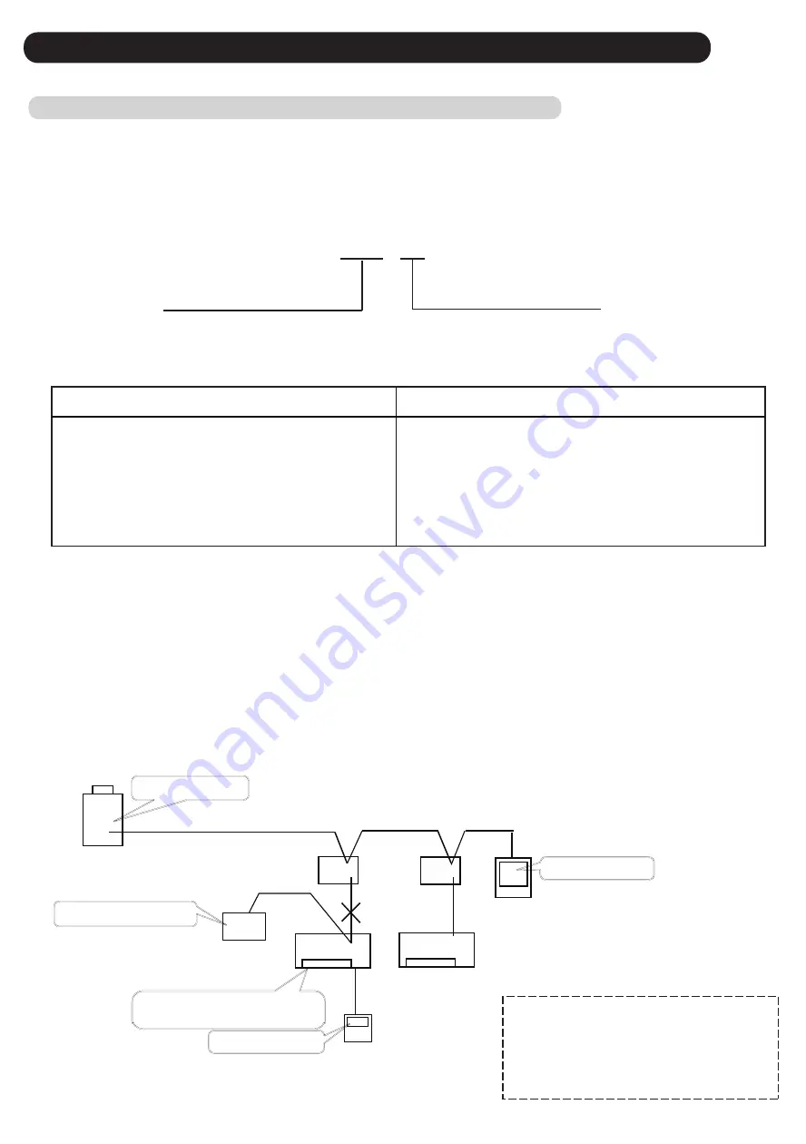
An Error code is represented by 3 digit characters.
The first 2 digit means the subsection Error code, and the last 1 digit means the specifics Error code.
Ex.) Indoor unit Network communication Error
Each Error code section is shown by the following target
Subsection Error Code target
Subsection and Specifics Error code target
When an Error occurs, each devices indicate own abnormal detecting condtion.
In order to confirm the actual error condition, the following procedure are required.
1) Confirm the Specific Error code on the Outdoor unit 7 segment display or the Service tool.
Ex.1.) When the wired remote controller shows " 9 U (Outdoor unit Error)".
Ex.2*.) When the wired remote controller shows " 4 2 (Indoor unit Heat-Ex Sensor Error)"
2) Confirm each Error code on each devices in case of Network communication Error.
Ex.) When the Network cable of indoor unit 00 disconnected during operating
.
Operation LED: 1 time blinking
Timer LED: 4 times blinking
Error code “ 14.2 ”
Error code "14" “16”
Error code “14.1 or 14.3”
"Network communication Error"
*Indoor unit detects the condition of Error code 14.3,
but it can only display the Subsection Error code.
Outdoor unit
Service
Tool
Touch-panel Controller
Indoor unit 00
Indoor unit 01
RB
unit
RB
unit
Error code “ 14 ”
" No communication between
indoor unit 00 "
"14.1": No communication between Outdoorunit and
Service tool.
"14.3": Communication Error on the Indoor unit.
Wired remote
controller
Note: About Service tool
- To change the connecting location of service tool
can be helpful for the trouble shooting.
- To check the system configuration, the Address
checker function can be helpful for trouble shooting.
*The Specific Error code can be indicated by service tool.
- DipSW 4-2:ON Default Setting -
Error indication pattern
"14": Error on the Outdoorunit (14.2)
"16": The Communication Error between Touch-
panel controller and Error indoor unit.
Error indication pattern
04-03
Summary of Contents for Airstage UTP-RU01AH
Page 1: ...SERVICE MANUAL 208 230V 60Hz ...
Page 5: ...1 TEST RUN ...
Page 6: ......
Page 34: ...2 OUTDOOR UNIT OPERATION CONTROL ...
Page 59: ...3 INDOOR UNIT OPERATION ...
Page 60: ......
Page 82: ......
Page 83: ...4 TROUBLE SHOOTING ...
Page 84: ......
Page 186: ...04 96 0 24 AOUA120 208 230 AOUA72 90 0 19 RED WHITE BLACK U V W ...
Page 208: ...5 APPENDING DATA UNIT ...
Page 209: ......
Page 215: ...CASSETTE TYPE MODELS AUUB18TLAV AUUB24TLAV AUUB30TLAV AUUB36TLAV 05 06 ...
Page 217: ...MEDIUM STATIC PRESSURE DUCT TYPE MODEL ARUM24TLAV 05 08 MODEL ARUM30TLAV ARUM36TLAV ...
Page 218: ...HIGH STATIC PRESSURE DUCT TYPE MODELS ARUH36TLAV ARUH48TLAV ARUH60TLAV 05 09 ...
Page 219: ...FLOOR CEILING TYPE MODELS ABUA12TLAV ABUA14TLAV ABUA18TLAV ABUA24TLAV 05 10 ...
Page 220: ...CEILING TYPE MODELS ABUA30TLAV ABUA36TLAV INDOOR UNITS INDOOR UNITS 05 11 ...
Page 221: ...WALL MOUNTED TYPE MODELS ASUA7TLAV ASUA9TLAV ASUA12TLAV ASUA14TLAV 05 12 ...
Page 222: ...MODELS ASUB18TLAV ASUB24TLAV 05 13 ...
Page 224: ...MODEL UTP RU01AH MODEL UTP RU01BH 5 2 3 RB Unit 05 15 ...
Page 225: ...MODEL UTP RU01CH 05 16 ...
Page 226: ...MODEL UTP RU04BH 05 17 ...
Page 227: ...MODELS AAUA48TLAV 5 2 4 Outdoor Air Unit 05 18 MODELS AAUA72TLAV ...
Page 228: ...MODELS AAUA96TLAV 05 19 ...
Page 230: ...6 DISASSEMBLY PROCESS ...
Page 245: ......


