


[BTU]
[BTU]
115
[rps]
Total capacity
[BTU]
[rps]
48
Total capacity
INV
INV
INV
Total capacity
[rps]
48
68
INV
INV
INV
20
20
20
2 times 115
3 times 115
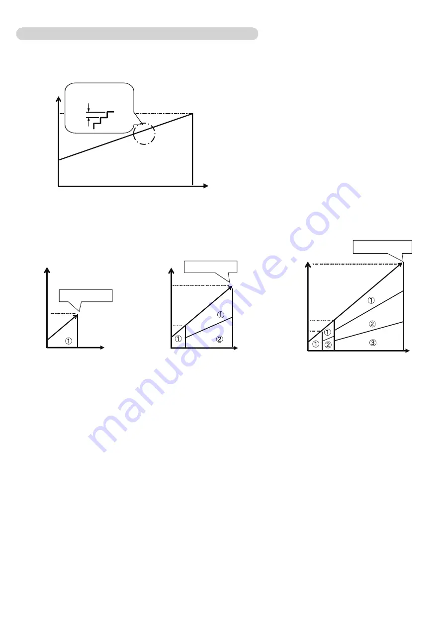
Stand-alone
2 Outdoor units
3 Outdoor units
20
115
Operating Range
(20 to 115 rps*)
Capacity
0.1 rps
on controlling steps1
On operating range: 20 to 115 rps*
[rps]
2-4-3 Capacity Control
(1) Capacity of compressor operation
By combining the operation of inverter compressors, the amount of required refrigerant circulation acceding to cooling and heating
load can be supplied from compressor efficiently.
The inverter compressor is able to control the amount of required refrigerant circulation in details.
(2) Target low-pressure and high-pressure control
In order to make the evaporation pressure of the indoor unit at the proper pressure on a variety of operations,
capacity of the compressor will be controlled by low-pressure sensor.
In order to make the condensation pressure of the indoor unit at the proper pressure on a variety of operations,
capacity of the compressor will be controlled by high-pressure sensor.
Target low-pressure and high pressure temperature depends on system capacity, capacity of compressor operation,
pipe length, and capacity shift switch settings.
<Cooling>
<Heating>
<Cooling main / Heating main>
In order to keep evaporation pressure / condensation pressure of the indoor unit at the proper pressure on a
variety of operations, capacity of the compressor and the capacity Heat exchange(incl. fan controll) will be
controlled by both of pressure sensor at the sametime
Ex) Combnation of 65cc compressor / Heating (Heating main)
*The maximum speed: 115 rps
Cooling (Cooling main) 100rps
Heating (Heating main) 115rps
02-05
Summary of Contents for Airstage UTP-RU01AH
Page 1: ...SERVICE MANUAL 208 230V 60Hz ...
Page 5: ...1 TEST RUN ...
Page 6: ......
Page 34: ...2 OUTDOOR UNIT OPERATION CONTROL ...
Page 59: ...3 INDOOR UNIT OPERATION ...
Page 60: ......
Page 82: ......
Page 83: ...4 TROUBLE SHOOTING ...
Page 84: ......
Page 186: ...04 96 0 24 AOUA120 208 230 AOUA72 90 0 19 RED WHITE BLACK U V W ...
Page 208: ...5 APPENDING DATA UNIT ...
Page 209: ......
Page 215: ...CASSETTE TYPE MODELS AUUB18TLAV AUUB24TLAV AUUB30TLAV AUUB36TLAV 05 06 ...
Page 217: ...MEDIUM STATIC PRESSURE DUCT TYPE MODEL ARUM24TLAV 05 08 MODEL ARUM30TLAV ARUM36TLAV ...
Page 218: ...HIGH STATIC PRESSURE DUCT TYPE MODELS ARUH36TLAV ARUH48TLAV ARUH60TLAV 05 09 ...
Page 219: ...FLOOR CEILING TYPE MODELS ABUA12TLAV ABUA14TLAV ABUA18TLAV ABUA24TLAV 05 10 ...
Page 220: ...CEILING TYPE MODELS ABUA30TLAV ABUA36TLAV INDOOR UNITS INDOOR UNITS 05 11 ...
Page 221: ...WALL MOUNTED TYPE MODELS ASUA7TLAV ASUA9TLAV ASUA12TLAV ASUA14TLAV 05 12 ...
Page 222: ...MODELS ASUB18TLAV ASUB24TLAV 05 13 ...
Page 224: ...MODEL UTP RU01AH MODEL UTP RU01BH 5 2 3 RB Unit 05 15 ...
Page 225: ...MODEL UTP RU01CH 05 16 ...
Page 226: ...MODEL UTP RU04BH 05 17 ...
Page 227: ...MODELS AAUA48TLAV 5 2 4 Outdoor Air Unit 05 18 MODELS AAUA72TLAV ...
Page 228: ...MODELS AAUA96TLAV 05 19 ...
Page 230: ...6 DISASSEMBLY PROCESS ...
Page 245: ......