


Trouble shooting 70 EJ1. 4
RB UNIT Error Method:
RB Unit transmission PCB2 parallel
communication Error
Indicate or Display:
Indoor Unit : 1st: Operation LED 13 times Flash, Timer LED 1 Times
Flash, Filter LED Continuous Flash.
2nd:Operation LED 1 time Flash, Timer LED 4 Times Flash
Outdoor Unit : E. 1 4.1 / 1 4.2*
Error Code : J 1 / 1 4
RB Unit : Power LED ON, Error LED Continuous Flash
Detective Actuators:
RB Unit Controller PCB Circuit
RB Unit Communication PCB
Detective details:
When Parallel Communication Error (Communication reset occurs continuously
more than specified times) is detected.
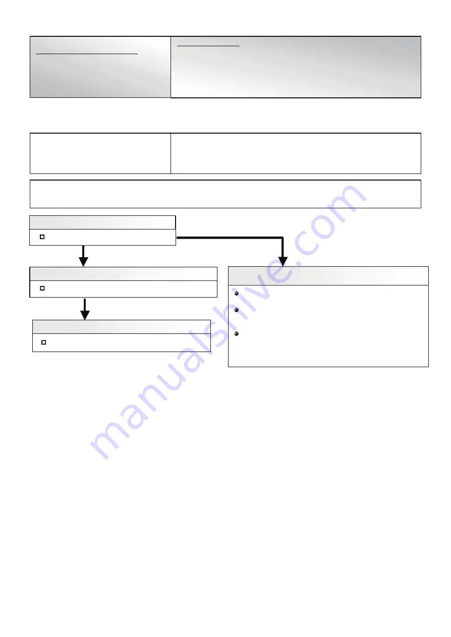
Check Point 3 : Replace Communication PCB
Forecast of Cause :
1. Connection failure 2. Outside cause 3. Communication PCB failure 4. Controller PCB defectve
Check Point 1 : Reset Power Supply
Does Error LED indication show again?
Replace Communication PCB.
Check Point 2 : Check RB Unit components
Check if RB Unit Communication PCB is removed.
Check Point 1-2 :
Check outside cause (Voltage drop or noise, etc.)
Instant drop ----- Check if there is a large load electric apparatus
in the same circuit.
Momentary power failure ----- Check if there is a defective
contact or leak current in the
power supply circuit.
Noise ----- Check if there is any equipment causing harmonic
wave near electric line (Neon bulb or electric
equipment that may cause harmonic wave).
Check the complete insulation of grounding.
NO
* Outdoor unit indicates 1 4.1 or 1 4.2 (No communication from Indoor unit)
Service tool indicates Error 1 4.3 or J 1.1, when the service tool detects No
communication of outdoor unit or the communication Error of RB unit.
04-79
Summary of Contents for Airstage UTP-RU01AH
Page 1: ...SERVICE MANUAL 208 230V 60Hz ...
Page 5: ...1 TEST RUN ...
Page 6: ......
Page 34: ...2 OUTDOOR UNIT OPERATION CONTROL ...
Page 59: ...3 INDOOR UNIT OPERATION ...
Page 60: ......
Page 82: ......
Page 83: ...4 TROUBLE SHOOTING ...
Page 84: ......
Page 186: ...04 96 0 24 AOUA120 208 230 AOUA72 90 0 19 RED WHITE BLACK U V W ...
Page 208: ...5 APPENDING DATA UNIT ...
Page 209: ......
Page 215: ...CASSETTE TYPE MODELS AUUB18TLAV AUUB24TLAV AUUB30TLAV AUUB36TLAV 05 06 ...
Page 217: ...MEDIUM STATIC PRESSURE DUCT TYPE MODEL ARUM24TLAV 05 08 MODEL ARUM30TLAV ARUM36TLAV ...
Page 218: ...HIGH STATIC PRESSURE DUCT TYPE MODELS ARUH36TLAV ARUH48TLAV ARUH60TLAV 05 09 ...
Page 219: ...FLOOR CEILING TYPE MODELS ABUA12TLAV ABUA14TLAV ABUA18TLAV ABUA24TLAV 05 10 ...
Page 220: ...CEILING TYPE MODELS ABUA30TLAV ABUA36TLAV INDOOR UNITS INDOOR UNITS 05 11 ...
Page 221: ...WALL MOUNTED TYPE MODELS ASUA7TLAV ASUA9TLAV ASUA12TLAV ASUA14TLAV 05 12 ...
Page 222: ...MODELS ASUB18TLAV ASUB24TLAV 05 13 ...
Page 224: ...MODEL UTP RU01AH MODEL UTP RU01BH 5 2 3 RB Unit 05 15 ...
Page 225: ...MODEL UTP RU01CH 05 16 ...
Page 226: ...MODEL UTP RU04BH 05 17 ...
Page 227: ...MODELS AAUA48TLAV 5 2 4 Outdoor Air Unit 05 18 MODELS AAUA72TLAV ...
Page 228: ...MODELS AAUA96TLAV 05 19 ...
Page 230: ...6 DISASSEMBLY PROCESS ...
Page 245: ......