33
3
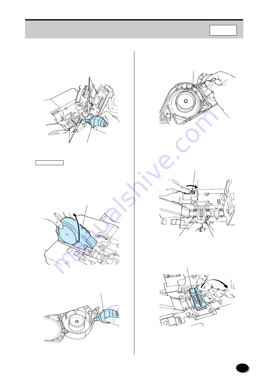
Blow off any dirt or dust adhering to the sensors
(glass surfaces) and film guide sections using
the blower brush.
IMPORTANT
• Take care not to scratch or mark the sensors.
Dirt or dust on the sensor or guide may scratch
or mark the films.
4
Remove the winding section.
5
Blow off any dirt or dust adhering to the inside.
6
Remove any dirt or dust adhering to the guide
rollers using a cotton swab.
7
While rotating the roller cleaning knob, use a
cotton swab moistened with magnet cleaner
(MC-100) to remove any dirt or dust adhering to
the rollers.
8
Remove the mask.
Sensors
Sensors
Blower Brush
EZ632
Winding Section
EZ1013
Blower Brush
EZ1014
Swab
EZ1324
Swab
Roller Cleaning Knob
Roller
EZ633
Mask
EZ1297
F350/370
distributed by www.minilablaser.com