COMMUNICATIONS
Modbus Communication
87
Modbus Communication
The VFD can be controlled and monitored through the Modbus RTU protocol over an RS-485 connection.
Modbus follows a simple client-server model. Server devices perform data read/write requests, which are
issued from a client device such as a Programmable Logic Controller (PLC) or Building Management System
(BMS). Assignable addresses for server devices range from an address of 1 to a theoretical maximum of 247.
As a server device, the VFD communicates all data using only 16-bit holding registers. Addressing for the
registers is partitioned into blocks that are multiples of 100 to group functionally similar data. If the drive is
configured to accept commands via remote communications, it can be commanded to start, stop, run at a
specified output frequency, target a setpoint in PID control, and reset faults.
Modbus addresses can be found in the parameter tables throughout this publication.
X-Drive Configuration for Modbus
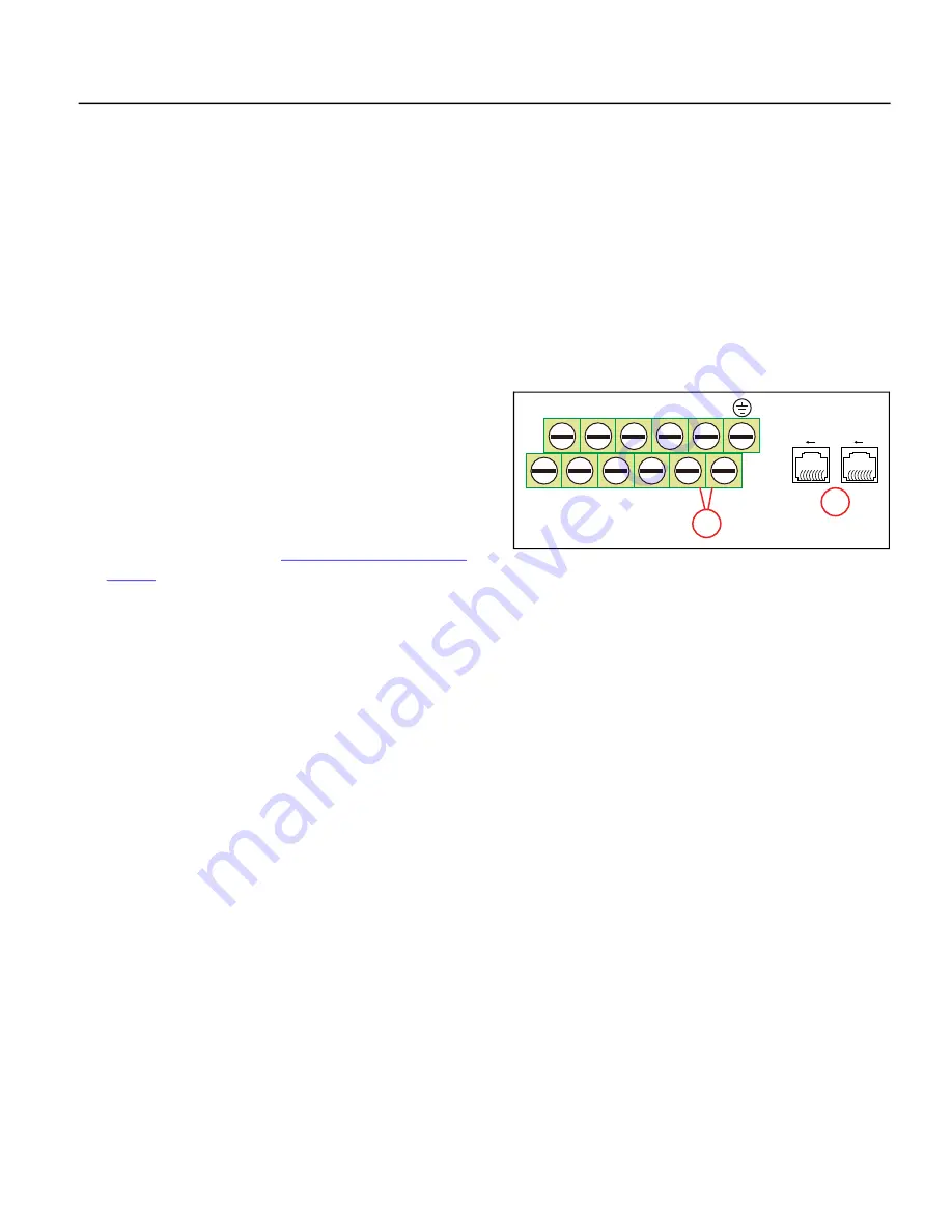
Use the X-Drive’s internal COM1 Port to connect to a Modbus net
-
work. COM1 can be accessed either through terminals SG+ and SG–
(1) or through one of the RJ45 connectors (2). RJ45 pins 4 and 5
are connected in parallel with SG+ and SG– and pins 3 and 6 are
parallel with SGND and Ground.
The X-Drive can also communicate with a Modbus network
through Ethernet, if an accessory Ethernet Communication card is
installed in the VFD. Refer to
To enable Modbus communications, set the following parameters:
Communication Parameters Setup
•
PLC Menu [SET–58]:
Use this setting to enable the PLC menu.
•
PLC Com Type [PLC–23]:
Set to
0_Modbus 485
. This enables Modbus on COM1 with the format
RTU 8, N, 1. When Modbus is enabled, BACnet communication, and PLC communication are disabled on
COM1.
•
COM1 Address [COMM–00]:
If the AC motor drive is controlled by RS-485 serial communication, the
communication address for this drive must be set via this parameter and each AC motor drive’s com
-
munication address must be different.
•
COM1 Speed [COMM–01]:
This parameter is for selecting the RS485 communication transmission
speed. Set 4.8K, 9.6K, 19.2K, 38.4K, 57.6K and 115.2K. If the value is not one of these 6 types, it will be
replaced by 9.6K.
•
COM1 Loss [COMM–02]:
Sets the action when communication errors occur.
•
COM1 Loss Delay [COMM–03]:
Setting for communication timeout detection.
•
COM1 Protocol [COMM–04]:
RS485 Protocol: Data Bits - Parity - Stop Bits - Message Format
•
Response Delay [COMM–05]:
Duration VFD waits before responding to received communication.
•
Main Frequency [COMM–06]:
When Auto Speed Ref [SET-07] is set to RS485 Interface, the last fre
-
quency command is stored in this parameter. After rebooting from an abnormal turn-off or momen
-
tary power loss, the VFD will continue operation with last frequency.
MI1
MI3
MI5
MI7
SGND
MI2
MI4
MI6
MI8
SG+
SG–
1
2
8 1
8 1
Summary of Contents for Cerus X-Drive
Page 2: ......
Page 3: ...CERUS X DRIVE INSTALLATION AND OPERATION MANUAL Firmware Version 1 1 Franklin Electric Co Inc ...
Page 94: ...COMMUNICATIONS BACnet Communication 94 ...
Page 98: ...ACCESSORIES Optional Extension Cards 98 Frame D Frame E Frame F ...
Page 99: ...ACCESSORIES Optional Extension Cards 99 Frame G Frame H ...


