


PHYSICAL INSTALLATION
Conduit Box Installation
23
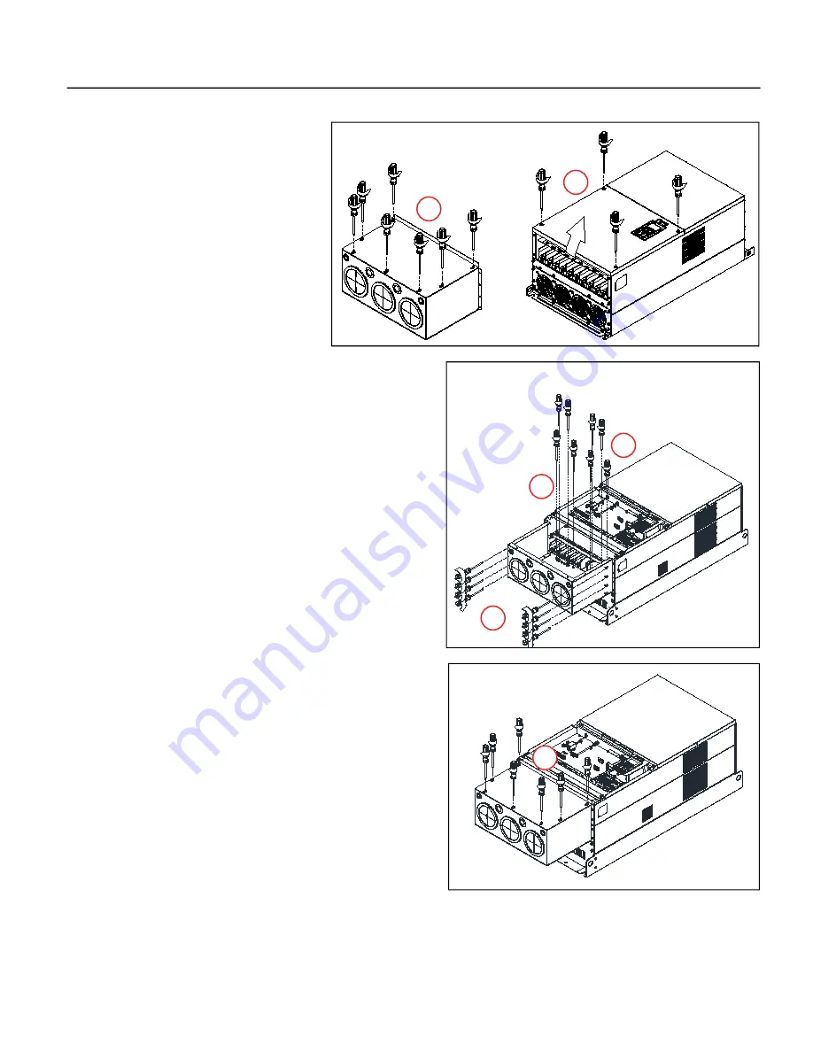
Frame G Conduit Box Installation
1.
Loosen seven conduit box cover screws,
slide it forward, and remove the cover.
2. Loosen four lower drive cover screws.
Remove the cover.
3. Remove the eight screws identified.
4. Align the conduit box with the flanges of the drive. Reinstall the
eight screws from step 3.
M5 Screw torque: 24-26 kg-cm / 20.8-22.6 Ib-in. / 2.4-2.5 Nm
M8 Screw torque: 100-120 kg-cm / 86.7-104.1 Ib-in. / 9.8-11.8 Nm
5. Secure further with eight screws.
M5 Screw torque: 24-26 kg-cm / 20.8-22.6 Ib-in. / 2.4-2.5 Nm
M8 Screw torque: 100-120 kg-cm / 86.7-104.1 Ib-in. / 9.8-11.8 Nm
6. Set the conduit box cover on the conduit box and slide it toward
the conduit knockouts. Tighten the screws to a torque of
24-26 kg-cm / 20.8-22.6 Ib-in. / 2.4-2.5 Nm.
7. Place the cover back on the drive, and tighten the screws to a
torque of 12-15 kg-cm / 10.4-13 Ib-in. / 1.2-1.5 Nm.
1
2
3
4
5
6
Summary of Contents for Cerus X-Drive
Page 2: ......
Page 3: ...CERUS X DRIVE INSTALLATION AND OPERATION MANUAL Firmware Version 1 1 Franklin Electric Co Inc ...
Page 94: ...COMMUNICATIONS BACnet Communication 94 ...
Page 98: ...ACCESSORIES Optional Extension Cards 98 Frame D Frame E Frame F ...
Page 99: ...ACCESSORIES Optional Extension Cards 99 Frame G Frame H ...


