Stop&Start system activated from button on roof panel (LED on);
driver seat belt buckled.
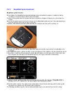
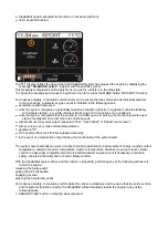
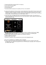
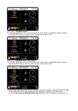
The TFT display notifies the driver when the Stop&Start system has stopped the engine by displaying the
message
"Stop&Start active"
, together with the specific symbol.
This message is displayed continuously for as long as the vehicle is in the stop state.
To cancel the message and reduce the symbol to icon form, press the MODE button ("ESCAPE" function).
For reasons of safety, to maintain comfort levels and to ensure that the vehicle and its individual systems
function correctly, automatic engine cut-out is inhibited in the following cases:
The system also constantly monitors a number of vehicle parameters (battery state of charge, engine coolant
temperature, catalytic converter temperature, clutch oil temperature, brake servo vacuum level, climate
comfort in passenger compartment) and will inhibit automatic engine cut-out if necessary to maintain
safety, vehicle functionality and on-board climate comfort.
accelerator pedal depressed;
when the system recognises a potentially hazardous situation (vehicle on a gradient, vehicle stationary
with wheels steered - e.g. while vehicle is about to turn into a junction or a roundabout);
when the system recognises that the vehicle is in a traffic queue or parking (by monitoring reverse gear
state, time elapsed since last stop and vehicle speed);
with maximum AC system output requested ("low", "max defrost" or "defrost rear screen");
with very low or very high external temperatures;
gearbox in "N";
DCT gearbox Park Lock function released manually;
in the event of a malfunction compromising the functionality of the system itself.
With the Stop&Start system active and the vehicle in stop state, performing any of the following actions will
restart the engine:
releasing the brake pedal;
pulling the UP shift paddle;
engaging reverse;
pressing the accelerator pedal.
For reasons of safety, to maintain comfort while the vehicle is stationary and to ensure that the entire vehicle
and its systems function correctly, the Stop&Start will automatically restart the engine in any of the
following cases:
ENGINE START button on steering wheel pressed;
Summary of Contents for California
Page 19: ...Z Tyre type and pressure label ...
Page 20: ...04 02 Assembly number Assembly number A Assembly number label ...
Page 21: ...04 03 Chassis number Chassis number B Punched chassis number ...
Page 22: ...04 04 Engine type and number Engine type and number C Punched engine type and number ...
Page 23: ...04 05 Chassis number Chassis number D Chassis number ...
Page 24: ...04 06 Gearbox type and number Gearbox type and number E Gearbox type and number plate ...
Page 25: ...04 07 Vehicle identification Vehicle identification K VIN label Vehicle Identification Number ...
Page 28: ...04 10 Fuel Fuel I Fuel label ...
Page 29: ...04 11 Paintwork Paintwork L Paintwork label ...
Page 30: ...04 12 Emissions control Emissions control M Emissions control data label ...
Page 31: ...04 13 Airbag Airbag N Do not install child seat on passenger seat label ...
Page 32: ...04 14 Airbag Airbag O Airbag maintenance label ...
Page 33: ...04 15 Airbag Airbag P Airbag warning label ...
Page 43: ...Fluids and lubricants table Model Fluids and lubricants table Download ...
Page 71: ...Screw the cap A back on tightly ...
Page 104: ...Connect the battery F2 01 ...
Page 118: ...Vehicle Setup Parameter Check Form Model Vehicle Setup Parameter Check Form Download ...
Page 520: ...A DCT gearbox clutch oil tank and clutch oil pump B Clutch oil pipes C Clutch oil radiator ...
Page 623: ...CCM Brake Disc Wear Form Model All Models CCM Brake Disc Wear Form Download ...
Page 1070: ...A Horn button B Engine start button C Manettino ...
Page 1102: ...Perform the respective cycle with the DEIS diagnostic tester ...
Page 1144: ...Connect the battery F2 01 ...
Page 1220: ...Precautions and guidelines for using the RHT retractable hard top ...
Page 1334: ...Undo the indicated fasteners Retrieve the indicated shims Release the clip 1 ...
Page 1335: ...Remove the indicated clip Undo the indicated screw Undo the screws indicated ...
Page 1452: ...Refit the rear wheelhouses E3 05 Connect the battery F2 01 ...
Page 1453: ...F2 07 Lights Diagnosing condensation in headlamps ...
Page 1561: ...Ss Sensor signal λ Lambda ratio excess g Rich mixture M Lean mixture ...
Page 1570: ...Refit the DCT gearbox C2 03 Connect the battery F2 01 ...
Page 1656: ...G Heater evaporator H Pollen filter I Air vents M Expansion valve ...
Page 1677: ...Refit the front wheelhouses E3 05 ...
Page 1686: ...Refit the caps 1 Refit the engine compartment cosmetic shields E3 13 ...

