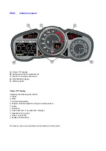
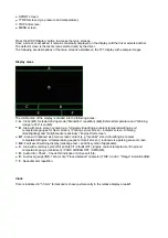

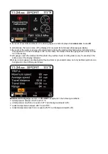
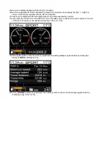
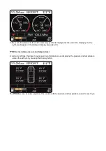

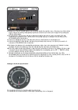
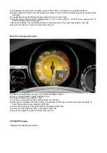


Via the specific option in the set-up menu, speedometer reading display may be disabled, enabling the
display of "
RANGE
" information only.
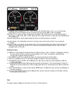
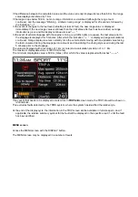
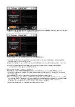
Resetting the trip odometer:
Reset the trip odometer with the TFT display control buttons.
In default screen conditions (MENU function not active), if TRIP B was disabled previously, pressing and
holding MODE directly resets the TRIP A count.
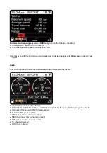
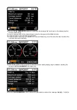
Conversely, if TRIP B was previously enabled, the value for either trip A or trip B starts to flash in area E2 of
the display, depending on which of the two was active in this area previously.
Press UP / DOWN to select between trip A and trip B, then press MODE to reset the selected trip value.
After pressing MODE, the parameter displayed previously in E2 is recalled (and updated, if following a reset).
With the trip A or trip B value flashing, to recall the parameter previously shown in area E2 without resetting
either of the TRIP values, do not press any buttons for 10 seconds.
Counter reset is not possible after key-off or with the key removed.
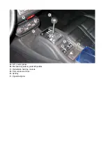
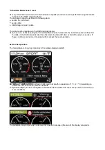
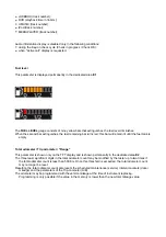
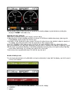
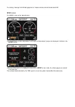
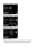
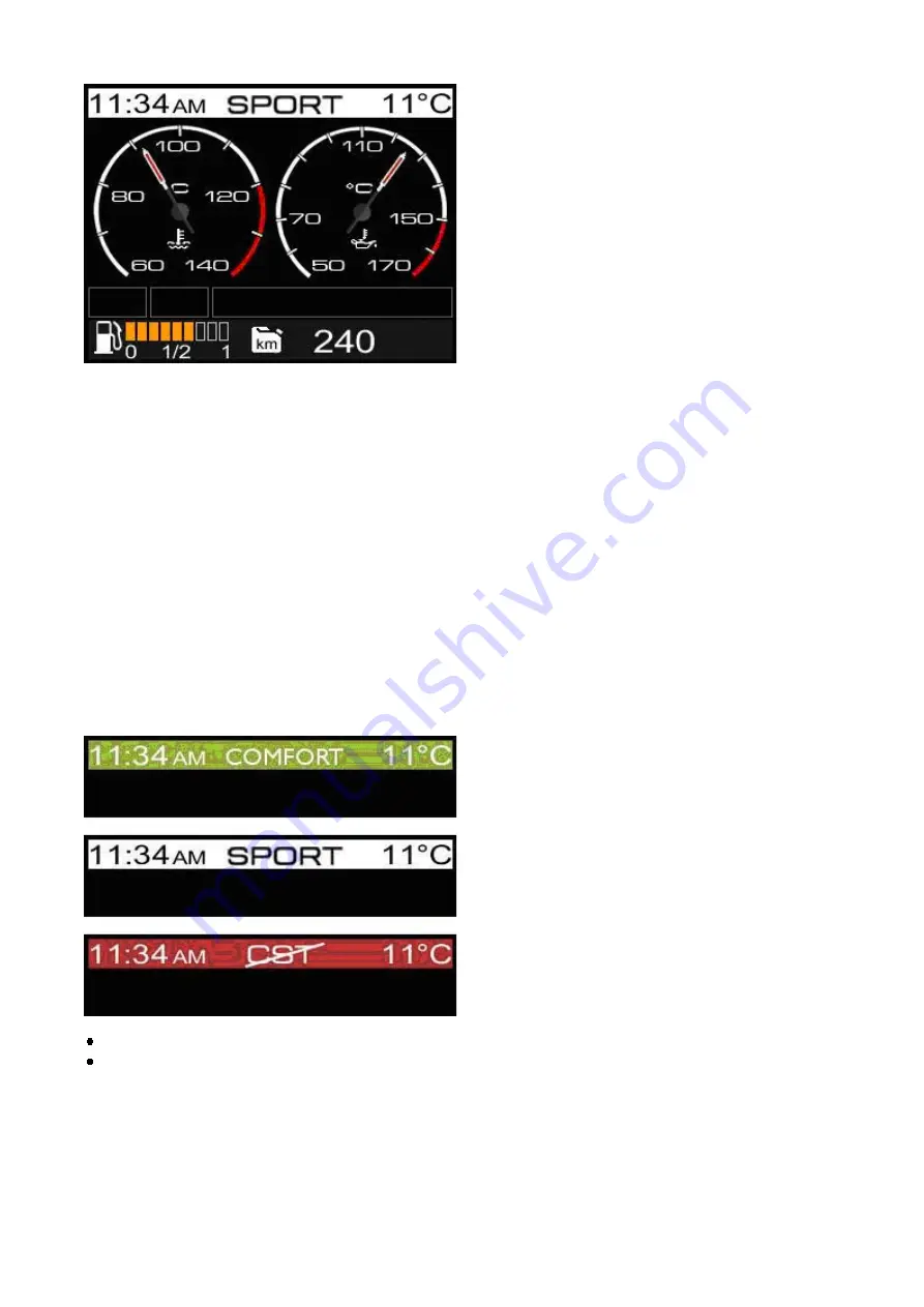
Selected driving mode
The driving mode selected via the Manettino is shown permanently in area
A
of the display, even in the event
of one or more faults.
The name of the
SELECTED DRIVING MODE
is shown on the display:
COMFORT;
SPORT;
Summary of Contents for California
Page 19: ...Z Tyre type and pressure label ...
Page 20: ...04 02 Assembly number Assembly number A Assembly number label ...
Page 21: ...04 03 Chassis number Chassis number B Punched chassis number ...
Page 22: ...04 04 Engine type and number Engine type and number C Punched engine type and number ...
Page 23: ...04 05 Chassis number Chassis number D Chassis number ...
Page 24: ...04 06 Gearbox type and number Gearbox type and number E Gearbox type and number plate ...
Page 25: ...04 07 Vehicle identification Vehicle identification K VIN label Vehicle Identification Number ...
Page 28: ...04 10 Fuel Fuel I Fuel label ...
Page 29: ...04 11 Paintwork Paintwork L Paintwork label ...
Page 30: ...04 12 Emissions control Emissions control M Emissions control data label ...
Page 31: ...04 13 Airbag Airbag N Do not install child seat on passenger seat label ...
Page 32: ...04 14 Airbag Airbag O Airbag maintenance label ...
Page 33: ...04 15 Airbag Airbag P Airbag warning label ...
Page 43: ...Fluids and lubricants table Model Fluids and lubricants table Download ...
Page 71: ...Screw the cap A back on tightly ...
Page 104: ...Connect the battery F2 01 ...
Page 118: ...Vehicle Setup Parameter Check Form Model Vehicle Setup Parameter Check Form Download ...
Page 520: ...A DCT gearbox clutch oil tank and clutch oil pump B Clutch oil pipes C Clutch oil radiator ...
Page 623: ...CCM Brake Disc Wear Form Model All Models CCM Brake Disc Wear Form Download ...
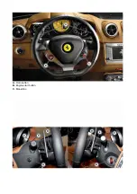
Page 1070: ...A Horn button B Engine start button C Manettino ...
Page 1102: ...Perform the respective cycle with the DEIS diagnostic tester ...
Page 1144: ...Connect the battery F2 01 ...
Page 1220: ...Precautions and guidelines for using the RHT retractable hard top ...
Page 1334: ...Undo the indicated fasteners Retrieve the indicated shims Release the clip 1 ...
Page 1335: ...Remove the indicated clip Undo the indicated screw Undo the screws indicated ...
Page 1452: ...Refit the rear wheelhouses E3 05 Connect the battery F2 01 ...
Page 1453: ...F2 07 Lights Diagnosing condensation in headlamps ...
Page 1561: ...Ss Sensor signal λ Lambda ratio excess g Rich mixture M Lean mixture ...
Page 1570: ...Refit the DCT gearbox C2 03 Connect the battery F2 01 ...
Page 1656: ...G Heater evaporator H Pollen filter I Air vents M Expansion valve ...
Page 1677: ...Refit the front wheelhouses E3 05 ...
Page 1686: ...Refit the caps 1 Refit the engine compartment cosmetic shields E3 13 ...


