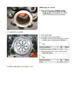


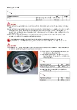

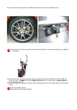

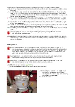
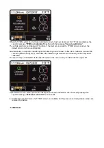

Place the wheel on the self-centring clamp and
use the bead breaker to ensure that the
wheel is gripped correctly by the clamps
(2)
on the table.
If the machine is not equipped with a bead
breaker, clamp the wheel from the inside.
Clamp the wheel.
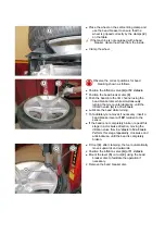
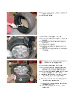
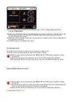
Observe the correct positions for bead
breaking shown as follows.
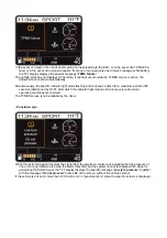
Position the inflation valve
(A)
at
12 o'clock
.
Position the bead breaker disc
(3)
.
Push the bead into the rim channel using the
bead breaker disc while simultaneously
turning the tyre counterclockwise, until the
inflation valve
(A)
is at
3 o'clock
.
Lubricate the bead while turning.
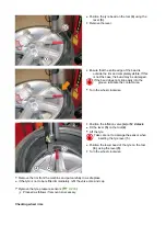
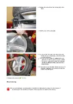
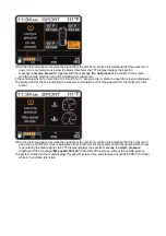
To facilitate tyre removal, if necessary, insert a
bead breaker lever at
180°
relative to the
sensor.
If the bead is not completely broken, repeat this
stage in a clockwise direction, moving the
inflation valve from
3 o'clock
to
12 o'clock
.
Perform this stage repeatedly, clockwise and
anticlockwise, until the bead is completely
broken.
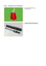
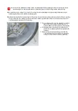
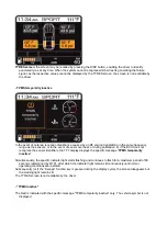
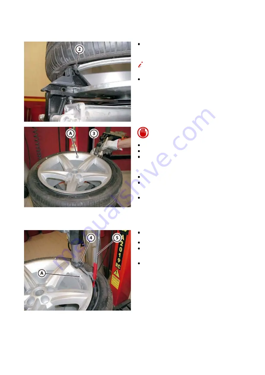
Fit tool
(4)
: after clamping, the tool automatically
moves upwards and outwards.
Position the inflation valve
(A)
at
11 o'clock
.
Mount the lever
(5)
on tool
(4)
, using the bead
breaker disc to facilitate the operation if
necessary.
Remove the bead breaker disc.
Summary of Contents for California
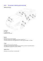
Page 19: ...Z Tyre type and pressure label ...
Page 20: ...04 02 Assembly number Assembly number A Assembly number label ...
Page 21: ...04 03 Chassis number Chassis number B Punched chassis number ...
Page 22: ...04 04 Engine type and number Engine type and number C Punched engine type and number ...
Page 23: ...04 05 Chassis number Chassis number D Chassis number ...
Page 24: ...04 06 Gearbox type and number Gearbox type and number E Gearbox type and number plate ...
Page 25: ...04 07 Vehicle identification Vehicle identification K VIN label Vehicle Identification Number ...
Page 28: ...04 10 Fuel Fuel I Fuel label ...
Page 29: ...04 11 Paintwork Paintwork L Paintwork label ...
Page 30: ...04 12 Emissions control Emissions control M Emissions control data label ...
Page 31: ...04 13 Airbag Airbag N Do not install child seat on passenger seat label ...
Page 32: ...04 14 Airbag Airbag O Airbag maintenance label ...
Page 33: ...04 15 Airbag Airbag P Airbag warning label ...
Page 43: ...Fluids and lubricants table Model Fluids and lubricants table Download ...
Page 71: ...Screw the cap A back on tightly ...
Page 104: ...Connect the battery F2 01 ...
Page 118: ...Vehicle Setup Parameter Check Form Model Vehicle Setup Parameter Check Form Download ...
Page 520: ...A DCT gearbox clutch oil tank and clutch oil pump B Clutch oil pipes C Clutch oil radiator ...
Page 623: ...CCM Brake Disc Wear Form Model All Models CCM Brake Disc Wear Form Download ...
Page 1070: ...A Horn button B Engine start button C Manettino ...
Page 1102: ...Perform the respective cycle with the DEIS diagnostic tester ...
Page 1144: ...Connect the battery F2 01 ...
Page 1220: ...Precautions and guidelines for using the RHT retractable hard top ...
Page 1334: ...Undo the indicated fasteners Retrieve the indicated shims Release the clip 1 ...
Page 1335: ...Remove the indicated clip Undo the indicated screw Undo the screws indicated ...
Page 1452: ...Refit the rear wheelhouses E3 05 Connect the battery F2 01 ...
Page 1453: ...F2 07 Lights Diagnosing condensation in headlamps ...
Page 1561: ...Ss Sensor signal λ Lambda ratio excess g Rich mixture M Lean mixture ...
Page 1570: ...Refit the DCT gearbox C2 03 Connect the battery F2 01 ...
Page 1656: ...G Heater evaporator H Pollen filter I Air vents M Expansion valve ...
Page 1677: ...Refit the front wheelhouses E3 05 ...
Page 1686: ...Refit the caps 1 Refit the engine compartment cosmetic shields E3 13 ...


