background image


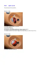
E5.08 Ignition 

switch 

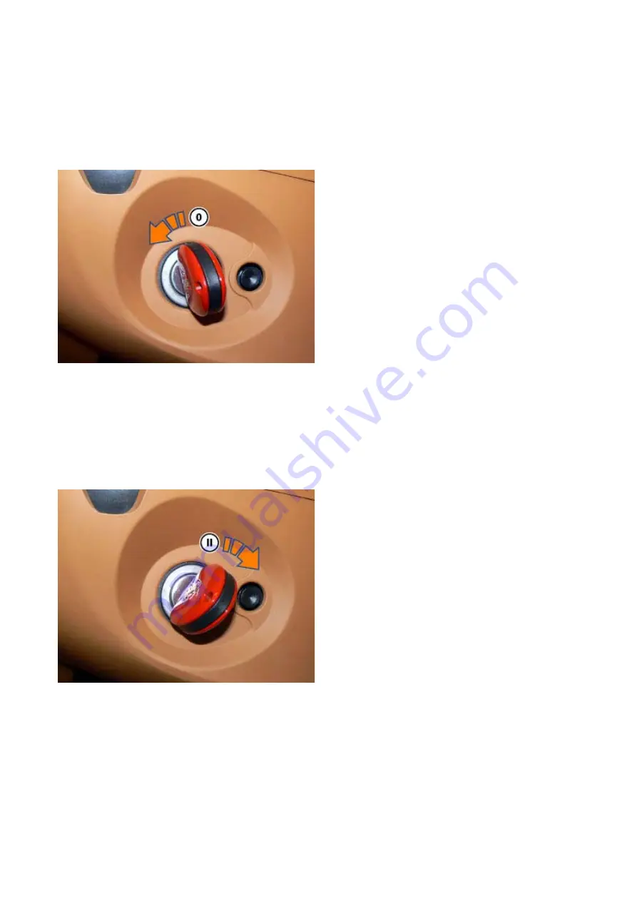
The ignition key has two positions: 

Position 0 - Stop 

Turn the key counterclockwise to position 

0

The engine switches off. 
The key may be removed. 
When the key is even partially extracted, the steering column is locked. 
The hazard warning lights and parking lights may be switched on. 
To facilitate releasing the steering lock, wiggle the steering wheel gently while turning the key. 

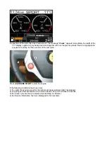
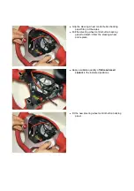
Position II - Start 

Turn the key clockwise to position 

II

Summary of Contents for California

Page 1: ... the accuracy of this Workshop Manual the manufacturer Ferrari shall not in any circumstances be held responsible for any inaccuracy or the consequences thereof The manufacturer Ferrari reserves the right to vary specifications without notice in accordance with its policy of continual product improvement Download workshop Manual as PDF ...

Page 2: ...r indicating the relative section the chapter number and a sequential number separated from the former by a point This format is used for all references to chapters or paragraphs in other sections The chapter or paragraph containing the notes relative to a certain topic may be identified by consulting the table of contents at the beginning of each section To illustrate the topic more clearly the t...

Page 3: ...will be updated periodically to reflect modifications made to the vehicle and the production of new versions ALWAYS read the Technical Notes as they may introduce more recently updated regulations and methods than those in this manual ...

Page 4: ...angerous and result in serious injury to the operator and or to persons in the vicinity IMPORTANT Failure to observe the instructions in this note may result in irreparable damage to the vehicle and or its parts ENVIRONMENTAL SAFETY This symbol indicates recommendations for environmental safety NOTE Indicates a note of a generic nature providing the operator with useful information concerning the ...

Page 5: ... bring it back within the prescribed tolerance range Right hand and or left hand The terms right hand and or left hand indicate the right hand and or left hand side of the vehicle with respect to the front of the vehicle ABS Anti Blockier System ABS prevents wheel lock up under braking to maintain directional control over the vehicle A C Air conditioning ASR Antriebs Schlupf Regelung Wheelspin con...

Page 6: ...tronically controlled differential integrated with the EF1 Trac traction control system EBD Electronic Brake Force Distribution Electronic brake force distribution system ECU Electronic Control Unit Electronic control unit EF1 TRAC Traction control integrated with Hy Kers system Excess torque produced by the engine is used by the Hy Kers system to charge the high voltage battery The system is self...

Page 7: ...age High voltage electrical system HVB High Voltage Battery 480 Volt high voltage battery situated under the passenger compartment which accumulates the energy necessary to power the Hy Kers hybrid system HPU Hybrid Power Unit Power unit of the Hy Kers hybrid system consisting of a DC DC inverter and converter LC Launch Control Performance start strategy LV Low Voltage Low voltage electrical syste...

Page 8: ...VDC Vehicle Dynamic Control Vehicle dynamics control using the brake system and engine torque 4WD 4 Wheel Drive 4 wheel drive system ...

Page 9: ...ork on FERRARI cars This manual is intended for expert operators with sufficient knowledge and skill to carry out all maintenance and repair operations for FERRARI cars correctly and safely Carrying out the aforementioned operations without the necessary knowledge and skills will cause damage to the vehicle and may expose the operator and the user of the vehicle to danger ...

Page 10: ... manual contains diagnostic procedures to identify malfunctions of the different components in the vehicle Evaluating the impressions of the user is of vital importance formulating appropriate questions to clearly identify the symptoms of the problem Once the cause has been identified plan the job by consulting the relative informative notes concerning the tools necessary the reference data for se...

Page 11: ... out correctly and safely Carrying out any work without using specific FERRARI tools or using alternative tools may cause damage to relative component and or system voiding the warranty Always use original FERRARI spare parts consulting the relative spare parts catalogue In addition to voiding the warranty using non original components may damage the vehicle and expose the user to danger ...

Page 12: ...pecific FERRARI tools or using alternative tools may cause damage to relative component and or system voiding the warranty Always use original FERRARI spare parts consulting the relative spare parts catalogue In addition to voiding the warranty using non original components may damage the vehicle and expose the user to danger During this period the appropriate form must be filled out and the S T S...

Page 13: ...onents Ferrari has defined three tolerance classes relative to the rated torque value The tolerance class is shown in the summary paragraphs concerning tightening torques at the beginning of each section and or at the beginning of each paragraph A 5 B 10 C 20 Class ...

Page 14: ... and wear the appropriate personal protective equipment The personal protective equipment used must comply with applicable safety legislation and must be in excellent condition Footwear Wear safety footwear at all times Gloves Wear safety gloves when working with or near sharp or hot objects and when handling liquids that are harmful to the skin Eyewear ...

Page 15: ...Wear safety eyewear when working underneath the vehicle and when handling liquids that are harmful for the eyes Ear plugs Use safety ear plugs when working with the engine running ...

Page 16: ... Petrol Danger Precautions Prolonged skin contact with used oil may cause severe skin disease Keep out of reach of children To prevent risks always wear protective gloves and or wash any areas that have come into contact with used oil thoroughly with soap and water Never dispose of used oil into the environment Used oil Danger Precautions The fluid contained in the brake clutch and power steering ...

Page 17: ... remove any of their internal elements Never use the vehicle with any of these devices removed Each of these devices bears a marking or label indicating the type approval number obtained Never replace any of the original devices with devices without type approval These devices must also be kept in proper working order carrying out all the procedures indicated in the maintenance schedule Exhaust ga...

Page 18: ...Number L Paintwork label M Emissions control data label N Do not install child seat on passenger seat label O Airbag maintenance label P Airbag warning label R Label with instructions for placing luggage in luggage compartment S Labels with instructions for placing luggage in luggage compartment T Engine oil gear oil and hydraulic clutch system fluid type label U Engine oil level check label V Rad...

Page 19: ...Z Tyre type and pressure label ...

Page 20: ...04 02 Assembly number Assembly number A Assembly number label ...

Page 21: ...04 03 Chassis number Chassis number B Punched chassis number ...

Page 22: ...04 04 Engine type and number Engine type and number C Punched engine type and number ...

Page 23: ...04 05 Chassis number Chassis number D Chassis number ...

Page 24: ...04 06 Gearbox type and number Gearbox type and number E Gearbox type and number plate ...

Page 25: ...04 07 Vehicle identification Vehicle identification K VIN label Vehicle Identification Number ...

Page 26: ...04 08 Tyres Tyres F Tyre pressure monitoring system identifier label Z Tyre type and pressure label ...

Page 27: ...04 09 Antifreeze and expansion tank opening instructions Antifreeze and expansion tank opening instructions G Antifreeze label H Expansion tank opening instructions label ...

Page 28: ...04 10 Fuel Fuel I Fuel label ...

Page 29: ...04 11 Paintwork Paintwork L Paintwork label ...

Page 30: ...04 12 Emissions control Emissions control M Emissions control data label ...

Page 31: ...04 13 Airbag Airbag N Do not install child seat on passenger seat label ...

Page 32: ...04 14 Airbag Airbag O Airbag maintenance label ...

Page 33: ...04 15 Airbag Airbag P Airbag warning label ...

Page 34: ...04 16 Luggage placement in luggage compartment Luggage placement in luggage compartment R Label with instructions for placing luggage in luggage compartment ...

Page 35: ...04 17 Luggage placement in luggage compartment Luggage placement in luggage compartment S Labels with instructions for placing luggage in luggage compartment ...

Page 36: ...04 18 Engine oil gear oil and hydraulic clutch system fluid Engine oil gear oil and hydraulic clutch system fluid T Engine oil gear oil and hydraulic clutch system fluid type label ...

Page 37: ...04 19 Engine oil level check and radiator with antifreeze Engine oil level check and radiator with antifreeze U Engine oil level check label V Radiator with antifreeze label ...

Page 38: ...04 20 Safety standard compliance and mercury warning label Safety standard compliance and mercury warning label X Mercury warning label Y Safety standard compliance label ...

Page 39: ...04 21 Stop Start system warning label optional Stop Start system warning label optional W Stop Start system warning labels optional ...

Page 40: ...and consumption Performance DCT gearbox 3 9 sec 193 mph Mechanical gearbox 4 2 sec 193 mph 0 to 62 mph Top speed Consumption for vehicles with DCT gearbox Urban cycle 13 mpg Extraurban cycle 19 mpg Combined cycle 15 mpg ...

Page 41: ...sions and weights Wheelbase 105 12 in Max length 179 6 in Max width 75 15 in Max height 52 04 in Front overhang 37 4 in Rear overhang 37 in Front track 64 17 in Rear track 63 18 in Kerb weight DCT 3925 lb Kerb weight mechanical gearbox ...

Page 42: ...tective fluid with antifreeze action for monoethylene glycol based cooling systems 50 Water 50 Cooling circuit 1 Mixture of water and denatured isopropyl alcohol 50 Glass cleaner 2 phial Windscreen washer headlight washer system ...

Page 43: ...Fluids and lubricants table Model Fluids and lubricants table Download ...

Page 44: ...an 40 000 km 25 000 miles Download Scheduled maintenance plan 60 000 km 37 500 miles Download Scheduled maintenance plan 80 000 km 50 000 miles Download Scheduled maintenance plan 100 000 km 62 500 miles Download Scheduled maintenance plan 120 000 km 75 000 miles Download Scheduled maintenance plan 140 000 km 87 500 miles Download Scheduled maintenance plan 160 000 km 100 000 miles Download ...

Page 45: ...engine oil level the vehicle must be on a level surface and the engine must be warm Start the engine Wait for the engine oil temperature to reach 80 to 90 C IMPORTANT Only check the engine oil level with the ENGINE OFF Switch off the engine Open the engine compartment lid Remove the dipstick A Undo and remove the cap B Wait 5 minutes to allow the oil to return to the sump ...

Page 46: ...type specified in the fluids and lubricants table If the engine oil level is near or below the MIN limit top the system up to between the MIN and MAX limits with new engine oil of the specified type Fit and tighten the cap B securely After topping up the engine oil the TFT display may continue to display the relative icon with the specific message Check engine oil level for a prolonged period of t...

Page 47: ...speed 720 rpm for 2 minutes IMPORTANT Only check the engine oil level with the ENGINE OFF Switch off the engine Open the engine compartment lid Undo and remove the cap B Wait 5 minutes to allow the engine oil to return to the sump Clean the dipstick A Insert the dipstick A fully Remove the dipstick A ...

Page 48: ...he engine oil level is near or below the MIN limit top the system up to between the MIN and MAX limits with new engine oil of the specified type Fit and tighten the cap B securely After topping up the engine oil the TFT display may continue to display the relative icon with the specific message Check engine oil level for a prolonged period of time This is completely normal Draining the engine lubr...

Page 49: ...ust be replaced at every oil change The engine oil filter is located on the right hand side of the engine Remove the central flat undertray section E3 12 Drain the engine lubrication system A3 01 Fit the tool 95971560 on the filter A using the wrench USAG D156 Turning counterclockwise as indicated by the arrow unscrew the engine oil filter A Remove the filter between the front removable subframe a...

Page 50: ...e mating surface on the lower crankcase shell Use filter cartridges recommended by Ferrari only and check that the rubber seal of the filter cartridge fits perfectly into the seat with the round part visible and that there are no cuts and or cracks Lubricate the rubber seal of the filter cartridge with a film of engine oil Fit the new oil filter cartridge A rotating it clockwise using the tool 959...

Page 51: ...Gradually add new oil of the specified type via the filler neck Due to inevitable pooling within the lubrication system the actual quantity of oil added may vary from vehicle to vehicle Fully tighten the engine oil filler cap B Check the engine oil level A3 01 Check that there are no leaks from the drain plug and engine oil filter Refit the central flat undertray section E3 12 Filling the engine l...

Page 52: ... system the actual quantity of oil added may vary from vehicle to vehicle After draining the oil from the relative drain plug orifice for approximately 20 minutes and replacing the filter when the system is filled with approximately the aforementioned quantity the oil level will still be only halfway up the dipstick due to residual oil remaining in the sump After an initial oil level check adding ...

Page 53: ...el correctly carry out the following procedures precisely as described Remove the rear flat undertray diffuser E3 12 Ensure that the vehicle is NOT on a gradient Start the engine and run at idle speed Select reverse R and hold the brake pedal Check that the clutch system ATF fluid temperature DOES NOT exceed 40 C Check that the engine coolant temperature is between 40 and 50 C CAUTION HOT OIL may ...

Page 54: ...t undertray diffuser E3 12 Check level of Shell Transaxle 75W 90 GL5 gear oil ONLY for vehicles WITH single oil heat exchanger Gear oil drain filler plug GL differential Plug 25 Nm B Tightening torque Nm Class The following procedures must be carried out exactly as described to ensure that the hydraulics are proper lubricated and function correctly To check the gear oil level correctly carry out t...

Page 55: ...ocated on the rear surface of the transmission and check the level the fluid must reach the edge of the hole from which the plug was removed on the limit of overflowing If the level is too low identify the cause of excessive oil consumption If topping up is necessary proceed as follows Using the pump AV 8174 element 01 with the short spout adapted as previously described aspirate the specified oil...

Page 56: ...ugs indicated in the figure to collect the oil Undo the plugs 1 and 2 at the bottom of the gearbox housing ALWAYS dispose of liquids correctly in accordance with applicable legislation Collect all liquids drained from the vehicle systems in appropriate airtight containers then close the containers Drain the oil completely ONLY for vehicles WITHOUT single oil heat exchanger Remove the gear oil pipe...

Page 57: ...mpletely Filling the system with Shell Transaxle 75W 90 GL5 gear oil ONLY for vehicles WITHOUT single oil heat exchanger ATF and GL oil pipe mounting bracket Screw 20 Nm B Gear oil drain filler plug GL differential Plug 25 Nm B Tightening torque Nm Class Clean the unions to be connected thoroughly with a suitable degreaser that does not leave residue Connect the gear oil pipe unions Follow the ins...

Page 58: ...h 4 9 litres 2 9 litres approx 2 litres for external cooling circuit of oil via the level check filler hole Fill with half of the quantity indicated wait a few minutes for the fluid to settle then gradually finish filling until oil overflows from the check filler hole The quantity of oil required may vary slightly relevant to the amount indicated for filling the tank when empty this is due to unav...

Page 59: ...he plugs 1 and 2 Tightening torque Nm Class Plug 25 Nm B Using the pump AV 8174 element 01 with the short spout adapted as previously described aspirate the specified oil from a newly opened container Using the pump AV 8174 element 01 and a container for collecting excess oil fill with 3 5 litres via the level check filler hole with the piece of hose 3 Fill with half of the quantity indicated wait...

Page 60: ...f the gears Remove the rear flat undertray section E3 12 Remove the shield 1 fastening the EPB cable 2 undoing the indicated screws Remove the mounting bracket 3 undoing the indicated screws CONDITIONS FOR CHECKING LEVEL CORRECTLY To check the gear oil level correctly carry out the following procedures precisely as described 1 The vehicle must be on the vehicle lift with the engine running at idle...

Page 61: ...sive oil consumption If topping up is necessary no fluid flowed out of hole when plug was removed proceed as follows Use a pump to aspirate the specified oil from a new container Using the pump and a container for collecting excess oil top up via the level pipe until excess oil overflows from the orifice of the cap removed previously Let the oil fluid completely until the flow stops The level is c...

Page 62: ... flat undertray section E3 12 Place a container under the plug indicated in the figure to collect the oil Undo the plug 1 located at the bottom of the gearbox housing ALWAYS dispose of liquids correctly in accordance with applicable legislation Collect all liquids drained from the vehicle systems in appropriate airtight containers then close the containers Drain the oil completely Remove the gear ...

Page 63: ...ecessary blow compressed air into the pipes to speed up and facilitate drainage Place a container under the oil filter 6 Undo the screw fastening the oil filter 6 Remove the O ring on the filter and clean the oil filter 6 immersing in degreasing solution Take care not to damage the mesh Dry the oil filter 6 with compressed air Filling gear oil system with mechanical gearbox Fastening mechanical ge...

Page 64: ... leave residue Connect the gear oil pipe unions Follow the instructions given below to ensure proper connection ensure that the notch on the safety ring nut 14 is aligned with the pin 13 connect the male union and turn the safety ring nut 14 so that it is no longer aligned with the pin 13 ALWAYS ensure that the pipe union is effectively connected Connect the unions 5 for the gearbox oil pipes and ...

Page 65: ...ve seal Use a pump to aspirate the specified oil from a new container Using the pump fill with a total of 4 6 litres gearbox external cooling circuit via the speed sensor orifice Refit the plug 7 for the gearbox speed sensor seat replacing the relative seal and tightening the indicated screw Tightening torque Nm Class Screw 5 Nm C Check that there is no leakage from the drain plug the filter and t...

Page 66: ...ve the rear flat undertray section E3 12 Ensure that the vehicle is NOT on a gradient Start the engine and run at idle speed Select neutral N Alternatively select reverse R Wait for the ATF fluid temperature to reach approximately 60 C Ensure that the ATF fluid temperature does NOT exceed 80 C at any point during the operation Check that the engine coolant temperature is between 40 and 50 C CAUTIO...

Page 67: ...verflowing top up as follows Using the pump AV 8174 element 02 with the long spout aspirate the specified oil from a newly opened container Using the pump AV 8174 with attachment 02 and a container for collecting excess oil top up via the level pipe until excess oil overflows Let the oil fluid completely until the flow stops Replace and tighten the threaded plug 1 Tightening torque Nm Class Plug 2...

Page 68: ...dlight washer fluid tank is accessible by lifting the engine compartment lid Refill the tank until fluid is visible from the filler neck Low fluid level is detected by the sensor fitted on the tank and is indicated by the relevant instrument panel warning light In the event of windscreen washer or headlight washer system malfunction check the pumps on the tank ...

Page 69: ...f skin contact with fluid wash the respective part of the body immediately with plenty of water In the event of contact between the fluid and painted parts of the vehicle wash and dry the respective areas immediately Check that the fluid in the tank is always near the MAX level A low fluid level may be an indication of excessive oil consumption If the level is low remove the cap 1 and top up Top u...

Page 70: ... fluid level must be checked with the system warm after driving for at least 15 Km If checked cold the level may appear to be excessively low even with the correct amount of fluid in the system At the intervals specified in the MAINTENANCE SCHEDULE check the level of liquid in the power steering system Undo the cap A Use the dipstick on the cap A to check that the power steering fluid level is bet...

Page 71: ...Screw the cap A back on tightly ...

Page 72: ...new coolant has been introduced FROM Assembly No 87849 Carefully check which type of coolant has been used in the vehicle before topping up or filling the system Do not mix different types of coolant as this may alter their properties If not unscrew the cap A and top up to the correct level with the specified fluid Fully tighten the filler cap A onto the expansion tank Refit the engine compartment...

Page 73: ...ing the cooling system After loosening or removal the Caillau Visa hose clamps must be replaced with Mikalor worm drive hose clamps following the instructions given in Technical Information 2054 of December 2012 CAUTION The fluid in the engine coolant system may be very hot Hot engine coolant may cause severe burns ALWAYS WAIT FOR THE SYSTEM TO COOL BEFORE STARTING ANY WORK Check that all the conn...

Page 74: ...height of the header tank union The photo aside was taken with the secondary air pump removed to illustrate the procedure more clearly 02 Undo the union 2 on the delivery pipe 3 leading to the heat exchanger retrieving the relative seals 03 Unscrew the indicated right hand cylinder head bleed plug located on the front cover ...

Page 75: ...7849 Carefully check which type of coolant has been used in the vehicle before topping up or filling the system Do not mix different types of coolant as this may alter their properties 06 Gradually introduce coolant via the expansion tank filler orifice until fluid escapes from the open bleed orifice on the radiator 07 Reconnect the radiator bleed pipe 1 fastening with the indicated clamp ...

Page 76: ... plug 30 Nm B 10 Tighten the left hand bleed plug indicated after replacing the relative seal Tightening torque Nm Class M12x1 25x12 plug 30 Nm B 11 Gradually introduce coolant via the expansion tank filler orifice until fluid escapes from the delivery pipe 3 leading to the heat exchanger 12 Fasten the delivery pipe 3 leading to the heat exchanger by tightening the union 2 after replacing the rela...

Page 77: ...ing the maximum temperature for one zone only of the air conditioning system 20 Bring the engine speed to 2000 rpm for approximately 1 minute then run at idle speed for 30 seconds 21 Invert the temperature settings for the two air conditioning system zones TGK valve_2 open and TGK valve_1 closed 22 Bring the engine speed to 2000 rpm for approximately 1 minute then run at idle speed for 30 seconds ...

Page 78: ...28 Tighten the filler cap 4 completely onto the expansion tank Refit the front wheelhouses E3 05 Refit the engine compartment cosmetic shields E3 13 ...

Page 79: ...e right hand rear wheel bay Remove the rear wheelhouses E3 05 Remove the right one Remove the rear bumper E3 04 Remove the active carbon filter cover 1 by undoing the screws 2 Remove the fuel filler flap emergency release cable 3 from the relative cable grommet Remove the clamp 4 and detach the pipe 5 from the OBD pump filter Undo the screw 6 fastening the active carbon filter mounting bracket ...

Page 80: ... the pipe connecting the filter to the chassis Open the clamp 8 and release the pipe 6 connecting to the OBD pump filter Working via the aperture in the wheel bay disconnect the quick coupling 15 from the active carbon filter A ...

Page 81: ... both sides push the safety clip out of its seat until you hear the unclick The difference between the safety clip clicked and unclicked position is only a few millimetres Then press on both sides of the quick coupling and remove the pipe Working from the wheel bay undo the screw 10 fastening the active carbon filter mounting bracket Remove the active carbon filter complete with bracket and filter...

Page 82: ...ck The difference between the safety clip clicked and unclicked position is only a few millimetres Then press on both sides of the quick coupling and remove the lower pipe 17 Undo the screw 11 release the retainer bracket 12 detach the active carbon filter A and replace Refitting the active carbon filter Active carbon filter locking bracket chassis fastener bracket Screw 5 Nm B Fastening active ca...

Page 83: ...m Class Screw 5 Nm B Connect the pipes 17 to the active carbon filter as originally fitted A double lock safety clip is fitted on the lower pipe connected to the active carbon filter After connecting the quick connector fuel pipe correctly with due caution and pressing on both sides of the double lock clip push the clip into its seat until it clicks audibly into place and the pipe is secured corre...

Page 84: ...tightening the screw 10 Tightening torque Nm Class Screw 24 Nm B Connect the pipe 14 to the fuel vapour separator 16 A double lock safety clip is fitted on the pipe After connecting the quick connector fuel pipe correctly with due caution and pressing on both sides of the double lock clip push the clip into its seat until it clicks audibly into place and the pipe is secured correctly The differenc...

Page 85: ...l bay connect the quick coupling 15 to the active carbon filter A Fasten the rear of the active carbon filter by tightening the screw 6 Tightening torque Nm Class Screw 24 Nm B Connect the pipe 5 to the OBD pump filter and tighten the clamp 4 Fit the fuel filler flap emergency release cable 3 into the relative cable grommet ...

Page 86: ...ump filter as originally mounted closing the clamp 8 Fit the active carbon filter cover 1 and fasten by tightening the screws 2 The two lower screws also fasten the heat shield mounting bracket onto the silencer Tightening torque Nm Class Screw 6 Nm B Refit the rear bumper E3 04 Refit the rear wheelhouses E3 05 ...

Page 87: ...nt of the left catalytic converter Disconnect the battery F2 01 Remove the central flat undertray section E3 12 Remove the front wheelhouses E3 05 Remove the left one Detach the connector 1 Detach the cable from the clamp 2 Undo the front oxygen sensor A from the catalytic converter and replace Fit the front oxygen sensor A onto the catalytic converter and tighten it Tightening torque Nm Class Oxy...

Page 88: ... specific product Whenever a sensor is replaced the self acquired parameters must be deleted from the ECU memory Located at the rear of the left catalytic converter Disconnect the battery F2 01 Remove the central flat undertray section E3 12 Remove the front wheelhouses E3 05 Remove the left one Detach the connector 1 Cut the plastic clamp indicated Detach the cable from the clamp 2 Detach the cab...

Page 89: ...en it Tightening torque Nm Class Oxygen sensor 50 Nm B Attach the cable to the clamp 3 Attach the cable to the clamp 2 Fit a new plastic clamp in the position indicated Connect the connector 1 Refit the front wheelhouses E3 05 Refit the central flat undertray section E3 12 Connect the battery F2 01 Replacing the front right oxygen sensor ...

Page 90: ...the right one Detach the connector 1 Detach the cable from the clamp 2 Undo the front oxygen sensor C from the catalytic converter and replace Fit the front oxygen sensor C onto the catalytic converter and tighten it Tightening torque Nm Class Oxygen sensor 50 Nm B Attach the cable using the clamp 2 Connect the connector 1 Refit the front wheelhouses E3 05 Refit the central flat undertray section ...

Page 91: ...lat undertray section E3 12 Remove the front wheelhouses E3 05 Remove the right one Detach the connector 1 Detach the cable from the clamp 2 Detach the cable from the clamp 3 Undo the rear oxygen sensor D from the catalytic converter and replace Fit the rear oxygen sensor D onto the catalytic converter and tighten it Tightening torque Nm Class Oxygen sensor 50 Nm B Attach the cable to the clamp 3 ...

Page 92: ...Attach the cable to the clamp 2 Connect the connector 1 Refit the front wheelhouses E3 05 Refit the central flat undertray section E3 12 Connect the battery F2 01 ...

Page 93: ...le There are two located in the engine compartment behind the front bumper The instructions above are for the left hand filter Use the same procedure for the right hand filter Remove the engine compartment cosmetic shields E3 13 Remove the front cosmetic shield and the left hand lateral cosmetic shield Remove the clamp 1 fastening the air box cover 2 to the bellow Undo the six screws indicated and...

Page 94: ...rfaces with the air box The following components must ONLY be replaced in the event of evident damage Fit the filter 4 in its seat as originally installed Fit the grille 3 in its seat as originally installed Fit the air box cover 2 and fasten by hand tightening the six screws indicated Refit and tighten the clamp 1 fastening the air box cover 2 to the bellow Refit the engine compartment cosmetic s...

Page 95: ...changed regularly The air conditioning and heating system filter is located inside the passenger compartment on the right hand side of the heater evaporator It is accessible from beneath the passenger side of the dashboard Replace the air conditioning and heating system air filter at the intervals indicated in the MAINTENANCE SCHEDULE Remove the passenger side underdashboard trim panel E4 02 Move ...

Page 96: ...the filter in the correct direction using the arrow indicating the direction of air flow AIR FLOW as reference Fit the cover 2 Move the bracket 1 in the direction indicated by the arrow Refit the passenger side underdashboard trim panel E4 02 ...

Page 97: ...belt but without touching the belt itself Tap the belt with a suitable tool near the tension probe and check that the value read by the meter is between 115 and 177 Hz Replace the belt if the frequency measured is lower than the specified value Checking the tension of the A C compressor power steering pump alternator drive belt Fastening belt tensioner to crankcase Screw 25 Nm B Tightening torque ...

Page 98: ...replaced recently replace the belt tensioner as described below Replacing the belt Remove the A C compressor power steering pump alternator drive belt A3 12 Replace the belt Refit the A C compressor power steering pump alternator drive belt A3 12 Fit the new belt Check the tension again as described previously If the tension value measured is still lower than the specified value replace the belt t...

Page 99: ...Screw 25 Nm B Refit the A C compressor power steering pump alternator drive belt A3 12 Check the belt tension again as described previously Refit the central flat undertray section E3 12 Removing the water pump drive belt The water pump drive belt MAY BE INSTALLED ONCE ONLY The engine ancillary drive belt must be replaced at the intervals specified in the MAINTENANCE SCHEDULE Remove the central fl...

Page 100: ...ng a thin sharp tool applied on the water pump side prise the water pump drive belt A out of the relevant recess Refitting the water pump drive belt Fastening power steering system pipe mounting brackets bushings on steering box Nut 9 Nm B Tightening torque Nm Class The water pump drive belt MAY BE INSTALLED ONCE ONLY In order not to damage the belt do not fold it with sharp corners and do not let...

Page 101: ...elt tension A3 12 Fit the power steering system pipe mounting brackets 1 in the relative seats on the steering box bushings and fasten by tightening the nuts 2 Tightening torque Nm Class Nut 9 Nm B Refit the central flat undertray section E3 12 Removing the A C compressor power steering pump alternator drive belt The engine ancillary drive belt must be replaced at the intervals specified in the MA...

Page 102: ...er steering pump alternator drive belt In order not to damage the belt do not fold it with sharp corners and do not let it come into contact with oil or fuel With a fixed wrench applied onto the tensioner roller fastener screw 1 as during removal turn the mobile tensioner counterclockwise and fit the new belt B using only the hands Ensure that the belt sits correctly on the relevant pulleys To ill...

Page 103: ... condition and replace if necessary Check that the spark plug electrode gap is between 0 6 and 0 7 mm Oil the threaded part of the spark plug with very little oil When refitting the original spark plugs clean them with compressed air to remove any dirt Fit the spark plug 2 in its seat on the engine head Use an articulated wrench to hand tighten the spark plugs until the gasket sits up against the ...

Page 104: ...Connect the battery F2 01 ...

Page 105: ...d the tightness of the relative clamps near the vapour separator and the intake manifold Check the connections Replace the relative pipe and or clamp if any leakage or sweating is noted Check the state of the pipes 2 and the tightness of the relative unions on both cylinder heads Replace the pipe if any leakage or sweating is noted Refit the engine compartment cosmetic shields E3 13 ...
Page 106: ...ns Remove the engine compartment cosmetic shields E3 13 Remove the right hand lateral cosmetic shield Remove the front flat undertray section E3 12 Check that the pipes and pipe unions on the water pump the radiator and the expansion tank are undamaged Replace any worn pipe unions or loose clamps ...

Page 107: ...nd of the fuel rail on the intake manifold In the event of leakage replace the pipe and check the system Remove the front wheelhouses E3 05 Remove the rear elements from both wheel bays Check the state of the cables and connectors for the Motronic ECUs and the coils If the outer casing or the connector locks are damaged replace the cable In the event of malfunction check the spark plugs Replace th...

Page 108: ...move the rear flat undertray section E3 12 Check the state of the system components the connections between the manifolds and the catalytic converters the connections between the catalytic converters and the central silencer and the connections between the central silencer and the rear silencers then check all fastener elements ...

Page 109: ...ng gear too frequently Accelerate gradually to 6 000 rpm then slow to an engine speed of 2 000 rpm Repeat eight times Stop the vehicle leave the engine idling for 5 minutes then switch off the engine Wait at least 15 minutes Start the engine and drive the vehicle normally for at least 20 minutes with accelerating suddenly or changing gear too frequently EXHAUST GAS ANALYSIS details of procedure Co...

Page 110: ...meter measure the parallelism between the contact surfaces and the pads at different points on the braking surface Using the special tool check the roughness of the pad contact surface The rear discs differ from the front discs in that they have two additional holes to enable access to the brake shoe adjustment pin without removing the disc They also have a large friction surface on the inner side...

Page 111: ...rations in the friction surface are caused by the material oxidising as a result of extremely high thermal stress The high temperatures reached by the brake discs especially in race track conditions cause the material to oxidise progressively Surface alteration is detrimental to braking comfort reduces brake disc resistance and increases pad wear requiring the replacement of components earlier tha...

Page 112: ...ce after an appropriate mileage or following maximum stress in track conditions disc replacement is necessary in this case Checking minimum disc thickness The minimum thickness of cross drilled discs must always be measured at the base of the inner or outer friction surface track Use a suitable micrometrical screw or a brake disc template Maximum permissible wear is 0 5 mm Checking disc edges for ...

Page 113: ...appearance of the pads as well as checking normally for wear If there is a distinct white discolouration on the edges of the pads which extends almost as far as the metal backing plate the pads must be replaced to ensure that the brake system continues to perform correctly CCM brake disc wear As the discs wear their mass reduces This is due to two simultaneous effects a thermal effect which burns ...

Page 114: ...es at first disc brake change Km Wear percentage at first disc brake change vehicle serial number vehicle mileage Odometer parameter Disc Wear Index value 1 Replacing all carbon discs due to vehicle usage 2 Replacing one carbon disc or two discs on same axle due to failure 3 Replacing a working instrument panel dialogue with diagnostic instrument possible 4 Replacing of a malfunctioning instrument...

Page 115: ...rake pads and or CCM brake discs are replaced For vehicles intended for ROAD use Brake 16 times from 80 Km h to 30 Km h with constant pressure on the brake pedal and without activating the ABS system Allow the brake system to cool by driving at 80 Km h for approximately 120 seconds Brake 16 times from 120 Km h to 30 Km h with constant pressure on the brake pedal and without activating the ABS syst...

Page 116: ...king brake operation and control play Check the brake pedal travel and STOP light switch function Road test the vehicle to check braking performance Remove the rear flat undertray section E3 12 Check electric parking brake operation and the state of the parking brake cables ...

Page 117: ...are in good order and that the ball joints on the stub axle and on the rear hub holder have sufficient play Check that the silentblock bushings at the arm and shock absorber mounting points on the chassis have sufficient play Check that the arms are not deformed and exhibit no signs of failure Check the state of the upper rebound stop bushes on the shock absorbers Check front and rear stabiliser b...

Page 118: ...Vehicle Setup Parameter Check Form Model Vehicle Setup Parameter Check Form Download ...

Page 119: ...th the seat adjustment controls check that the electrical seats move through their entire adjustment travel without impediment Check that the seat guides are securely fastened to the floor mounts Lubricate the guide connections and sliding surfaces with waterproof lithium grease Check that the seat belt anchor screws are properly tightened ...

Page 120: ...harging is used for a partially or completely discharged battery SLOW charging is used for a partially or completely discharged battery DEEP charging is used for batteries that have discharged as a result of prolonged inactivity over 2 weeks Clean the battery poles and clamps adequately Connect a stabilised battery charger to the battery FAST charging While the battery is charging check that the i...

Page 121: ...d of the recharge cycle battery voltage must be at least 14 4 V 14 8 V If this voltage is NOT reached even if the battery was charged at constant current this indicates a general deterioration in the state of the battery In this case replacing the battery is recommended even if the vehicle will start Prolonged periods with the battery not in use more than 2 weeks with the battery connected may cau...

Page 122: ...he battery in perfect working order CAUTION Ensure that all lids and doors are closed correctly Place the battery conditioner in an easily visible location away from heat sources and out of the reach of children Instructions for use active mode and passive mode Connect the battery conditioner first to the vehicle socket and then to the mains socket this activates the Active mode and the battery co...

Page 123: ...y is charged to the optimum level from a lower level Indicator light 3 lights continuously battery is completely charged and battery conditioner is in Passive mode In this mode the device maintains battery charge at an optimum level Indicator lights 2 and 3 flashing in alternation If no lights are lit one of the following cases may be possible After checking the battery conditioner connections to ...

Page 124: ...r Never recharge a frozen battery Never recharge a damaged battery Connections to mains electricity must comply with national law concerning high voltages Always check the battery conditioner cables before use there must be no cracks in the cables or the outer insulation Never use a battery conditioner with damaged cables Store and use the battery conditioner out of the reach of children never let...

Page 125: ...intenance free Do not disassemble the battery conditioner The battery conditioner casing may be cleaned with a moistened soft cloth or with neutral detergent Always disconnect the battery conditioner from the mains before cleaning ...

Page 126: ...ated digital multimeter such as Beckman T11 OB between the cable and the battery To measure the voltage and maximum current generated by the alternator preferably use a digital multimeter and a HALL effect amperometric clamp meter Fit the amperometric clamp meter on the cable connected to the alternator Start the engine and run at 3 000 4 000 rpm Switch on all available current devices one by one ...

Page 127: ...outer components are made of aluminium all repairs and or replacements of chassis parts or bodywork components must be performed by skilled personnel using suitable tooling and equipment Check that the chassis structures box elements and outer skins are in perfect condition Repair if any deformation or failure is noted Check tightness of chassis fittings ...

Page 128: ...ratures may lead to premature deterioration Remove the wheels from the vehicle then check the state of the wheel rims and tyres Check that the tyre pressure matches the value specified Check the location and fastening of the balancer weights on the inside of the wheel rims In case of excessive tyre wear check the wheel alignment data and perform static and dynamic wheel balancing ...

Page 129: ...hields E3 13 Remove the left hand lateral cosmetic shield Remove the left hand air filter then undo the four screws indicated and remove the cover 1 in order to inspect the unions on the condenser Check the unions on the pipes leading to the condenser the dehydrator filter the evaporator and compressor for gas leakage Check that there is no gas leakage from the system hoses Check that there is no ...

Page 130: ...eck the connection pipes leading to the callipers and to the unions on the rigid lines Check that there is no leakage near the brake master cylinder unions or on the electrohydraulic unit Check that the unions are properly tightened Check that the instrument panel warning lights function correctly If any leakage is found replace the defective unions or pipes Fill and bleed the brake system D3 10 ...

Page 131: ...als given in the Maintenance Schedule check the tightness of the major mechanical fittings Refer to the tightening torque tables given at the beginning of each section Also check that all hydraulic hose fittings and clamps are correctly tightened Replace only with the clamp types specified ...

Page 132: ...hibit no free play and operate quietly Check that the door locks and the locking mechanisms of the engine compartment lid and luggage compartment function correctly Check the state of the engine compartment lid and fuel filler flap release cables Check that the gas struts of the engine compartment and luggage compartment lids function correctly Lubricate all friction surfaces with lithium based wa...

Page 133: ...ents or domestic cleaning products to clean leather as these will damage the natural material Treating interior trim in Alcantara Alcantara is the registered trade mark of a new generation material produced exclusively by Alcantara S p A Both elegant and practical Alcantara combines softness sophistication rich colours and outstanding resilience with remarkably easy maintenance The material is ide...

Page 134: ... the washing instructions given aside precisely In case of dry cleaning do not use trichloroethylene and avoid direct contact with equipment that uses steam Alcantara must not be treated with chlorine based bleaches Never use a centrifuge With removable upholstery Alcantara may be safely machine washed at approximately 30 C using a neutral detergent If Velcro is applied to the upholstery hems prot...

Page 135: ...o not use hot water as it coagulates proteins rinse by patting with clean water Liqueur wine beer cola and tea use lukewarm water if a coloured stain remains use lemon juice then rinse well Copying pencil cocoa chocolate custard or chocolate confectionary ice cream mustard use lukewarm water rinse by patting with clean water Vinegar hair gel tomato sauce sweet coffee use lemon juice then wipe with...

Page 136: ... for fouling at each scheduled service and cleaned if necessary using the following procedure Check the radiator cores for fouling In the event of fouling clean with a pressurised water jet or equivalent method Check for any dirt accumulated between the water radiator and the AC condenser Remove the front bumper ONLY in the event of very heavy fouling ONLY in the event of very stubborn dirt which ...

Page 137: ...ed After this period the system emits a warning sound to warn the driver and any persons in the vicinity that the system is no longer pressurised and that components of the RHT system may drop without warning Electrically bring the RHT into the intermediate position with the Rear Roof shell over the Front Roof shell and with the Tonneau Cover completely opened Apply DuPont Lubricants Krytox 205 GP...

Page 138: ...trically into the Spider position completing the opening cycle Apply DuPont Lubricants Krytox 205 GPL Standard Grade Grease grease on the surface of the windscreen cross member seal C in contact with the Front Roof shell ...

Page 139: ...nly The vehicle must only be dried with an automatic blower or with compressed air The vehicle may ONLY be hand dried using a clean Yellow 3M microfibre cloth Ferrari p n 571 400 022 moistened with demineralised water and using Glass cleaning solution in areas with remaining limescale residue Keep the cloth in a specific clean container To remove grease stains use a clean Yellow 3M microfibre clot...

Page 140: ...an example noted exclusively during normal scheduled maintenance The following procedure is for replacing the adhesive transparent film shown in following figure applied to protect the Tonneau Cover paintwork in the contact area with the Rear Roof shell seal The image aside shows evident wear on the left hand side of the Tonneau Cover as an example The image aside shows the film package and the fi...

Page 141: ...m must be replaced with the vehicle bodywork at the normal ambient temperature inside the workshop If the bodywork is excessively warm adhesive will be transferred from the film to the Tonneau Cover paintwork With the vehicle in Cabrio configuration clean the Tonneau Cover thoroughly with a new microfibre cloth and water based detergent Open the luggage compartment lid To ensure that the film deta...

Page 142: ...using ISOPROPYL alcohol only to remove any glue residue Remove any glue residue using only new microfibre cloths As you progressively remove the backing from the film spray water based detergent onto the entire adhesive side of the film ...

Page 143: ...n apply the film Slide the film into place by hand to ensure that the edges are also correctly aligned Align the film correctly along the entire rear edge of the Tonneau Cover Using suitable paper scissors trim any excess film from the front RH and LH edges indicated ...

Page 144: ...paintwork pressing onto the film with the necessary force to expel the detergent without leaving any air bubbles adhering the film definitively onto the Tonneau Cover If the film does not adhere correctly rinse the relative part of the film with water only then adhere again After application check that there are no air bubbles and leave the film for at least 1 hour to allow the adhesive to set Lea...

Page 145: ... Service counter reset Service counter reset Connect the DEIS tester to the diagnostic socket Switch on the DEIS tester Click the DEIS button Select NQS Instrument panel Click Diagnostics Select SET SERVICE ...

Page 146: ...ark plugs A3 13 Remove all Screw the instrument into the spark plug seat then press the engine start button to rotate the crankshaft by a number of turns while reading the pressure within the combustion chamber Repeat the procedure for each cylinder Refit the spark plugs A3 13 Connect the DEIS tester to the diagnostic socket F2 10 Perform the cycle 160 NCM Compression mode management with the DEIS...

Page 147: ...r steering pump and alternator all driven by the crankshaft via a single belt and the water pump driven via a separate belt The engine is cooled by a circuit containing an antifreeze mixture Main engine specifications Type F136IB Number of cylinders 90 V8 Cylinder bore 37 in Piston stroke 304 in Total displacement 4297 cm Compression ratio 12 2 1 Max engine speed 8000 rpm Max power 338 kW Max powe...

Page 148: ...ent Tool AM 107064 mounting for crankcase on AV 2621 trolley Trolley 95977565 AS 107565 removing the engine gearbox subframe assembly Tool 95977566 AS 107566 for removing the oil sump Wrench USAGD156 95971560 for tightening oil filter ...

Page 149: ...Tensiometer 95978151 Seem DIAPAZ Trolley 95972621 AV 2621 for overhauling engine gearbox assemblies Sheet 95973608 AV 3608 for protecting intake orifices in heads ...

Page 150: ...Torque wrench 95978172 AV 8172 Replaces torque wrench USAG 815F Wrench 95978175 AV 8175 tightening fuel pump filter retainer ring Wrench 95978176 AV 8176 tightening fuel level sensor ...

Page 151: ...ns 95978177 AV 8177 for connection to exhaust fume extractor Pins 95978350 AV 8350 aligning engine mounting bushes with front removable subframe Pins 95978351 AV 8351 alignment for installation of front rear removable subframes ...

Page 152: ...t applying angle of 145 1 61 5 Nm 15 15 0 Nut applying angle of 115 1 57 Nm 19 5 19 5 0 Screw 10 Nm B Fastening lower crankcase shell to crankcase Products to use MOLYKOTE 1000 Set angle of 105 1 External nut pretightening 15 Nm A Tightening torque of external nut at 105 1 37 5 76 5 Nm A Fastening outer seam of lower crankcase shell to crankcase Screw 10 Nm A Fastening piston cooling jets Products...

Page 153: ... 50 Nm A Screw with 70 angle 100 140 Nm 0 Fastening pipe unions fastening water circuit pipes to cylinder heads Filler neck 40 Nm B Fastening threaded plug on rear of left hand cylinder head M18x1 5 plug 40 Nm B Fastening connecting rods Products to use SHELL Helix Ultra SAE 5W 40 Screw 1st pre tightening stage 20 Nm 1 5 1 5 0 Screw 2nd pre tightening stage 30 Nm 1 5 1 5 0 Screw applying angle of ...

Page 154: ... bracket chassis fastener bracket Screw 5 Nm B Fuel tank filler neck flange Nut 9 Nm B Shield chassis Screw 9 Nm B Inspection hatch cover tank closure Nut 3 5 Nm B Pipes external lateral trim panel Nut 9 Nm A Retainers chassis Screw 20 Nm A Retainers chassis Screw 20 Nm A Cover carbon filter Screw 6 Nm B Fastening fuel vapour separator Nut 9 Nm B Intake manifold cylinder heads Screw 10 Nm B Bracke...

Page 155: ... side of duct to water radiator Screw 4 Nm B Fastening duct to water radiator Screw 4 Nm B Fastening engine subframe cross member mounting rib Screw 30 Nm B Fastening engine compartment lid lock Nut 8 Nm C Fastening upper reinforcement cross member front screws Screw 20 Nm B Fastening upper reinforcement cross member upper screw Screw 24 Nm B Fastening lower reinforcement cross member screw Screw ...

Page 156: ... clamp mounting bracket Nut 25 Nm B Mounting bracket silencer Nut 25 Nm B Centre silencer catalytic converter Torx clamp 54 2 Nm B Damper central silencer Nut 25 Nm B Fastening catalytic converter mounting bracket to transmission housing with three bushings Nut 25 Nm B Bushing catalytic converter mounting bracket Nut 25 Nm B Silencer mounting bushing bracket Nut 10 Nm B Tightening torque Nm Class ...

Page 157: ...removed by lowering out from underneath the vehicle using the specific lift trolley AS 107565 Disconnect the battery F2 01 Remove the engine compartment cosmetic shields E3 13 Lift the vehicle using anti tipping safety retainers E3 12 Remove the central flat undertray section E3 12 Remove the rear flat undertray section E3 12 Remove the front wheelhouses E3 05 Drain the cooling system A3 07 Drain ...

Page 158: ...pe 4 from the power steering fluid tank Undo the screw 5 Disconnect the unions for the pipes 6 from the compressor Loosen the screw collar 7 Disconnect the pipe 8 from the water pump Loosen the collar 9 Disconnect the pipe 10 from the water pump ...

Page 159: ... the battery connection cover Undo the nut 14 Disconnect the positive cable 13 Undo the screw 15 fastening the steering column to the steering box and separate the components Move the steering out of the way facing upwards so that it does not hinder the subsequent procedure to lower the complete engine ...

Page 160: ... pump NEW solution Detach the quick release connector indicated Disconnect the pipe 17 from the secondary air pump Remove the indicated collar Disconnect hose union 18 from the evaporative emissions control system solenoid valve Disconnect the hose union 19 from the pipe 20 ...

Page 161: ...T single oil heat exchanger Release the indicated clips Loosen the screw collar 23 Disconnect the coolant pipe 24 ONLY for vehicles WITH single oil heat exchanger UP TO Assembly No 91552 Undo the indicated screw and retrieve the retainer fork 23 Disconnect the coolant pipe 24 from the block 44 ...

Page 162: ...ch the quick release connector indicated and disconnect the coolant pipe 24 from the rigid pipe 44 ONLY for vehicles WITH Single Oil Heat Exchanger FROM Assembly No 103179 consult the Spare Parts Catalogue to identify vehicles not affected by modification Loosen the screw collar indicated Disconnect the coolant pipe 24 from the rigid pipe 44 Remove the collar 25 Disconnect the pipe 26 ...

Page 163: ...partment CAUTION Fuel is highly flammable NEVER WORK ON A HOT ENGINE CAUTION When connecting a fuel system pipe bear in mind that the line may be pressurised Proceed therefore with caution and keep away any type of flame as there is a risk of fuel spraying onto the operator Always plug the disconnected fuel pipes to prevent residual fuel from leaking Detach the double lock quick release connector ...

Page 164: ...s indicated fastening the right hand injection cable 32 at the top Disconnect the connector 33 from the front oxygen sensor Disconnect the connector 34 from the rear oxygen sensor Remove the indicated cable tie Detach the safety fasteners 35 Disconnect the connectors 36 from the RH Motronic ECU 37 ...

Page 165: ...icated Release the right hand injection cable 32 removing the indicated clamps Disconnect the connectors 40 Disconnect the connectors 41 Pull the right hand injection cable 32 upwards out of its seat and place on top of the intake manifold so that it does not hinder the following operations ...

Page 166: ...elivery and return unions 49 ONLY for vehicles WITHOUT single oil heat exchanger To disconnect the clutch hydraulic system oil pipes turn the safety ring nut 50 to align the notch on the ring nut with the pin 51 Push the safety ring nut 50 towards the pin 51 to release the pipes ALWAYS dispose of liquids correctly in accordance with applicable legislation Collect all liquids drained from the vehic...

Page 167: ... single oil heat exchanger Undo the screw 52 on the clamp retaining the hydraulic clutch system oil pipes 53 ONLY for vehicles WITHOUT single oil heat exchanger Detach the hydraulic clutch system oil delivery and return unions 54 To detach the unions follow the same procedure given above for the rear unions ...

Page 168: ...hand injection cable 42 Detach the safety fasteners 87 Disconnect the connectors 88 from the LH Motronic ECU 89 Disconnect the connector 55 from the front oxygen sensor Disconnect the connector 56 from the rear oxygen sensor Detach the oxygen sensor cables by undoing the indicated screws Disconnect the ground cable 57 by undoing the respective screw indicated ...

Page 169: ...e manifold so that it does not hinder the following operations Undo the screws indicated Move the heat shield 59 to the rear to allow access to the transmission housing fasteners on the transmission shaft Undo the six screws 60 fastening the transmission shaft 61 to the gearbox Remove all the screws 60 and retrieve the three shims 62 Use a suitable tool to separate the transmission shaft flange fr...

Page 170: ...bsequently be placed under the removable front engine mounting subframe 69 The screws are not all the same length Note the position of each screw before removing FROM Assembly No 103179 consult the Spare Parts Catalogue to identify vehicles not affected by modification Install the tool AS 107566 on the top end of a long ram hydraulic jack Using the long ram hydraulic jack move the tool AS 107566 u...

Page 171: ...ION For safety reasons position the support trolley for the removable subframe with particular care Remove the hydraulic jack from under the engine oil sump ENSURING that the front removable subframe does not move Place the trolley AS 107565 underneath the front removable subframe with the trolley operating handle facing toward the rear of the vehicle Raise the trolley lift platform AS 107565 with...

Page 172: ...rame will not be hindered by pipes and or cables during lowering Slowly lower the trolley lift platform AS 107565 with the relative lowering handle to bring the front removable subframe into the correct position for removing the engine FROM Assembly No 103179 consult the Spare Parts Catalogue to identify vehicles not affected by modification Undo the screws indicated The screws are not all the sam...

Page 173: ...es Harness the engine assembly securely Attach the ends of the belts to the lift hook Raise the lift hook to place the lift belts under slight tension Undo the screws 77 fastening the bracket onto the transmission housing bushing Undo the nut 78 fastening the front removable subframe to the transmission housing bushing FROM Assembly No 103179 consult the Spare Parts Catalogue to identify vehicles ...

Page 174: ...e the heat shield 79 undoing the indicated screws On both sides remove the rubber lined bracket 80 undoing the indicated nut On both sides undo the nut 81 Lift the engine assembly slowly separating from the respective removable subframe and set down carefully in a safe place Replacing the rubber engine bushings Fastening engine strut to engine bushing Screw 103 Nm A Nut 103 Nm A Tightening torque ...

Page 175: ...bush Remove and replace the engine mounting bush Fit the new bush aligning correctly with the respective engine mounting strut UP TO Assembly No 95407 tighten the screw 3 fastening the engine mounting strut to the respective bush Tightening torque Nm Class Screw 103 Nm A FROM Assembly No 95408 tighten the nut 3 fastening the engine mounting strut to the respective bush Tightening torque Nm Class N...

Page 176: ...engine mounting strut to the respective bush Tightening torque Nm Class Screw 103 Nm A FROM Assembly No 95408 tighten the nut 3 fastening the engine mounting strut to the respective bush Tightening torque Nm Class Nut 103 Nm A Remove the retainer bracket from the bush Fit the bracket 2 and tighten the relative fastener nut indicated UP TO Assembly No 103178 fit the bush heat shield 1 and fasten wi...

Page 177: ...bsequent reassembly Remove the starter motor and the relative heat shield and store for subsequent reassembly The motorised throttle bodies and air flow meters must be installed on the intake manifold with the respective intake orifices plugged ...

Page 178: ...injection wiring harness must be gathered and fastened together with cable ties and secured to the engine Plug the water inlet outlet orifices Cap the inlets and outlets of the AC system unions Cap the inlets and outlets of the power steering system pipes ...

Page 179: ...ipe leading to the GDI pumps and store for subsequent reassembly The unions and pipes on the cylinder head covers and on the intake manifold must be plugged The brake servo vacuum pipe must be installed on the engine and plugged ...

Page 180: ...xhaust manifolds Remove the connector pipes and the secondary air valves capping the respective orifices and store for subsequent reassembly Remove the soundproofing covers on the GDI pumps and store for subsequent reassembly ...

Page 181: ...Remove the water pipe leading from the RH cylinder head and store for subsequent reassembly and cap the orifices on the head ...

Page 182: ...ening torque Nm Class The kit consists of the following components 2 x TCEI M6x18 screws Part No 231617 Toroid O ring Part No 264447 Water drain seal flange Part No 265562 Fit the toroid O ring in the relative seat on the seal flange A Fit the seal flange A Tighten the screws indicated Tightening torque Nm Class Screw Part No 231617 8 Nm B Undo the plug B from the new engine ...

Page 183: ...o use Loctite 242 Screw 8 Nm B Fastening the rigid water delivery pipe Screw Part No 231617 8 Nm B Tightening torque Nm Class The kit consists of the following components 5 x TCEI M6x18 screws with washer Part No 231617 2 x M6 riveting nuts Part No 248153 Toroid O ring Part No 264447 Rigid water delivery pipe Part No 266247 Flexible water delivery hose to engine compartment Part No 266394 Fit the ...

Page 184: ... by undoing the indicated screw Loosen the hose clamp 1 Open the rubber lined clip 2 by undoing the indicated screw Disconnect and remove the old pipe C Fit and connect the new pipe D Tighten the hose clamp 1 Close the rubber lined clip 2 by tightening the indicated screw Tightening torque Nm Class Screw 8 Nm B ...

Page 185: ...sis of the upper holes indicated Loosen the hose clamp 1 Open the rubber lined clip 2 by undoing the indicated screw Disconnect and remove the pipe D Use a suitable drill with a helical bit Ø 9 mm 0 0 1 drill holes in the positions marked corresponding to the upper holes on the rigid pipe bracket Use a suitable tool to insert and fasten the indicated riveting nuts in the holes ...

Page 186: ... Screw 103 Nm A Nut 103 Nm A Fastening front removable subframe to transmission housing bushing Nut 103 Nm B Fastening transmission housing bushing retainer bracket to front removable subframe Screw 40 Nm B Screw 25 Nm B Fastening engine mounting bush to front removable subframe Screw 50 Nm B Fastening front removable subframe Screw pretightening 20 Nm B Screw 60 Nm B Fastening front removable sub...

Page 187: ...oducts to use AREXONS SYSTEM 52A43 MEDIUM STRENGTH THREAD LOCK Screw 8 Nm B Fastening cardan transmission hub steering box shaft Special screw 30 Nm B Fastening water pipe to pressure switch thermostat and water pump Screw collar 4 Nm B A C unions compressor Screw 9 Nm B Fastening pipe from pump power steering tank Screw collar 4 Nm B Fastening power steering system pipe mounting brackets bushings...

Page 188: ...et to the gearbox mounting bush 85 hand tightening one of the two screws 77 CAUTION To ensure safety the straps must be located securely on the engine assembly taking care not to crush any cables or pipes Using a hydraulic jack or bridge crane with lift belts place the engine assembly on the front removable subframe aligning the engine mounting struts precisely with the respective bushes and the t...

Page 189: ...e oxygen sensor cables 80 and tighten the indicated nut On both sides fit the heat shield 79 around the engine mounting bushes and fasten the indicated clips FROM Assembly No 103179 consult the Spare Parts Catalogue to identify vehicles not affected by modification On both sides tighten the nuts 81 fastening the engine mounting strut to the engine mounting bush Tightening torque Nm Class Nut 103 N...

Page 190: ...ten the nut 78 Tightening torque Nm Class Nut 103 Nm B Tighten the screws 77 Tightening torque Nm Class Screw 40 Nm B FROM Assembly No 103179 consult the Spare Parts Catalogue to identify vehicles not affected by modification Tighten the nut 78 Tightening torque Nm Class Nut 103 Nm B Fit the bracket 85 Tighten the screws 77 Tightening torque Nm Class Screw 25 Nm B ...

Page 191: ...ve screws 82 Tightening torque Nm Class Screw 50 Nm B Definitively tighten the relative screws 82 Tightening torque Nm Class Screw 50 Nm B Tighten the pins AV 8351 into the M12 holes for fastening the subframe to the vehicle chassis ...

Page 192: ...07565 complete with front removable subframe under the front of the vehicle with the trolley operating handle facing toward the front of the vehicle Check that the complete engine will not be hindered by any cables or wiring harnesses during the lifting procedure Raise the trolley lift platform AS 107565 with the relative pedal to bring the front removable subframe into contact with the vehicle ch...

Page 193: ...tening 20 Nm B Tighten the front screws 71 Tightening torque Nm Class Screw 110 Nm A Tighten the centre screw pairs 74 Tightening torque Nm Class Screw 34 Nm B Tighten the centre screws 73 Tightening torque Nm Class Screw 110 Nm A Tighten the two rear screw pairs 72 Tightening torque Nm Class Screw 110 Nm A ...

Page 194: ...ass Screw 60 Nm B CAUTION Check that all screws are correctly fastened before removing the trolley supporting the removable subframe Slowly lower the trolley lift platform AS 107565 with the relative lowering handle Place a hydraulic jack fitted with the tool AS 107566 under the engine oil sump Tighten the centre screws indicated Tightening torque Nm Class Screw 110 Nm A Tighten the front screws i...

Page 195: ...en then fully tighten all the indicated screws fastening the front removable subframe 69 in the following sequence The screws are not all the same length Before applying the screws refer to the notes made during removal to ascertain which screws correspond to which positions Tightening torque Nm Class Screw 60 Nm B FROM Assembly No 85739 UP TO Assembly No 103178 consult the Spare Parts Catalogue t...

Page 196: ...f the markings shown in the photo aside are indicative only Fit the three shims 62 then snug and subsequently fully tighten the six screws 60 fastening the transmission shaft 61 to the transmission housing shaft Proceed in a crossed pattern when both snugging and tightening the screws to torque Tighten the screws to the definitive torque with a control angle of 90 Tightening torque Nm Class Screw ...

Page 197: ...f the front oxygen sensor Connect the connector 56 of the rear oxygen sensor Secure the oxygen sensor connector cables by tightening the fastener screws for the indicated brackets Connect the ground cable 57 by tightening the respective screw Connect the connectors 88 to the left hand Motronic ECU 89 Fasten the safety fasteners 87 ...

Page 198: ... the clutch hydraulic system oil pipe unions correctly ensure that the notch on the safety ring nut 50 is aligned with the pin 51 connect the male union and turn the safety ring nut 50 so that it is no longer aligned with the pin 51 ALWAYS ensure that the pipe union is effectively connected ONLY for vehicles WITHOUT single oil heat exchanger Connect the hydraulic clutch system oil delivery and ret...

Page 199: ...cated brackets ONLY for vehicles WITHOUT single oil heat exchanger Connect the hydraulic clutch system oil delivery and return unions 49 following the same procedure given above for the front unions and fasten to the mounting bracket 48 Fit and fasten the clamps 45 and 46 by hand tightening the screws 47 Fit the mounting bracket 43 for the hydraulic clutch system oil pipes tightening the screws 44...

Page 200: ...he screw 75 Tightening torque Nm Class Screw 25 Nm B Fit the right hand injection cable 32 Connect the connectors 41 Secure the right hand injection cable 32 tightening the fastener screws for the indicated brackets Connect the connectors 40 ...

Page 201: ...r screw Connect the connectors 36 to the right hand Motronic ECU 37 Fasten the safety fasteners 35 Connect the connector 33 of the front oxygen sensor Connect the connector 34 of the rear oxygen sensor Secure the cable of the connector 33 with the indicated clamp ...

Page 202: ... 30 Install the engine compartment air duct 27 in its seat in the engine compartment from above and fasten by hand tightening the fasteners indicated Tightening torque Nm Class Nut Screw 7 5 Nm B CAUTION Fuel is highly flammable NEVER WORK ON A HOT ENGINE Connect the low pressure fuel pipe 29 fastening the double lock quick release connector 28 ...

Page 203: ... as reference Fasten the pipes 38 with the indicated bracket Connect the vacuum pipe 26 to the block on the intake manifold Fit and tighten the collar 25 ONLY for vehicles WITHOUT single oil heat exchanger Connect the water pipe 24 to the front engine cover Tighten the hose clamp 23 Attach the indicated clips ...

Page 204: ... Class Screw 8 Nm B ONLY for vehicles WITH Single Oil Heat Exchanger FROM Assembly No 91553 UP TO Assembly No 103178 consult the Spare Parts Catalogue to identify vehicles not affected by modification Connect the engine coolant delivery pipe 24 to the rigid pipe 44 fastening the indicated quick release connector ONLY for vehicles WITH Single Oil Heat Exchanger FROM Assembly No 103179 consult the S...

Page 205: ...ning a new collar 21 Connect the hose union 19 to the pipe 20 Connect the hose union 18 to the evaporative emissions control system solenoid valve fitting and tightening the collar indicated Connect the pipe 17 to the secondary air pump Tighten the hose clamp 16 ...

Page 206: ...ick release connector Connect the steering column to the steering box Tighten the screw 15 Tightening torque Nm Class Special screw 30 Nm B Connect the positive cable 13 for connecting to the alternator to the battery terminals hand tightening the nut 14 Fit the battery connection cover ...

Page 207: ... to the front of the water pump Tighten the screw collar 9 Tightening torque Nm Class Screw collar 4 Nm B Connect the pipe 8 to the rear of the water pump Tighten the screw collar 7 Tightening torque Nm Class Screw collar 4 Nm B Connect the pipes 6 to the compressor replacing the respective seals Tighten the screw 5 Tightening torque Nm Class Screw 9 Nm B ...

Page 208: ...04 Refit the motorised throttle body F3 10 Refit both Connect the battery F2 01 Charge the air conditioning system F5 11 Fill the power steering system D5 07 Fill the cooling system A3 07 ONLY for vehicles WITHOUT single oil heat exchanger Inspect the hydraulic clutch system oil level Shell DCT F 3 A3 03 Perform the operation only if oil leaked during pipe disconnection Refit the rear flat undertr...

Page 209: ...eplace all gaskets seals and O rings for the removed components Remove the complete engine B2 01 Remove the transmission housing C4 03 Remove the flywheel C4 04 Install the support tool AM 107064 on the trolley AV 2621 Using appropriate lifting equipment place the engine on the support tool AM 107064 and fasten onto the tool Removing the cylinder head covers The following procedure is for removing...

Page 210: ...e so that it does not hinder the subsequent operations Right hand side only Disconnect the connector 9 Right hand side only Release the engine oil dipstick 10 by undoing the indicated screw Move the engine oil dipstick 10 as far outward as possible taking care not to bend it The engine oil dipstick 10 is still connected to the lower crankcase shell ...

Page 211: ...5 as far outward as possible taking care not to bend it The pipe 5 remains fastened to the exhaust manifold Left hand side Release the ground cable 8 by undoing the indicated screw Disconnect the connector 13 and detach from the relative bracket Move the injection cable 7 away from the cylinder head cover detaching in the positions indicated by the red arrows ...

Page 212: ...or scratch the cylinder head cover Remove the cylinder head cover 12 from its relative seat Right hand side Undo all the screws indicated Take care not to damage or scratch the cylinder head cover Remove the cylinder head cover 11 from its relative seat Removing the front engine cover Remove the complete engine B2 01 Remove the intake manifold B4 04 Remove the cylinder head covers B2 03 Remove the...

Page 213: ... 03 Disconnect the pipe 1 removing the indicated collar Disconnect the pipe 2 Disconnect the pipe 1 removing the indicated collar Disconnect the pipe 2 Disconnect the connector 3 Release and open the indicated clips Remove the secondary air system pipe assembly 4 ...

Page 214: ...Loosen the screws 5 Undo the screws 6 Undo the indicated screw Remove the belt tensioner A Undo the indicated screw Remove the torsion damper B ...

Page 215: ...s indicated Undo the screws indicated Remove the cover E Note the respective positions of the indicated screws The screws indicated are not all of the same length Undo the screws indicated Detach and remove the front cover Removing the sump Disconnect the battery F2 01 Drain the engine lubrication system A3 01 ...

Page 216: ...ve the sump A Retrieve the gasket 2 and replace Removing the timing chains Remove the front engine cover B2 03 Check that the mobile shoes function correctly and replace if necessary Install a dial gauge complete with adapter in the spark plug orifice of cylinder 1 Bring cylinder 1 to TDC during the power stroke Remove the dial gauge complete with adapter ...

Page 217: ... the intake variable valve timing adjuster D undoing the respective screw indicated and retrieving the respective diamond coated washer Remove the intake variable valve timing adjuster E complete with chain F undoing the respective screw indicated and retrieving the respective diamond coated washer Remove the fixed shoe G undoing the respective screws indicated Right hand cylinder bank UP TO engin...

Page 218: ...le valve timing adjuster E complete with chain F undoing the respective screw indicated and retrieving the respective diamond coated washer Remove the fixed shoe G undoing the respective screws indicated Remove the shoulder bush H undoing the respective screw indicated Remove the mobile shoe I undoing the respective screws indicated Remove the fixed shoe L undoing the respective screws indicated R...

Page 219: ...in P Simultaneously ease off and remove the gear Q from the drive gear spindle and remove the gear R from the crankshaft complete with chain S Check the condition of the shoes chains and gear wheels replacing any components with evident signs of wear Removing the camshafts Remove the timing chains B2 03 Remove the GDI injection pumps F3 19 ...

Page 220: ...6 Remove the variable timing adjuster solenoid valves Undo the screws indicated Remove the cap A Undo the screws indicated Remove the cam tower caps B Undo the screws indicated Remove the cap C Remove the camshafts from the cylinder heads Removing the cylinder heads ...

Page 221: ...B7 02 Remove the GDI injection rail pipes F3 19 Remove the alternator F2 04 Remove the spark plugs A3 13 Remove the camshafts B2 03 Right hand cylinder head UP TO engine No 156350 Undo the indicated screw Right hand cylinder head FROM Engine No 156351 Undo the indicated screw Left hand head Undo the screws indicated ...

Page 222: ...respective washers Remove the cylinder head easing the head off the respective stud bolts Remove the gasket B Removing the lower crankcase shell Remove the starter motor F2 05 Remove the timing chains B2 03 Remove the sump B2 03 Remove the engine oil pump B5 02 ...

Page 223: ...r ring Pull out and remove the engine oil dipstick extension A Undo the screws indicated Remove the gaiter B Unscrew and remove the engine oil filter C On both sides of the engine remove the struts D undoing the indicated screws ...

Page 224: ...Undo the screws indicated Retrieve the brackets E Undo the screws indicated Undo the screws indicated ...

Page 225: ...lf bearings and bearing shims for the crankshaft FROM Engine No 153879 Remove the four blow by valves G undoing the respective screws indicated Removing the crankshaft Remove the lower crankcase shell B2 03 Turn the crankshaft as necessary to allow access to all the screws indicated Undo all the screws indicated Remove all the connecting rod caps A ...

Page 226: ...Remove the crankshaft B Remove the half bearings 1 from the connecting rod caps Remove the half bearings 2 from the connecting rods ...

Page 227: ...Remove the bearing shims 3 from the crankcase Remove the half bearings 4 from the crankcase Remove the bearing shims 5 from the lower crankcase shell ...

Page 228: ...der Using a suitable rubber tool and taking extreme care not to hit the piston cooling jet nozzles push the pistons A complete with connecting rods towards the top ends of the cylinder sleeves Remove the pistons A complete with connecting rods from the cylinder sleeves Match the connecting rod caps B with the respective connecting rod shanks C and fasten by hand tightening the indicated screws To ...

Page 229: ...ring Push out and remove the piston pin D Separate the piston A from the connecting rod shank C Remove the piston rings E from the respective seats on the piston A Remove the oil scraper ring F from the respective seat on the piston A ...

Page 230: ...ete with connecting rods B2 03 Clean the pistons thoroughly taking care not to damage them Visually inspect the outer surface of the pistons checking that there are no signs of scoring or abnormal wear If any signs of scoring or abnormal wear are found replace the pistons Checking dimensions of the crankshaft and selecting half bearings The following procedures must be performed in a suitable clea...

Page 231: ...h aft 62 979 to 62 985 YELLOW GREEN CLASS A crankca se 66 675 to 66 681 CLASS B crankca se 66 682 to 66 688 Table for selecting Lead Free main journal half bearings FROM Engine No 172991 CLASS A cranksh aft 62 986 to 62 992 BLUE YELLOW CLASS B cranksh aft 62 979 to 62 985 YELLOW GREEN CLASS A crankca se 66 675 to 66 681 CLASS B crankca se 66 682 to 66 688 Crankpin half bearing selection table CLAS...

Page 232: ... Free crankpin half bearings FROM Engine No 172991 CLASS X cranksh aft 43 630 to 43 637 RED BLUE CLASS Y cranksh aft 43 621 to 43 629 BLUE BLACK CLASS X connecti ng rod 47 129 to 47 135 CLASS Y connecti ng rod 47 136 to 47 142 ...

Page 233: ...g must be fitted with the outer groove facing downwards Fit the rings E with the respective gaps on opposite sides of the piston from one another and not facing towards either the exhaust or intake sides of the piston Assemble the piston A onto the shank C of the respective connecting rod The alphanumeric code stamped on the connecting rod shank C must face towards the exhaust side of the cylinder...

Page 234: ...turn the rings out of position Apply SHELL Helix Ultra SAE 5W 40 to the inner surfaces of the cylinder sleeves Before installing the cylinder sleeves check that the pistons are oriented with the intake side facing upwards and the exhaust side facing downwards as illustrated ...

Page 235: ...tra SAE 5W 40 Screw 1st pre tightening stage 20 Nm 1 5 1 5 0 Screw 2nd pre tightening stage 30 Nm 1 5 1 5 0 Screw applying angle of 58 1 70 Nm 15 15 0 Tightening torque Nm Class Check the dimensions of the crankshaft B2 04 Thoroughly clean the seats of the half bearings and of the bearing shims for the crankshaft Fit the half bearings 6 in the respective seats on the lower crankcase shell Lubricat...

Page 236: ...ective seats on the lower crankcase shell Fit the half bearings 4 in the respective seats on the crankcase Lubricate the half bearings 4 with engine oil SHELL Helix Ultra SAE 5W 40 Apply MOLYKOTE BR2 grease to the surface of the bearing shim 3 in contact with the crankcase Fit the bearing shims 3 in the respective seats on the crankcase ...

Page 237: ...oil SHELL Helix Ultra SAE 5W 40 Fit the half bearings 1 in the respective seats on the connecting rod caps Lubricate the half bearings 1 with engine oil SHELL Helix Ultra SAE 5W 40 Fit the crankshaft B taking the utmost caution not to alter the positions of the half bearings and bearing shims installed previously ...

Page 238: ...between the connecting rod shanks and the big end caps Lubricate the areas of the crankshaft corresponding to the connecting rod caps A with engine oil SHELL Helix Ultra SAE 5W 40 Match the connecting rod caps A with the respective connecting stems and fasten by hand tightening the indicated screws To match the components correctly refer to the alphanumeric code stamped on the connecting rod caps ...

Page 239: ... mating surfaces between the crankcase and the lower crankcase shell Using compressed air and a cloth moistened with heptane thoroughly clean the fastener nuts and the respective washers for the lower crankcase shell Replace the gaskets 1 and the gasket 2 The crankcase and lower crankcase shell must be mated within 10 minutes of applying the CAF 4 paste Apply CAF 4 paste to the crankcase as indica...

Page 240: ...knurled side in contact with the lower crankcase shell Apply SHELL Helix Ultra SAE 5W 40 to the threads of the stud bolts and to the upper surfaces of the washers Pretighten the indicated nuts Tightening torque Nm Class Nut pretightening 10 Nm A Tighten the inner nuts indicated in the sequence given Tightening torque Nm Class Nut applying angle of 145 1 61 5 Nm 15 15 0 Tighten the outer nuts indic...

Page 241: ...rew 10 Nm B Tighten the screws indicated Tightening torque Nm Class Screw 10 Nm B Fit the brackets E Tighten the screws indicated Tightening torque Nm Class Screw 10 Nm B Using a dial gauge check that the endfloat of the crankshaft is between 0 12 and 0 24 mm ...

Page 242: ... tightening the new component correctly Fit the gaiter B Tighten the screws indicated Tightening torque Nm Class Screw 10 Nm B Fit and insert the engine oil dipstick extension A Refit the indicated Seeger ring Refit the engine oil pump B5 02 Refit the sump B2 05 Refit the timing chains B2 05 Refit the starter motor F2 05 Refitting the cylinder heads ...

Page 243: ... B fitting the new component correctly Apply CAF 4 in the indicated points on the top and bottom sides of the gasket Fit the cylinder head on the respective stud bolts Fit the washers with the knurled side in contact with the cylinder head Apply MOLYKOTE BR2 grease to the upper surfaces of the washers and to the stud bolt threads Hand tighten the indicated nuts ...

Page 244: ...etightening 60 Nm A Definitively tighten the indicated nuts in the sequence given Tightening torque Nm Class Nut with 90 angle 85 Nm 15 15 0 Apply SHELL Helix Ultra SAE 5W 40 to the tappets A and fit the tappets Left hand head Tighten the indicated screws fitting the respective brackets ...

Page 245: ...ve bracket Refit the camshafts B2 05 Refit the spark plugs A3 13 Refit the alternator F2 04 Refit the GDI injection rail pipes F3 19 Refit the left hand exhaust manifold B7 02 Refit the right hand exhaust manifold B7 02 Refit the intake manifold B4 04 Refitting the camshafts Fastening camshaft caps and cam tower caps Screw pretightening 5 Nm A Screw with 30 angle 10 Nm 1 2 0 Tightening torque Nm C...

Page 246: ...s 1 on the shafts Check the stamped code on each shaft before installing in the cylinder head Fit the shafts in the respective seats in the cylinder head Apply SHELL Helix Ultra SAE 5W 40 oil to the indicated shaft collars ...

Page 247: ...Fit the cap C Hand tighten the indicated screws Checking the stamped number fit the caps B in the respective positions Hand tighten the indicated screws Replace the gasket 2 ...

Page 248: ... Nm Class Screw with 30 angle 10 Nm 1 2 0 Replace the variable timing adjuster control solenoid valves F3 16 Refit the variable timing adjuster solenoid valves Refit the GDI injection pumps F3 19 Refit the timing chains B2 05 Refitting the timing chains Fastening timing chain shoes Screw 10 Nm B Fastening shoulder bushing for idler gear Screw 25 Nm B Fastening camshaft drive chain tensioner Tensio...

Page 249: ...bearings T are installed in the correct position Simultaneously fit the gear Q on the drive gear spindle and fit the gear R on the crankshaft complete with chain S Fit the engine oil pump drive gear O complete with chain P ...

Page 250: ... pump drive gear Fit and fasten the fixed shoe N tightening the respective screws indicated Tightening torque Nm Class Screw 10 Nm B Fit and fasten the fixed shoe M tightening the respective screws indicated Tightening torque Nm Class Screw 10 Nm B ...

Page 251: ...e respective screws indicated Tightening torque Nm Class Screw 10 Nm B Fit and fasten the shoulder bush H tightening the respective screw indicated Tightening torque Nm Class Screw 25 Nm B Install a dial gauge complete with adapter in the spark plug orifice of cylinder 1 Bring cylinder 1 to TDC during the power stroke Remove the dial gauge complete with adapter ...

Page 252: ...d tightening the respective screw indicated Fit and fasten the exhaust variable valve timing adjuster D fitting the respective diamond coated washer and hand tightening the respective screw indicated Fit and fasten the mobile shoe C tightening the respective screw indicated Tightening torque Nm Class Screw 10 Nm B Tighten the tensioner B Tightening torque Nm Class Tensioner 40 Nm B Right hand cyli...

Page 253: ...crew indicated Fit and fasten the exhaust variable valve timing adjuster D fitting the respective diamond coated washer and hand tightening the respective screw indicated Fit and fasten the mobile shoe C tightening the respective screw indicated Tightening torque Nm Class Screw 10 Nm B Tighten the tensioner B Tightening torque Nm Class Tensioner 40 Nm B Left hand cylinder bank UP TO engine No 1660...

Page 254: ...00 140 Nm 0 Tightening torque Nm Class Remove the complete engine B2 01 Remove the front engine cover B2 03 Loosen the screws fastening the variable valve timing adjusters Align the reference markings indicated on the camshafts with the reference markings indicated on the front caps Hand tighten the screws fastening the variable valve timing adjusters ...

Page 255: ...erlap phase before the camshaft starts opening the valves Check that the dial gauge B reads zero While reading the dial gauge A turn the crankshaft to TDC of cylinder 1 Check that both dial gauges A and B read zero Turn the crankshaft clockwise until dial gauge A reads a value of 4 58 mm equivalent to 25 after TDC Check that the dial gauge B reads a value of 0 70 mm 0 08 mm Rotate the intake camsh...

Page 256: ...fore TDC Reset the dial gauge B at the exhaust valve lift value Rotate the crankshaft clockwise while reading the dial gauge B until the exhaust valve is completely closed Check that the dial gauge B reads a value of 0 60 mm 0 08 mm Rotate the exhaust camshaft with a wrench to achieve the correct value indicated Immobilise the exhaust camshaft using a reaction tool Apply engine oil SHELL Helix Ult...

Page 257: ...ove for the other cylinder bank Turn the crankshaft by a few revolutions and measure the timing values again Remove the dial gauges Refit the front engine cover B2 05 Refit the complete engine B2 02 Refitting the sump Fastening engine sump Screw 10 Nm B Tightening torque Nm Class Clean the gasket seat on the crankcase thoroughly Fit a new gasket 1 aligning on the respective holes ...

Page 258: ...ass Screw 10 Nm B Connect the connector 1 Connect the battery F2 01 Fill the engine lubrication system A3 01 Refitting the front engine cover Fastening engine covers Screw 10 Nm B Fastening torsion damper to crankshaft Products to use AREXONS 242 Screw 450 Nm A Fastening belt tensioner to crankcase Screw 25 Nm B Fastening tensioner mounting bush Screw 10 Nm B Tightening torque Nm Class Replace the...

Page 259: ...Replace the gasket 11 Replace the gasket 10 Undo the screws indicated Remove the tensioner F complete with mount ...

Page 260: ...Replace the gasket 9 Fit the tensioner F complete with mount Hand tighten the screws indicated Clean the bush seat thoroughly ...

Page 261: ...Clean the bush seat thoroughly Remove the seals 8 and replace Thoroughly clean the mating surfaces between the crankcase and the front cover Apply paste CAF 4 in the positions indicated ...

Page 262: ...Fit new seals 8 Carefully fit and fasten the front cover Tighten the indicated screws in the respective positions Replace the gasket 7 ...

Page 263: ... Nm Class Screw 10 Nm B Fit the bracket D tightening the respective screws indicated Fit the bracket C tightening the respective screw indicated Definitively tighten the front cover fastener screws in the sequence indicated Tightening torque Nm Class Screw 10 Nm B ...

Page 264: ...e thread of the indicated screw Tighten the indicated screw fitting the respective washer Tightening torque Nm Class Screw 450 Nm A Fit the tensioner A Tighten the indicated screw Tightening torque Nm Class Screw 25 Nm B Tighten the screws 5 and 6 in a cross pattern Tightening torque Nm Class Screw 10 Nm B ...

Page 265: ...lar as indicated Connect the pipe 2 Connect the pipe 1 fitting and tightening the new collar as indicated Refit the power steering pump D5 03 Refit the compressor F5 03 Refit the A C compressor power steering pump alternator drive belt A3 12 Refit the water pump drive belt A3 12 Refit the cylinder head covers B2 05 Refit the intake manifold B4 04 Refit the complete engine B2 02 ...

Page 266: ...dipstick Screw 10 Nm B Tightening torque Nm Class Some of the following photos show the engine on the workbench to illustrate the operation more clearly Replace the cylinder head cover gasket 15 Ensure that the new gasket 15 is seated correctly on the cylinder head cover Replace the indicated gaskets Brush soapy water onto the indicated gasket to facilitate installation on the solenoid valves ...

Page 267: ...er head cover Fit the cylinder head cover 12 in its relative seat Fit the clamp 14 complete with cable Apply and hand tighten all screws indicated Left hand side Pre tighten the indicated screws in the sequence given in the photo aside Tightening torque Nm Class Screw pretightening 5 Nm B Tighten the screws indicated in the sequence given in the photo aside Tightening torque Nm Class Screw 11 Nm B...

Page 268: ...aside Tightening torque Nm Class Screw pretightening 5 Nm B Tighten the screws indicated in the sequence given in the photo aside Tightening torque Nm Class Screw 11 Nm B Left hand side Fasten the injection cable 7 to the cylinder head cover securing in the positions indicated by the red arrows Connect the connector 13 and fasten to the relative bracket Fasten the ground cable 8 by tightening the ...

Page 269: ... positions indicated by the red arrows Fasten the ground cable 8 by tightening the indicated screw Tightening torque Nm Class Screw 10 Nm B Left hand side only Fasten the pipe 15 by tightening the indicated screw Fasten the pipe 5 by tightening the indicated screw Connect the connectors 6 ...

Page 270: ...e connector 9 Left hand side only _ Only for vehicles WITHOUT SINGLE OIL HEAT EXCHANGER Secure the AC pipe 1 fastening the indicated clamps Replace the secondary air valve F3 15 Refit Refit the ignition coils F3 17 Refit the timing sensors F3 02 Refit the GDI injection pumps F3 19 Refit the internal engine compartment cross brace E2 04 Connect the battery F2 01 ...

Page 271: ...B3 01 Engine fuel system layout Fuel system layout A Fuel tank B Fuel pump C High pressure pumps D Fuel rail E Low pressure pipes F High pressure pipes G Fuel level sensors H Fuel pump filter ...

Page 272: ...pes even after the operations described Drain the fuel system B3 07 Disconnect the battery F2 01 Remove the rear seats E4 01 For vehicles in 2 2 seat configuration Remove the luggage bench E4 01 For vehicles in 2 seat configuration Remove the luggage compartment trim panels E4 07 Remove the front right hand trim panel only Remove the DCT gearbox C2 02 Do not separate the DCT gearbox from the respe...

Page 273: ...ith fuel dry the affected area immediately Disconnect the pipe 1 detaching the indicated union Cover the end of the pipe to prevent foreign objects from entering Disconnect the pipe 2 detaching the indicated union Cover the end of the pipe to prevent foreign objects from entering Disconnect the pipe 3 detaching the indicated union Cover the end of the pipe to prevent foreign objects from entering ...

Page 274: ...l from leaking CAUTION Before performing the next operation cover the relevant part of the engine with rags so that any leaking fuel will be absorbed and will not come into contact with the engine or any other unit In case of contact with fuel dry the affected area immediately Disconnect the connector 5 Disconnect the earth cable 6 by undoing the indicated screw Disconnect the union 7 detaching th...

Page 275: ...Undo the screws indicated Remove the indicated ring nuts Remove the heat shield B Support the weight of the tank adequately Undo the screws indicated Remove bracket C ...

Page 276: ...Undo the screws indicated Remove bracket C Undo the screws indicated Remove the bracket D Undo the screws indicated Remove the bracket D ...

Page 277: ...Remove the fuel tank E FROM Assembly No 103179 consult the Spare Parts Catalogue to identify vehicles not affected by modification Undo the indicated nuts and screw Remove the inspection cover A ...

Page 278: ...ith fuel dry the affected area immediately Disconnect the pipe 1 detaching the indicated union Cover the end of the pipe to prevent foreign objects from entering Disconnect the pipe 2 detaching the indicated union Cover the end of the pipe to prevent foreign objects from entering Disconnect the pipe 3 detaching the indicated union Cover the end of the pipe to prevent foreign objects from entering ...

Page 279: ...l from leaking CAUTION Before performing the next operation cover the relevant part of the engine with rags so that any leaking fuel will be absorbed and will not come into contact with the engine or any other unit In case of contact with fuel dry the affected area immediately Disconnect the connector 5 Disconnect the earth cable 6 by undoing the indicated screw Disconnect the union 7 detaching th...

Page 280: ...Undo the screws indicated Undo the indicated nut Undo the indicated screw Remove the bracket B Undo the indicated screw Remove the bracket B ...

Page 281: ...Remove the indicated ring nuts Remove the heat shield C Support the weight of the tank adequately Undo the screws indicated Remove the bracket D Undo the screws indicated Remove the bracket D ...

Page 282: ...Undo the screws indicated Remove the bracket E Undo the screws indicated Remove the bracket E Remove the fuel tank F Refitting the fuel tank ...

Page 283: ...ven after the operations described Check the condition of the tank and the relative components Check the state of the vibration damper pads and replace if necessary Check that the lateral damper pads 10 are coated with a layer of grease TUTELA MR3 and apply new grease if necessary Arrange the cables and pipes correctly to prevent them from being crushed Fit the fuel tank E supporting its weight ad...

Page 284: ...Fit the bracket D Hand tighten the screws indicated Fit the bracket D Hand tighten the screws indicated Position bracket C Hand tighten the screws indicated ...

Page 285: ...n bracket C Hand tighten the screws indicated Tighten the screws fastening the fuel tank mounting brackets Tightening torque Nm Class Screw 20 Nm A Fit the heat shield B Fasten the indicated retainer ring nuts ...

Page 286: ...Tighten the screws indicated Tightening torque Nm Class Screw 9 Nm B Connect the connector 9 Connect the connector 8 ...

Page 287: ...ect the ground cable 6 by tightening the indicated screw Connect the connector 5 Fit and fasten the covers 4 Connect the pipe 3 fastening the indicated union Connect the pipe 2 fastening the indicated union Connect the pipe 1 fastening the indicated union ...

Page 288: ...he condition of the tank and the relative components Check the state of the vibration damper pads and replace if necessary Check that the lateral damper pads 10 are coated with a layer of grease TUTELA MR3 and apply new grease if necessary Arrange the cables and pipes correctly to prevent them from being crushed Fit the fuel tank F supporting its weight adequately and taking care not to bend the v...

Page 289: ...Fit the bracket E Hand tighten the screws indicated Fit the bracket E Hand tighten the screws indicated Fit the bracket D Hand tighten the screws indicated ...

Page 290: ... bracket D Hand tighten the screws indicated Tighten the screws fastening the fuel tank mounting brackets Tightening torque Nm Class Screw 20 Nm A Fit the heat shield C Fasten the indicated retainer ring nuts ...

Page 291: ...Fit the bracket B Hand tighten the indicated screw Fit the bracket B Hand tighten the indicated screw Tighten the screws indicated Tightening torque Nm Class Screw 9 Nm B Tighten the indicated nut ...

Page 292: ...Connect the connector 9 Connect the connector 8 Connect the pipe 7 fastening the indicated union Connect the ground cable 6 by tightening the indicated screw Connect the connector 5 ...

Page 293: ...astening the indicated union Fit the inspection cover A Tighten the indicated nuts and screw Tightening torque Nm Class Nut 3 5 Nm B Refit the DCT gearbox C2 03 Refit the luggage compartment trim panels E4 07 Refit the front right hand trim panel only Refit the rear seats E4 01 For vehicles in 2 2 seat configuration Refit the luggage bench E4 01 ...

Page 294: ...For vehicles in 2 seat configuration Connect the battery F2 01 Connect the DEIS tester to the diagnostic socket F2 10 Perform the NCM Short trip sequence leak detection monitoring cycle ...

Page 295: ... hand rear wheel bay Remove the rear wheelhouses E3 05 Remove the right one Remove the rear bumper E3 04 Remove the active carbon filter cover 1 by undoing the screws 2 Remove the fuel filler flap emergency release cable 3 from the relative cable grommet Remove the clamp 4 and detach the pipe 5 from the OBD pump filter Undo the screw 6 fastening the active carbon filter mounting bracket ...

Page 296: ... the pipe connecting the filter to the chassis Open the clamp 8 and release the pipe 6 connecting to the OBD pump filter Working via the aperture in the wheel bay disconnect the quick coupling 15 from the active carbon filter A ...

Page 297: ... both sides push the safety clip out of its seat until you hear the unclick The difference between the safety clip clicked and unclicked position is only a few millimetres Then press on both sides of the quick coupling and remove the pipe Working from the wheel bay undo the screw 10 fastening the active carbon filter mounting bracket Remove the active carbon filter complete with bracket and filter...

Page 298: ...ck The difference between the safety clip clicked and unclicked position is only a few millimetres Then press on both sides of the quick coupling and remove the lower pipe 17 Undo the screw 11 release the retainer bracket 12 detach the active carbon filter A and replace Refitting the active carbon filter Active carbon filter locking bracket chassis fastener bracket Screw 5 Nm B Fastening active ca...

Page 299: ...m Class Screw 5 Nm B Connect the pipes 17 to the active carbon filter as originally fitted A double lock safety clip is fitted on the lower pipe connected to the active carbon filter After connecting the quick connector fuel pipe correctly with due caution and pressing on both sides of the double lock clip push the clip into its seat until it clicks audibly into place and the pipe is secured corre...

Page 300: ...tightening the screw 10 Tightening torque Nm Class Screw 24 Nm B Connect the pipe 14 to the fuel vapour separator 16 A double lock safety clip is fitted on the pipe After connecting the quick connector fuel pipe correctly with due caution and pressing on both sides of the double lock clip push the clip into its seat until it clicks audibly into place and the pipe is secured correctly The differenc...

Page 301: ...l bay connect the quick coupling 15 to the active carbon filter A Fasten the rear of the active carbon filter by tightening the screw 6 Tightening torque Nm Class Screw 24 Nm B Connect the pipe 5 to the OBD pump filter and tighten the clamp 4 Fit the fuel filler flap emergency release cable 3 into the relative cable grommet ...

Page 302: ...ump filter as originally mounted closing the clamp 8 Fit the active carbon filter cover 1 and fasten by tightening the screws 2 The two lower screws also fasten the heat shield mounting bracket onto the silencer Tightening torque Nm Class Screw 6 Nm B Refit the rear bumper E3 04 Refit the rear wheelhouses E3 05 ...

Page 303: ...ake every necessary precaution since fuel residues may remain in the tank and in the pipes even after the operations described Located under the right hand rear seat cushion Disconnect the battery F2 01 Drain the fuel system B3 07 Remove the rear seats E4 01 For vehicles in 2 2 seat configuration Remove the luggage bench E4 01 For vehicles in 2 seat configuration Prise out the cable grommet 1 Pris...

Page 304: ...s there is a risk of fuel spraying onto the operator Always plug the disconnected fuel pipes to prevent residual fuel from leaking Disconnect the pipe 5 detaching the indicated union Use a suitable tool to prise off and remove the safety clip 10 from the fastener ring Fit the tool AV 8175 on the fastener ring 6 Using the tool AV 8175 turn the fastener ring 6 anticlockwise to bring the lock pin int...

Page 305: ...3179 consult the Spare Parts Catalogue to identify vehicles not affected by modification Prise out the plug 1 Prise out the plug 2 Disconnect the connector 3 Disconnect the ground cable 4 by undoing the indicated nut CAUTION When connecting a fuel system pipe bear in mind that the line may be pressurised Proceed therefore with caution and keep away any type of flame as there is a risk of fuel spra...

Page 306: ...king Remove the fuel pump filter A Disconnect the pipes 7 and 8 detaching the respective unions Disconnect the connector 9 Remove the fuel pump filter A Refitting the fuel pump filter Fastening the fuel pump filter Screw 5 Nm B Tightening torque Nm Class ALWAYS REPLACE the fastener ring and the O ring whenever the fuel pump filter is removed Clean all removed components thoroughly and dry with com...

Page 307: ...indicated tab on the fuel pump filter A is fitted correctly in its respective seat Fit a NEW fastener ring 6 Fit the tool AV 8175 on the fastener ring 6 Using the tool AV 8175 turn the fastener ring 6 clockwise to bring the lock pin into the indicated position Ensure that the fastener ring 6 is securely fastened Remove tool AV 8175 ...

Page 308: ...e ground cable 4 fitting the seal washer and tightening the indicated screw Connect the connector 3 Fit the cap 2 Fit the cap 1 FROM Assembly No 103179 consult the Spare Parts Catalogue to identify vehicles not affected by modification ALWAYS REPLACE the O ring whenever the fuel pump filter is removed Clean all removed components thoroughly and dry with compressed air ...

Page 309: ... respective seat thoroughly Connect the connector 9 Connect the pipes 7 and 8 fastening the respective unions Install the new fuel pump filter A Check that the indicated tab on the fuel pump filter A is fitted correctly in its respective seat ...

Page 310: ...nector 3 Fit the cap 2 Fit the cap 1 Refit the rear seats E4 01 For vehicles in 2 2 seat configuration Refit the luggage bench E4 01 For vehicles in 2 seat configuration Connect the battery F2 01 Fill the fuel tank Connect the DEIS tester to the diagnostic socket F2 10 Perform the NCM Short trip sequence leak detection monitoring cycle Replacing the fuel pump CAUTION FUEL IS HIGHLY FLAMMABLE NEVER...

Page 311: ...emove the fuel pump A from the fuel tank floor taking care not to bend or twist the pump pipes CAUTION When connecting a fuel system pipe bear in mind that the line may be pressurised Proceed therefore with caution and keep away any type of flame as there is a risk of fuel spraying onto the operator Always plug the disconnected fuel pipes to prevent residual fuel from leaking After removing the fu...

Page 312: ...on indicated in the metal pump housing 2 Fit the lock mechanism 1 in the relative seat indicated on the fuel pump A Press the lock device 1 to attach the lower rod to the pump housing 2 Refit the fuel pump filter B3 04 Connect the battery F2 01 Connect the DEIS tester to the diagnostic socket F2 10 Perform the NCM Short trip sequence leak detection monitoring cycle ...

Page 313: ...es even after the operations described Whenever the fuel level sensor is removed ALWAYS REPLACE WITH A NEW SENSOR fitting a new O ring There are two sensors located on the left and at the centre under the rear seats The following procedure is for removing the left hand fuel level sensor The procedure for the central sensor is the same Disconnect the battery F2 01 Drain the fuel system B3 07 Remove...

Page 314: ...ool AV 8176 turn the fuel level sensor A counterclockwise to bring the retainer clips into the indicated position Whenever the fuel level sensor is removed ALWAYS REPLACE WITH A NEW SENSOR fitting a new O ring Remove the fuel level sensor A and replace ALWAYS replace the O ring 5 Install the new fuel level sensor A carefully ...

Page 315: ... A clockwise to bring the retainer clips into the indicated position Fit the safety clip 4 ensuring that it is securely fastened Connect the connector 3 Fit the cap 2 Fit the cable grommet 1 FROM Assembly No 103179 consult the Spare Parts Catalogue to identify vehicles not affected by modification ...

Page 316: ...evel sensor A and replace ALWAYS replace the O ring cleaning the respective seat thoroughly Orienting correctly install the new fuel level sensor A Check that the mating surfaces of the fastener ring 4 are clean Fit the fastener ring 4 and tighten the indicated screws Tightening torque Nm Class Screw 5 Nm B Connect the connector 3 Fit the cap 2 Fit the cable grommet 1 Refit the luggage bench E4 01...

Page 317: ...tion Refit the rear seats E4 01 For vehicles in 2 seat configuration Connect the battery F2 01 Fill the fuel tank Connect the DEIS tester to the diagnostic socket F2 10 Perform the NCM Short trip sequence leak detection monitoring cycle ...

Page 318: ... the safety clip clicked and unclicked position is only a few millimetres Then press on both sides of the quick coupling and remove the pipe Fit the fuel vapour separator A into its seat and fasten it by tightening the nut 2 then connect the two quick coupling pipes 1 Tightening torque Nm Class Nut 9 Nm B A double lock safety clip is fitted on the pipe leading from the carbon filter After connecti...

Page 319: ...o the aspirator pump CAUTION Collect the fuel in a suitable container Insert the pipe via the filler neck into the right hand fuel tank compartment then aspirate all the fuel contained Start and run the engine for no longer than 5 minutes so that the pump transfers the fuel contained in the left hand compartment into the right hand compartment then aspirate again Check the fuel level from the inst...

Page 320: ...B4 01 Engine air intake system layout A Air filter boxes B Air flow meters C Air flow meters D Throttle bodies E Intake manifold ...

Page 321: ... the lateral cosmetic shields and the front cosmetic shield Remove the front flat undertray section E3 12 Remove the front bumper E3 03 Remove the secondary air pump F3 15 Remove the clamp 1 fastening the air box cover 2 to the bellow Undo the six screws indicated and remove the air box cover 2 Repeat the procedure for the other air box cover Remove the air filter cartridge A Repeat the procedure ...

Page 322: ... G to the lower reinforcement cross member A Remove the lower reinforcement cross member A by undoing the screws indicated On the left hand side undo the front screws 3 and the upper screw 4 fastening the upper reinforcement cross member B to the vehicle chassis ...

Page 323: ...ber B to the engine subframe Detach the engine compartment lid lock connector 6 and detach the clip fastening the connector to the lock mounting cross member D Detach the clips indicated fastening the engine compartment lid release cable C leading from the passenger compartment to the lock mounting cross member D ...

Page 324: ...fastening the engine compartment lid release cable Undo the nuts 7 fastening the engine compartment lid lock E to the relative mounting cross member D Move the lock still connected to the relative cables out of the way so that it does not hinder the following operations On the left hand side undo the screws 8 fastening the lock mounting cross member D to the engine subframe Repeat the procedure on...

Page 325: ...eat the procedure on the opposite side On the right hand side undo the upper screw 10 fastening the rib to the lock mounting cross member D On the left hand side undo the upper screw 10 fastening the rib to the lock mounting cross member D Remove the lock mounting cross member D from the engine compartment ...

Page 326: ...m 13 on the right hand side undoing the four screws indicated Remove and retrieve the complete impact beam 13 undoing the four screws indicated on the left hand side Undo the screws 11 fastening the air duct F to the water radiator ...

Page 327: ...left hand side undo the two screws 11 fastening the air duct F to the water radiator On the bottom side undo the two screws 11 fastening the air duct F to the water radiator Detach the air duct F from the radiator assembly Refitting the engine air duct Tightening torque Nm Class ...

Page 328: ...rtment lid lock Nut 8 Nm C Fastening upper reinforcement cross member front screws Screw 20 Nm B Fastening upper reinforcement cross member upper screw Screw 24 Nm B Fastening lower reinforcement cross member screw Screw 20 Nm B Tightening torque Nm Class Fit the air duct F on the radiator assembly On the bottom side tighten the two screws 11 fastening the air duct F to the water radiator Tighteni...

Page 329: ...g torque Nm Class Screw 4 Nm B Tighten the screws 11 fastening the air duct F to the water radiator Tightening torque Nm Class Screw 4 Nm B Fit and fasten the complete impact beam 13 on the right hand side tightening the four screws indicated Tightening torque Nm Class Screw 7 5 Nm B ...

Page 330: ...g torque Nm Class Screw 7 5 Nm B Fit the lock mounting cross member D in the engine compartment On the left hand side hand tighten the upper screw 10 fastening the rib to the lock mounting cross member D On the right hand side hand tighten the upper screw 10 fastening the rib to the lock mounting cross member D ...

Page 331: ... torque Nm Class Screw 30 Nm B On the left hand side tighten the screws 8 fastening the lock mounting cross member D to the engine subframe Repeat the procedure on the opposite side Tightening torque Nm Class Screw 24 Nm B Tighten the nuts 7 fastening the engine compartment lid lock E to the relative mounting cross member D Tightening torque Nm Class Nut 8 Nm C ...

Page 332: ... clip indicated with the red arrow fastening the engine compartment lid release cable Fasten the engine compartment lid emergency release cable C leading from the passenger compartment to the lock mounting cross member D with the indicated clips Connect the engine compartment lid lock connector 6 and fix the clip fastening the connector to the lock mounting cross member D ...

Page 333: ...rque Nm Class Screw 20 Nm B Screw 24 Nm B On the right hand side tighten the front screws 3 and the upper screw 4 fastening the upper reinforcement cross member B to the vehicle chassis Tightening torque Nm Class Screw 20 Nm B Screw 24 Nm B Fit the lower reinforcement cross member A and tighten the screws indicated Tightening torque Nm Class Screw 20 Nm B ...

Page 334: ... the other air filter Fit the air box cover 2 and hand tighten the six screws indicated Fix the clamp 1 fastening the air box cover 2 to the bellow Repeat the procedure for the other air box cover Refit the secondary air pump F3 15 Refit the front bumper E3 03 Refit the front flat undertray section E3 12 Refit the engine compartment cosmetic shields E3 13 Connect the battery F2 01 ...

Page 335: ...e are two located in the engine compartment behind the front bumper The instructions above are for the left hand filter Use the same procedure for the right hand filter Remove the engine compartment cosmetic shields E3 13 Remove the front cosmetic shield and the left hand lateral cosmetic shield Remove the clamp 1 fastening the air box cover 2 to the bellow Undo the six screws indicated and remove...

Page 336: ...rfaces with the air box The following components must ONLY be replaced in the event of evident damage Fit the filter 4 in its seat as originally installed Fit the grille 3 in its seat as originally installed Fit the air box cover 2 and fasten by hand tightening the six screws indicated Refit and tighten the clamp 1 fastening the air box cover 2 to the bellow Refit the engine compartment cosmetic s...

Page 337: ...rtment cosmetic shields E3 13 Remove the internal engine compartment cross brace E2 04 Remove the air flow meters 1 complete with relative bellows removing the clamps 2 Remove the motorised throttle body F3 10 Cover the air inlet orifices on the intake manifold as shown in the photo to keep foreign objects out ...

Page 338: ...d release the vacuum pipe 5 from the block Open the four clamps indicated fastening the pipe 3 and detach the union 4 from the left hand cylinder head cover Detach the union 4 from the right hand cylinder head cover and retrieve the pipe 3 from the engine compartment ...

Page 339: ...ylinder head covers as shown in the photo to keep foreign objects out Detach the unions 17 of the Blow by pipe 18 from the front of the intake manifold Detach the pipe 19 from the relative union on the front of the intake manifold ...

Page 340: ...ved to illustrate the operation more clearly Before lifting the intake manifold check that all the nuts and washers removed have been retrieved so that they cannot fall into the intake ducts On the right hand bank undo the eight screws with washers fastening the intake manifold A to the cylinder head Note that the photo was taken with all components not involved in the procedure removed to illustr...

Page 341: ... the two gaskets 8 from the cylinder heads Cover the intake duct orifices to prevent foreign bodies from entering Seal the air inlet ports on the cylinder heads by fitting tool AV 3608 to keep foreign objects out of the ducts Refitting the intake manifold Intake manifold cylinder heads Screw 10 Nm B Tightening torque Nm Class Remove tool AV 3608 from the cylinder heads ...

Page 342: ...y may deform and compromise the tightness of the gaskets causing the Engine diagnostic system EOBD warning light to illuminate Fit the intake manifold in its relative seat on the locator bushings taking care not to crush any cables or pipes Fasten the intake manifold A on the left hand cylinder bank by tightening the eight screws with relative washers Note that the photo was taken with all compone...

Page 343: ...hat the photo was taken with all components not involved in the procedure removed to illustrate the operation more clearly Tightening torque Nm Class Screw 10 Nm B Connect the pipe 19 to the relative union on the front of the intake manifold Connect the unions 17 of the Blow by pipe 18 on the front of the intake manifold ...

Page 344: ... union 4 onto the left hand cylinder head cover and fasten the pipe 3 closing the four clamps indicated Connect the union 1 to the intake manifold Fit the vacuum pipe 5 to the block fastening with a new clamp 2 Remove the covers installed during removal from the air inlet orifices on the intake manifold Refit the motorised throttle body F3 10 ...

Page 345: ...r flow meters 1 complete with bellows in their seats and fasten with clamps 2 Refit the internal engine compartment cross brace E2 04 Refit the engine compartment cosmetic shields E3 13 Connect the battery F2 01 ...

Page 346: ...B5 01 Engine lubrication system layout Engine lubrication system layout A Engine oil sump B Engine oil pump C Engine oil filter D Water engine oil heat exchanger ...

Page 347: ...ore clearly Remove the sump B2 03 UP TO Engine No 153878 Remove the oil sump shield 1 by undoing the indicated screws FROM Engine No 153879 Remove the oil sump shield 1 by undoing the indicated screws UP TO Engine No 153878 Undo the indicated screws and detach the fuel pump A complete with drive shaft 2 pulling towards the rear of the vehicle ...

Page 348: ...Refitting the engine oil pump Fastening oil pump to lower crankcase shell Screw 25 Nm B Fastening oil pump pickup tube to lower crankcase shell Screw 10 Nm B Fastening oil sump shield to lower crankcase shell Screw 10 Nm B Tightening torque Nm Class Replace the O ring 3 on the lower crankcase shell lubricating the new ring before installation ...

Page 349: ...r crankcase shell installing the drive shaft in the relative seat on the drive gear UP TO Engine No 153878 Tighten the screws indicated in black fastening the oil pump body A Tightening torque Nm Class Screw 25 Nm B Tighten the screws indicated in red fastening the oil pick up pipe Tightening torque Nm Class Screw 10 Nm B ...

Page 350: ...ening the oil pick up pipe Tightening torque Nm Class Screw 10 Nm B UP TO Engine No 153878 Fit and fasten the oil sump shield 1 tightening the indicated screws Tightening torque Nm Class Screw 10 Nm B FROM Engine No 153879 Fit and fasten the oil sump shield 1 tightening the indicated screws Tightening torque Nm Class Screw 10 Nm B Refit the sump B2 05 Fill the engine lubrication system A3 01 ...

Page 351: ...isconnect the battery F2 01 Drain the cooling system A3 07 Remove the intake manifold B4 04 Remove the GDI injection rail pipes F3 19 Remove the complete fuel rail mounting Remove the alternator F2 04 Disconnect the connector 1 Disconnect the connector 2 Disconnect the connectors 3 Remove the clamp undoing the indicated screw Move the injection cable away from over the heat exchanger so that it do...

Page 352: ...cables out of the way so that they do not hinder the subsequent operations Undo all the screws indicated Mark the position of the screws as they are not all of the same length Retrieve the bracket 7 There may be residual engine oil inside the heat exchanger Clean dry any pooling oil water Take particular care not to contaminate the two systems Lift the oil water heat exchanger A out of the relativ...

Page 353: ...ger Fastening engine oil water heat exchanger onto crankcase Screw 10 Nm B Fastening water vent pipe onto engine oil water heat exchanger Union 10 Nm B Tightening torque Nm Class Thoroughly clean the mating faces on the crankcase in contact with the gasket 6 Fit a new gasket 6 ...

Page 354: ... made during removal as reference as the screws are not all of equal length Tighten the screws indicated Tightening torque Nm Class Screw 10 Nm B Fasten the connectors 5 onto the mounting bracket using the marks made during removal as reference Lay out and fasten the knock sensor cables closing the indicated clamps Fit and fasten the water vent pipe 8 tightening the indicated union Tightening torq...

Page 355: ...op of the heat exchanger as originally fitted Connect the connector 1 Connect the connector 2 Connect the connectors 3 Fit and fasten the clamp tightening the indicated screw Refit the alternator F2 04 Refit the GDI injection rail pipes F3 19 Refit the intake manifold B4 04 Connect the battery F2 01 Fill the cooling system A3 07 Fill the engine lubrication system A3 01 Fill to the correct level ...

Page 356: ...B5 04 Blow by system Blow by system A Oil vapour separator B Pipe leading from separator to intake manifold C Breather pipe connecting cylinder heads ...

Page 357: ...ntral flat undertray section E3 12 Undo the cap A Wait for the engine oil to drain completely Filling the engine lubrication system Applicable UP TO Engine No 153878 Oil draining cap Magnetic cap M22x1 5 60 Nm B Tightening torque Nm Class Clean the plug A thoroughly with a suitable degreaser that does not leave residue Tighten the plug A replacing the relative seal Tightening torque Nm Class Magne...

Page 358: ... Fully tighten the engine oil filler cap B Check the engine oil level A3 01 Check that there are no leaks from the drain plug and engine oil filter Refit the central flat undertray section E3 12 Filling the engine lubrication system Applicable FROM Engine No 153879 Oil draining cap Magnetic cap M22x1 5 60 Nm B Tightening torque Nm Class Clean the plug A thoroughly with a suitable degreaser that do...

Page 359: ...l be only halfway up the dipstick due to residual oil remaining in the sump After an initial oil level check adding 0 4 0 5 litres will bring the level correctly to the MAX marking Fit and tighten the cap B securely Check the engine oil level A3 01 Check that there are no leaks from the drain plug and engine oil filter Refit the central flat undertray section E3 12 Taking engine oil samples The bo...

Page 360: ...he length of the engine oil dipstick Connect the bottle to the end of the tube Turn the valve by 90 Once the bottle is filled close the valve by turning back 90 Disconnect the bottle from the tune and refit the outer cap Insert the engine oil dipstick fully Print out the specific label annexed with Technical Information on adhesive paper compile the label with the information requested and apply t...

Page 361: ...B6 01 Engine cooling system layout Cooling system layout A Expansion tank Nourice B Water radiator C Pressure switch thermostat D Water pump E Recirculation pump F TGK valves ...

Page 362: ...hields E3 13 Remove the right hand lateral cosmetic shield Remove the secondary air pump F3 15 Remove the front flat undertray section E3 12 Empty the tank aspirating coolant via the filler neck Disconnect the pipes 1 from the expansion tank A removing the respective collars Undo the screw 2 fastening the expansion tank A retrieving the washer 3 Loosen the screw collar 4 Disconnect the pipe 8 ...

Page 363: ...om the engine compartment Refitting the expansion tank Fastening screw collar Screw 4 Nm B Fastening expansion tank to relevant mounting bracket Screw 8 Nm B Tightening torque Nm Class Fit the expansion tank complete with breather pipe in the engine compartment Connect the pipe 8 Tighten the screw collar 4 Tightening torque Nm Class Screw 4 Nm B ...

Page 364: ...lass Screw 8 Nm B Connect the pipes 1 tightening the respective collars Fasten the breather pipe 5 with the clip 6 and the rubber lined bracket 7 Refit the secondary air pump F3 15 Fill the cooling system A3 07 Refit the front flat undertray section E3 12 Refit the engine compartment cosmetic shields E3 13 ...
Page 365: ...from the system into a container and seal it DO NOT DISPOSE OF USED FLUID IN THE ENVIRONMENT Place a container under the water pump to collect any coolant spillage during the subsequent operations Working from under the engine undo the six screws 1 fastening the water pump A to the front cover Remove the water pump A from its seat Refitting the water pump Fastening water pump to front cover Screw ...

Page 366: ...refitting the pump Fit the water pump A in its seat on the engine Fasten the water pump A by tightening the six screws 1 Tightening torque Nm Class Screw 11 Nm B Refit the water pump drive belt A3 12 Fill the cooling system A3 07 ...

Page 367: ... system A3 07 Remove the battery F2 01 Loosen the clamp 1 and detach the delivery pipe from the pressure switch thermostat A From above undo the three screws 2 and remove the pressure switch thermostat A easing out from the battery seat Refitting the pressure switch thermostat Fastening pressure switch thermostat Screw 11 Nm B Tightening torque Nm Class After loosening or removal the Caillau Visa ...

Page 368: ...at A after applying a film of grease SEGO on the new gasket Fit the pressure switch thermostat A on the cover and tighten the three screws 2 Tightening torque Nm Class Screw 11 Nm B Fit the delivery pipe and fasten with the clamp 1 Refit the battery F2 01 Fill the cooling system A3 07 ...

Page 369: ...t the battery F2 01 Remove the engine air duct B4 02 Drain the power steering system D5 07 Drain the cooling system A3 07 Discharge the air conditioning system F5 11 Detach the connector for the temperature sensor 1 on the water radiator Detach the ABS ASR ECU connector 2 lifting the safety lever 3 to facilitate access to the pipe fastener clamps ...

Page 370: ...ing bracket 10 and detach the delivery and return unions 11 ONLY for vehicles WITHOUT single oil heat exchanger To disconnect the clutch hydraulic system oil pipes turn the safety ring nut 12 to align the notch on the ring nut with the pin 13 Push the safety ring nut 12 towards the pin 13 to release the pipes ALWAYS dispose of liquids correctly in accordance with applicable legislation Collect all...

Page 371: ...d move the pipes up so that they will not hinder the subsequent operations ONLY for vehicles WITHOUT single oil heat exchanger Undo the unions 23 for the clutch hydraulic system oil pipes on the relevant radiator Liquid remaining in the system may leak use absorbent paper and other appropriate means to protect the surrounding components ONLY for vehicles WITHOUT single oil heat exchanger Remove th...

Page 372: ...ipes 19 from the power steering fluid radiator and move the pipes up so that they will not hinder the subsequent operations Liquid remaining in the system may leak use absorbent paper and other appropriate means to protect the surrounding components Detach the pipe 25 from the water radiator removing the relevant clamp Undo the screw 26 fastening the top of the radiator assembly ...

Page 373: ...s On the left hand side undo the screw 28 fastening the radiator assembly to the engine compartment chassis Remove the radiator assembly from the engine subframe Detach the cowl with the relevant electric fans from the radiator assembly by undoing the eight screws indicated Remove the power steering fluid radiator D5 05 Remove the condenser F5 04 ...

Page 374: ...Nut 9 Nm B ATF oil delivery return pipes radiator Union 40 Nm B Fastening AC pipes Screw 9 Nm B Tightening torque Nm Class Refit the condenser F5 04 ONLY for vehicles WITHOUT single oil heat exchanger Refit the clutch hydraulic system oil radiator C3 02 Refit the power steering fluid radiator D5 05 Fasten the cowl with the relative electric fans to the radiator assembly and tighten the eight screw...

Page 375: ...bframe Tightening torque Nm Class Screw 24 Nm B On the right hand side tighten the screw 27 fastening the radiator assembly to the engine subframe Tightening torque Nm Class Screw 24 Nm B Tighten the screw 26 fastening the top of the radiator assembly Tightening torque Nm Class Screw 24 Nm B ...

Page 376: ...ut 9 Nm B Fasten the rigid power steering fluid pipes 19 and hand tighten the screw 17 on the retainer clamp Fit the A C pipes 21 in their respective seats on the condenser after replacing the relative seals Fit the A C pipes 21 into the respective clamps and fasten with the nut 22 ONLY for vehicles WITHOUT single oil heat exchanger Tighten the unions 23 for the clutch hydraulic system oil pipes o...

Page 377: ...6 Refit the front wheelhouses E3 05 ONLY for vehicles WITHOUT single oil heat exchanger Connect the clutch hydraulic oil system pipe unions Follow the instructions given below to ensure proper connection ensure that the notch on the safety ring nut 12 is aligned with the pin 13 connect the male union and turn the safety ring nut 12 so that it is no longer aligned with the pin 13 ALWAYS ensure that...

Page 378: ...itting the clamps 8 and 12 and tightening the screws 9 Fasten the mounting bracket for the clutch hydraulic system oil pipes 6 tightening the screws 7 ONLY for vehicles WITHOUT single oil heat exchanger Refit the rear flat undertray section E3 12 Fasten the power steering system pipes closing the plastic clamps 4 Connect the ABS ASR ECU connector 2 pushing down the safety lever 3 ...

Page 379: ... the cooling system A3 07 Charge the air conditioning system F5 11 Fill the power steering system D5 07 Connect the battery F2 01 ONLY for vehicles WITHOUT single oil heat exchanger Inspect the hydraulic clutch system oil level Shell DCT F 3 A3 03 Refit the engine air duct B4 02 ...

Page 380: ...astening cooling system bracket to cowl Screw 24 Nm B Tightening torque Nm Class The fans are located behind the radiator assembly and fitted on the duct Disconnect the battery F2 01 Remove the secondary air pump F3 15 Remove the front flat undertray section E3 12 Undo the screws indicated Undo the indicated screw ...

Page 381: ...he screws indicated Remove the electric fan assembly and replace Fit the new electric fan assembly Tighten the screws indicated Tightening torque Nm Class Screw 5 Nm B Connect the connectors 1 Tighten the screws indicated Tightening torque Nm Class Screw 5 Nm B ...

Page 382: ... screw Tightening torque Nm Class Screw 24 Nm B Tighten the screws indicated Tightening torque Nm Class Screw 5 Nm B Refit the front flat undertray section E3 12 Refit the secondary air pump F3 15 Connect the battery F2 01 ...

Page 383: ...very and return pipes 2 Detach the pipes 2 from the radiator Pour the fluid drained from the system into a container and seal it DO NOT DISPOSE OF USED FLUID IN THE ENVIRONMENT Let the coolant drain completely Filling the cooling system After loosening or removal the Caillau Visa hose clamps must be replaced with Mikalor worm drive hose clamps following the instructions given in Technical Informat...

Page 384: ... rear right hand element 01 Detach the bleed pipe 1 on the right hand side of the radiator removing the indicated clamp and keeping the pipe at the height of the header tank union The photo aside was taken with the secondary air pump removed to illustrate the procedure more clearly 02 Undo the union 2 on the delivery pipe 3 leading to the heat exchanger retrieving the relative seals ...

Page 385: ... cap 4 on the expansion tank A new coolant has been introduced FROM Assembly No 87849 Carefully check which type of coolant has been used in the vehicle before topping up or filling the system Do not mix different types of coolant as this may alter their properties 06 Gradually introduce coolant via the expansion tank filler orifice until fluid escapes from the open bleed orifice on the radiator ...

Page 386: ...rifice until fluid escapes from the bleed orifices on the cylinder heads 09 Tighten the right hand bleed plug indicated after replacing the relative seal Tightening torque Nm Class M12x1 25x12 plug 30 Nm B 10 Tighten the left hand bleed plug indicated after replacing the relative seal Tightening torque Nm Class M12x1 25x12 plug 30 Nm B ...

Page 387: ...ion 2 after replacing the relative seals Tightening torque Nm Class Pipe union 50 Nm A 13 Complete filling up to the MAX level indicated on the expansion tank Dynamic filling engine on ONLY for vehicles WITHOUT Single oil heat exchanger After loosening or removal the Caillau Visa hose clamps must be replaced with Mikalor worm drive hose clamps following the instructions given in Technical Informat...

Page 388: ...or 30 seconds 23 Close the heater circuit and top up if necessary 24 Repeat the procedure twice from step 19 to step 23 25 Open the heater circuit setting the maximum temperature for both zones of the air conditioning system TGK valve_1 and TGK valve_2 open bring the engine speed to 2000 rpm for approximately 1 minute then run at idle speed for 30 seconds 26 Bring the engine speed to 2000 rpm clos...

Page 389: ...eping the pipe at the height of the header tank union The photo aside was taken with the secondary air pump removed to illustrate the procedure more clearly 02 Remove the indicated clamp on the return pipe 2 from the single oil heat exchanger and disconnect it 03 Unscrew the indicated right hand cylinder head bleed plug located on the front cover ...

Page 390: ...e filler cap 4 on the expansion tank Use Shell GLYCOSHELL LONGLIFE at 50 dilution as prescribed 06 Gradually introduce coolant via the expansion tank filler orifice until fluid escapes from the open bleed orifice on the radiator 07 Reconnect the radiator bleed pipe 1 fastening with the indicated clamp ...

Page 391: ...eft hand bleed plug indicated after replacing the relative seal Tightening torque Nm Class M12x1 25x12 plug 30 Nm B 11 Gradually pour coolant through the expansion tank filler neck and allow for the single oil heat exchanger circuit to fill in until some fluid comes out of the return rigid pipe from single oil heat exchanger 12 Fasten the return pipe 2 from the single oil heat exchanger on the rig...

Page 392: ...nds 21 Invert the temperature settings for the two air conditioning system zones TGK valve_2 open and TGK valve_1 closed 22 Bring the engine speed to 2000 rpm for approximately 1 minute then run at idle speed for 30 seconds 23 Close the heater circuit and top up if necessary 24 Repeat the procedure twice from step 19 to step 23 25 Open the heater circuit setting the maximum temperature for both zo...

Page 393: ...29 Tighten the filler cap 4 completely onto the expansion tank Refit the rear flat undertray diffuser E3 12 Refit the engine compartment cosmetic shields E3 13 ...

Page 394: ...exhaust system is performed Remove the rear flat undertray diffuser E3 12 Remove the rear flat undertray section E3 12 Remove the rear wheelhouses E3 05 Remove the rear elements of the rear wheelhouses Checking alignment along X axis Measure the protrusion of the indicated pins of the exhaust extensions between the surface of the vibration damper 1 and the base of the head of the pin The protrusio...

Page 395: ... inserted between the surface of the vibration damper 1 and the base of the head of the lateral pin of the silencer The protrusion of the pins indicated must be 3 mm Perform the procedure on both sides of the vehicle Checking alignment along Z axis On both sides of the exhaust system measure the distance between the central silencer A and the cross member of the front removable subframe below the ...

Page 396: ...t system vibration dampers B7 01 If one or more of the measurements do not comply with the values indicated Adjust the exhaust system B7 01 Checking tension of exhaust system vibration dampers Remove the rear flat undertray diffuser E3 12 Remove the rear flat undertray section E3 12 Remove the rear wheelhouses E3 05 Remove the rear elements of the rear wheelhouses Measure the lower slot on the exh...

Page 397: ...tic converter clamp mounting bracket Nut 25 Nm B Centre silencer catalytic converter Torx clamp 54 2 Nm B Exhaust extension centre silencer Torx clamp 54 2 Nm B Fastening silencer connector cross member Screw 25 Nm B Nut 25 Nm B Exhaust extension silencer Spherical clamp 35 Nm B Damper central silencer Nut 25 Nm B Tightening torque Nm Class Check the alignment of the exhaust system B7 01 Remove th...

Page 398: ...amps that have been loosened and hand tighten the respective screws and nuts Check that the front edges of the central silencer A are aligned with the markings indicated on the catalytic converters B Only in the event of misalignment of the catalytic converters along the Z axis Loosen the indicated nuts fastening the catalytic converters B Only in the event of misalignment of the catalytic convert...

Page 399: ...t the Spare Parts Catalogue to identify vehicles not affected by modification Fit two shims in the indicated positions so that the exhaust extensions C are 37 mm from the removable rear subframe Fit the two exhaust extensions C at the same distance from the subframe and hold in position UP TO Assembly No 103178 consult the Spare Parts Catalogue to identify vehicles not affected by modification Fit...

Page 400: ...tening the catalytic converters B Tightening torque Nm Class Nut 25 Nm B Only in the event of misalignment of the catalytic converters along the Z axis Tighten the indicated nut on both clamps 2 Tightening torque Nm Class Nut 25 Nm B UP TO Assembly No 103178 consult the Spare Parts Catalogue to identify vehicles not affected by modification Tighten the indicated nuts fastening the central silencer...

Page 401: ...lative seats on the exhaust extensions C Tighten the nuts indicated Tightening torque Nm Class Torx clamp 54 2 Nm B UP TO Assembly No 103178 consult the Spare Parts Catalogue to identify vehicles not affected by modification Tighten the indicated screws fastening the cross cross member D Tightening torque Nm Class Screw 25 Nm B FROM Assembly No 103179 consult the Spare Parts Catalogue to identify ...

Page 402: ...ut 25 Nm B Check the tension of the exhaust system vibration dampers B7 01 FROM Assembly No 103179 consult the Spare Parts Catalogue to identify vehicles not affected by modification Fit both vibration dampers 3 on the central silencer and tighten the indicated nuts Tightening torque Nm Class Nut 25 Nm B Check the tension of the exhaust system vibration dampers B7 01 If one or more of the measurem...

Page 403: ...m forwards or backwards as described as follows Using a crowbar 4 move the exhaust system of the cylinder bank forwards until the lateral and rear exhaust silencer mounting pins protrude by 3 mm Moving the exhaust system forwards increases the protrusion of the exhaust extension mounting pins and decreases the protrusion of the exhaust silencer mounting pins Using a crowbar 4 move the exhaust syst...

Page 404: ... Nm B If the protrusion of the lateral and rear exhaust silencer mounting pins is correct but the protrusion of the exhaust extension mounting pins is 24 mm loosen the indicated screws Fit one or more shims 6 between the bracket 5 and the rear removable subframe to obtain a protrusion of the exhaust extension mounting pins of 24 mm UP TO Assembly No 103178 consult the Spare Parts Catalogue to iden...

Page 405: ... removable subframe Screw 8 Nm B Tightening torque Nm Class Check the tension of the exhaust system vibration dampers B7 01 Lateral silencer vibration dampers Support the weight of the silencer A Loosen the indicated nuts Lift the mounting bracket B to relieve the tension on the damper and allow adjustment to the distance indicated Tighten the nuts indicated Tightening torque Nm Class Nut 25 Nm B ...

Page 406: ...ension on the dampers and allow adjustment to the distance indicated Tighten the screws indicated Tightening torque Nm Class Screw 8 Nm B Tighten the indicated nut Refit the rear wheelhouses E3 05 Refit the rear sections of the rear wheelhouses Refit the rear flat undertray section E3 12 Refit the rear flat undertray diffuser E3 12 ...

Page 407: ... E3 05 Remove the right one Remove the front removable subframe E2 02 Remove the catalytic converters B7 03 Remove the right hand catalytic converter Undo the two screws 2 fastening the right hand secondary air valve 1 to the cylinder head cover Undo the clamp 3 fastening the secondary air pipe ...

Page 408: ...from the exhaust manifold so that it does not hinder the subsequent operations Undo the eight nuts 5 fastening the right hand exhaust manifold A to the cylinder heads Remove the right hand exhaust manifold A from under the vehicle Retrieve the gasket 8 Refitting the right hand exhaust manifold Tightening torque Nm Class ...

Page 409: ...he gasket must be replaced each time it is removed Fit the new gasket 8 on the stud bolts Lubricate the stud bolts with copper based grease COPASLIP for high temperatures Replace the eight nuts 5 fastening the right hand exhaust manifold A Fit the right hand exhaust manifold A and fasten by hand tightening the eight nuts 5 Tighten the eight nuts in the sequence indicated in the figure aside Tighte...

Page 410: ...sten by hand tightening the two screws 2 Fix the secondary air pipe to the right hand cylinder head cover with the clamp and fastener screw 3 Refit the catalytic converters B7 03 Refit the front removable subframe E2 02 Refit the front wheelhouses E3 05 Removing the left hand exhaust manifold Remove the front removable subframe E2 02 Remove the catalytic converters B7 03 ...

Page 411: ...one Undo the screw 1 fastening the steering column 2 to the steering box and move out of the way so that it does not hinder the subsequent operations Undo the two screws 4 fastening the left hand secondary air valve 3 to the cylinder head cover Undo the clamp 5 fastening the secondary air pipe ...

Page 412: ... from the exhaust manifold so that it does not hinder the subsequent operations Undo the eight nuts 7 fastening the left hand exhaust manifold B to the cylinder heads Remove the left hand exhaust manifold B from under the vehicle Retrieve the gasket 8 Refitting the left hand exhaust manifold Tightening torque Nm Class ...

Page 413: ...The gasket must be replaced each time it is removed Fit the new gasket 8 on the stud bolts Lubricate the stud bolts with copper based grease COPASLIP for high temperatures Replace the eight nuts 7 fastening the left hand exhaust manifold B Fit the left hand exhaust manifold B and fasten by hand tightening the eight nuts 7 Tighten the eight nuts in the sequence indicated in the figure aside Tighten...

Page 414: ...wo screws 6 Fit the secondary air valve 3 in its seat and fasten by hand tightening the two screws 4 Fix the secondary air pipe to the left hand cylinder head cover with the clamp and fastener screw 5 Refit the catalytic converters B7 03 Refit the front removable subframe E2 02 Refit the front wheelhouses E3 05 ...

Page 415: ...er is the same Disconnect the battery F2 01 Remove the central flat undertray section E3 12 Remove the front removable subframe E2 02 Remove the centre silencer B7 04 Removal from the vehicle is not necessary move as far away as possible from the catalytic converters Unscrew the oxygen sensor 1 from the catalytic converter Undo the two nuts 2 fastening the catalytic converter B to the exhaust mani...

Page 416: ...astening the clamp to the catalytic converter Remove the catalytic converter from its seat and unscrew the rear oxygen sensor 4 Retrieve the metal gasket 5 Refitting the catalytic converters Tightening torque Nm Class ...

Page 417: ...ic converter exhaust manifold Nut 25 Nm B Nut pretightening 15 Nm 0 Tightening torque Nm Class Replace the metal gasket 5 The metal gasket 5 must be replaced each time it is removed Fit the new metal gasket 5 Tighten the rear oxygen sensor 4 onto the catalytic converter Tightening torque Nm Class Oxygen sensor 50 Nm B ...

Page 418: ... Tightening torque Nm Class Nut 25 Nm B Pre tighten the nuts 2 Tightening torque Nm Class Nut pretightening 15 Nm 0 Tighten the nuts 2 Tightening torque Nm Class Nut 25 Nm B Undo the nuts 2 Re tighten the nuts 2 fastening the catalytic converter B to the exhaust manifold Tightening torque Nm Class Nut 25 Nm B ...

Page 419: ...sor 1 onto the catalytic converter Tightening torque Nm Class Oxygen sensor 50 Nm B Refit the centre silencer B7 04 Refit the front removable subframe E2 02 Remove the central flat undertray section E3 12 Connect the battery F2 01 ...

Page 420: ...stment purposes during initial installation Remove the rear flat undertray diffuser E3 12 Remove the rear flat undertray section E3 12 Apply AREXONS SVITOL TECHNIK SILIKON SPRAY to the joints between the components of the exhaust system to be removed leaving the product to act for a few minutes Undo the screws indicated Remove the connector cross member Z For vehicles with single oil heat exchange...

Page 421: ...erical exhaust system clamps with new components after loosening On both sides of the vehicle loosen the spherical clamp 3 undoing the indicated screw On both sides of the vehicle separate the exhaust extension D from the silencer E Undo the screws indicated and move the two front heat shields 65 and 66 upwards so that they do not obstruct the exhaust extensions as they are moved backwards ...

Page 422: ...ushings 1 from the mounting bracket Undo the two screws 2 and the nut 10 then remove the bracket retrieving the spacer Move the exhaust extensions D as far toward the rear of vehicle as possible to permit removal from the centre silencer UP TO Assembly No 103178 consult the Spare Parts Catalogue to identify vehicles not affected by modification Undo the nuts 5 fastening the damper 7 to the centre ...

Page 423: ...modification Undo the nuts 5 fastening the damper 7 to the centre silencer Remove the damper 7 Loosen the Torx clamp 6 FROM Assembly No 103179 consult the Spare Parts Catalogue to identify vehicles not affected by modification Loosen the Torx clamp 6 Detach the centre silencer from the catalytic converters pushing it toward the rear of the vehicle and tilting downwards then remove from the vehicle...

Page 424: ...crew 25 Nm B Nut 25 Nm B Tightening torque Nm Class Apply an even layer 8 approximately 15 mm wide of HOLTS FIREGUM sealant paste onto the mating surfaces of both of the rear pipes of the central silencer with the exhaust extensions Fill the notches 9 in both connecting endpieces of the exhaust extensions with HOLTS FIREGUM sealant paste Apply an even layer 11 approximately 15 mm wide of HOLTS FIR...

Page 425: ...atalytic converters Fit the exhaust extension mounting bracket and the respective spacer in the relative seat on the chassis and fasten by tightening the two screws 2 and the nut 10 Tightening torque Nm Class Screw 25 Nm B Move the exhaust extensions D toward the front of the vehicle connecting to the exhaust silencer and fitting the bushings 1 in the relevant guides for the pins on the mounting b...

Page 426: ...E and install a new spherical clamp 3 UP TO Assembly No 103178 consult the Spare Parts Catalogue to identify vehicles not affected by modification Tighten the Torx clamp 6 Tightening torque Nm Class Torx clamp 54 2 Nm B Fit the damper 7 on the centre silencer and fasten by tightening the nuts 5 Tightening torque Nm Class Nut 25 Nm B FROM Assembly No 103179 consult the Spare Parts Catalogue to iden...

Page 427: ...lass Nut 25 Nm B FROM Assembly No 103179 consult the Spare Parts Catalogue to identify vehicles not affected by modification Tighten the Torx clamp 6 Tightening torque Nm Class Torx clamp 54 2 Nm B Ensure that the central silencer is correctly inserted in the catalytic converters as far as the marking on the catalytic converters themselves 43 mm Tighten the Torx clamps 4 fastening the centre silen...

Page 428: ...encer E Tightening torque Nm Class Spherical clamp 35 Nm B Fasten the front heat shields 65 and 66 by tightening the screws indicated Tightening torque Nm Class Screw 8 Nm B Fit the connector cross member Z Tighten the screws indicated Tightening torque Nm Class Screw 25 Nm B ...

Page 429: ... B FROM Assembly No 103179 consult the Spare Parts Catalogue to identify vehicles not affected by modification Fit the connector cross member Z Tighten the nuts indicated Tightening torque Nm Class Nut 25 Nm B Check the alignment of the exhaust system B7 01 Refit the rear flat undertray section E3 12 Refit the rear flat undertray diffuser E3 12 ...

Page 430: ...ral silencer and the exhaust tailpipes silencers Remove the DCT gearbox C2 02 Remove the two exhaust extensions A from the rear removable subframe Refitting the exhaust extensions Fit the exhaust extensions A in their seats on the rear removable subframe Refit the DCT gearbox C2 03 ...

Page 431: ...will be orderable as spare parts For vehicles UP TO Assembly No 87135 it is not necessary to replace the pair of silencers when replacing the rubber pipes for the bypass valves only Never reuse exhaust system clamps and gaskets that have been subjected to operating temperature Always replace with new components Only new exhaust system clamps and gaskets may be removed and refitted for adjustment p...

Page 432: ...k the position of the rear bracket A on the silencer B Support the weight of the silencer B adequately Undo the indicated nuts retrieving the plate 3 Mark the position of the front bracket C on the silencer B Support the weight of the silencer B adequately Undo the indicated nuts retrieving the plate 3 Disconnect the pipe 4 Remove the silencer via the wheel bay Refitting the silencer ...

Page 433: ...ents As the rubber pipes for the bypass valves are not interchangeable both the pipes for silencers UP TO Assembly No 87135 and the pipes for silencers FROM Assembly No 87136 will be orderable as spare parts For vehicles UP TO Assembly No 87135 it is not necessary to replace the pair of silencers when replacing the rubber pipes for the bypass valves only The following process is for refitting the ...

Page 434: ...nd gaskets that have been subjected to operating temperature Always replace with new components Only new exhaust system clamps and gaskets may be removed and refitted for adjustment purposes during initial installation Replace and fasten the spherical clamp 1 tightening the indicated screw Tightening torque Nm Class Spherical clamp 35 Nm B Tighten the indicated screw Tightening torque Nm Class Scr...

Page 435: ...s during initial installation Replace and fasten the spherical clamp 1 tightening the indicated screw Tightening torque Nm Class Spherical clamp 35 Nm B Tighten the nuts indicated Tightening torque Nm Class Nut 25 Nm B On both sides of the vehicle check that the cosmetic tailpipes are aligned correctly with the pipes on the silencers In case of misalignment adjust the silencer via the respective f...

Page 436: ...ssion gear ratios 3 397 2 185 1 626 1 286 1 028 0 839 0 719 2 791 Bevel gear pair differential ratio 4 444 1st 2nd 3rd 4th 5th 6th 7th R Mechanical gearbox 6 forward speeds reverse mechanical system controlled manually from gear lever on centre tunnel console Mechanical gearbox gear ratios Transmission gear ratios 3 308 2 158 1 609 1 276 1 029 0 784 2 857 Bevel gear pair differential ratio 4 444 1...

Page 437: ...ific tooling and equipment Hook 95977564 AS 107564 for lifting the gearbox Trolley 95977565 AS 107565 removing the engine gearbox subframe assembly Torque wrench 95978172 AV 8172 Replaces torque wrench USAG 815F ...

Page 438: ...Pump 95978174 AV 8174 topping up gearbox and clutch oil Pins 95978351 AV 8351 alignment for installation of front rear removable subframes ...

Page 439: ...s Nut pretightening 9 Nm B Nut 70 Nm B Rear gearbox mounting chassis Pin 200 Nm A GL oil fork gearbox Screw 20 Nm A Bushing chassis Nut 103 Nm A ATF oil delivery return pipes radiator Union 40 Nm B Water oil pipes gear oil heat exchanger Pipe union 50 Nm A Gear oil drain filler plug GL differential Plug 25 Nm B ATF clutch oil drain filler plug Plug 25 Nm B Hydraulic clutch system oil radiator cool...

Page 440: ...w 25 Nm A Fastening single oil heat exchanger water delivery and return pipe to gearbox Nut Screw 8 Nm B Screw 20 Nm B Fastening coolant pipe retainer bracket to the relevant mounting bracket Screw 9 Nm B Fastening coolant pipe mounting bracket Screw 20 Nm B Fastening coolant pipes leading to single oil heat exchanger Screw collar 4 Nm B Fastening coolant pipe clamps and ties Screw 8 Nm B Fastenin...

Page 441: ...sensor seat Fastening axle shaft heat shield Screw 9 Nm B Fastening gearbox strut heat shield Screw 9 Nm B Tightening torque Nm Class ...

Page 442: ...l system layout Layout for vehicles WITHOUT single oil heat exchanger A DCT gearbox gear oil tank and gear oil pump B Gear oil pipes C Water gear oil heat exchanger Layout for vehicles WITH single oil heat exchanger ...

Page 443: ...A DCT gearbox gear oil tank and gear oil pump B Gear oil pipes C Water gear oil clutch hydraulic system oil single oil heat exchanger ...

Page 444: ...y AS 107565 The DCT gearbox must then be separated from the relative removable mounting subframe Disable the EPB electric parking brake Autohold function D3 07 Disconnect the battery F2 01 FROM Assembly No 103179 consult the Spare Parts Catalogue to identify vehicles not affected by modification Replace the EPB ECU F2 11 It is not necessary to replace the aforementioned ECU Simply disconnect the E...

Page 445: ...ehicles with single oil heat exchanger Undo the screws indicated Remove the connector cross member Z FROM Assembly No 103179 consult the Spare Parts Catalogue to identify vehicles not affected by modification Undo the nuts indicated Remove the connector cross member Z ...

Page 446: ... the rubber lined bracket 8 undoing the respective screws Disconnect the unions 11 ONLY for vehicles WITHOUT single oil heat exchanger To disconnect the clutch hydraulic system oil pipes turn the safety ring nut 14 to align the notch on the ring nut with the pin 13 Push the safety ring 14 towards the pin 13 to release the pipes ALWAYS dispose of liquids correctly in accordance with applicable legi...

Page 447: ...hey do not hinder the subsequent operations ONLY for vehicles WITHOUT single oil heat exchanger Remove the mounting bracket 16 for the gear oil pipes 18 undoing the screws 17 Remove the two pipe retainer brackets 19 from the mounting bracket 16 by undoing the fasteners indicated ONLY for vehicles WITHOUT single oil heat exchanger Remove the clamp 20 from the bodyshell Disconnect the unions 21 ...

Page 448: ...n the gear oil pipes to drain completely ONLY for vehicles WITH single oil heat exchanger Remove the brackets 7 by undoing the indicated screws Detach the pipes 6 ONLY for vehicles WITH single oil heat exchanger Remove the bracket 8 undoing the indicated screws Remove the upper bracket 9 from the bracket 8 undoing the screw indicated by the red arrow Place a container under the collars 11 for coll...

Page 449: ...r the fluid drained from the system into a container and seal it DO NOT DISPOSE OF USED FLUID IN THE ENVIRONMENT Loosen the screw collars 11 Disconnect the hose unions 10 from the pipes 6 and wait for all the liquid contained in the pipes to drain completely Plug the hose unions 10 Undo the screws indicated Lift the front heat shields 65 and 66 out of the way so that they do not hinder the subsequ...

Page 450: ...ible to permit removal from the centre silencer UP TO Assembly No 85744 Working from under the vehicle remove the retainer clips 22 from the emergency gearbox lock releaser Remove the Bowden cables 23 from the relevant blocks Remove the Seeger rings 24 and remove the cables leading towards the passenger compartment from the retainer bracket 25 UP TO Assembly No 103178 consult the Spare Parts Catal...

Page 451: ...r 30 pressing the indicated fastener clips Move the EPB equaliser 30 to the left and remove from the relative mounting bracket 26 Undo the two screws indicated 36 fastening the heat shield 34 protecting the EPB Bowden cable 35 Remove the heat shield 34 protecting the EPB Bowden cable 35 from its seat Undo the two screws indicated 36 fastening the EPB Bowden cable 35 to the heat shields on the gear...

Page 452: ...ect the connector 37 Undo the screws 38 Disconnect the ground cable 39 undoing the nut 40 Remove the indicated cable ties Disconnect and detach the ABS sensor connector 41 Disconnect the vehicle motion sensor connector 42 Undo the fastener nut on the clamp on the parking brake cable 43 Perform all the operations described previously on both sides of the vehicle ...

Page 453: ...to the system set it down taking care not to tauten the cables and oil pipes Perform the procedure on both sides of the vehicle Undo the screws indicated Move the heat shield Y forwards to allow access to the screws fastening the driveshaft to the gearbox Undo the six screws 47 fastening the transmission shaft 49 to the gearbox 50 recovering the three shims 48 ...

Page 454: ...he rear removable subframe Perform the procedure on both sides of the vehicle Undo the screws 51 fastening the rear removable subframe A FROM Assembly No 103179 consult the Spare Parts Catalogue to identify vehicles not affected by modification Undo the screws 51 fastening the rear removable subframe A ...

Page 455: ...trolley for the removable subframe with particular care Place the rear removable subframe support trolley AS 107565 in position with the control handle facing backwards lift the platform so that the locator pins are approximately 20 mm below the respective holes in the chassis as shown in the photo Lock the turntable platform with the relative handles CAUTION Always ensure that the pins of the sup...

Page 456: ...y No 103179 consult the Spare Parts Catalogue to identify vehicles not affected by modification Undo the screws 57 fastening the rear removable subframe Perform the procedure on both sides of the vehicle Undo the screws 58 fastening the rear removable subframe A Undo the screws 59 fastening the rear removable subframe A ...

Page 457: ...he rear removable subframe A Undo the screws 65 fastening the rear removable subframe A Ensure that there are no cables or pipes hindering the rear removable subframe as it is lowered Operate the lowering handle of the trolley to lower the rear removable subframe by approximately 30 mm Undo the screw 60 fastening the gearbox cable holder bracket 61 Undo the screw 62 fastening the ground braid 63 ...

Page 458: ...g handle of the trolley to lower the rear removable subframe by approximately 100 mm FROM Assembly No 103179 consult the Spare Parts Catalogue to identify vehicles not affected by modification Undo the screw 60 fastening the rubber lined bracket 61 holding the gearbox cable Undo the indicated screw fastening the EPB parking brake Bowden cable 35 Disconnect the connectors 64 ...

Page 459: ...ds located above the exhaust extensions Remove the two lower heat shields 67 and 68 on the rear removable gearbox subframe by undoing the screws indicated ONLY for vehicles WITHOUT single oil heat exchanger Clean the area surrounding the GL pipe fastening points thoroughly with a suitable degreaser that does not leave residue Place absorbent paper under the unions to collect any oil spillage Undo ...

Page 460: ...indicated on the clamp retaining the ATF pipes 72 Detach the ATF pipes 72 from the gearbox removing the O rings from the relevant unions Plug the oil inlet and outlet orifices immediately ONLY for vehicles WITH single oil heat exchanger Remove the water gear oil clutch hydraulic system oil single oil heat exchanger C2 05 Remove the single oil heat exchanger mounting subframe C2 05 ONLY for vehicle...

Page 461: ...r under the unions to catch any oil spillage Disconnect the ATF pipes 72 from the gearbox Plug the oil inlet and outlet orifices immediately ONLY for vehicles WITH single oil heat exchanger Detach and remove the ATF pipes 72 from the gearbox undoing the indicated nuts Retrieve the shim 18 ONLY for vehicles WITH single oil heat exchanger Detach and remove the coolant delivery pipe 12 undoing the in...

Page 462: ...r vehicles WITH single oil heat exchanger Detach and remove the coolant return pipe 14 undoing the indicated fasteners ONLY for vehicles WITH Single Oil Heat Exchanger FROM Assembly No 103179 consult the Spare Parts Catalogue to identify vehicles not affected by modification Detach the coolant delivery pipe 12 undoing the indicated screws ...

Page 463: ... the coolant return pipe 14 undoing the indicated nuts ONLY for vehicles WITH Single Oil Heat Exchanger FROM Assembly No 103179 consult the Spare Parts Catalogue to identify vehicles not affected by modification Detach and remove the coolant delivery pipe 12 and the coolant return pipe 14 undoing the indicated screws Undo the screw 89 fastening the gearbox rear removable subframe ground braid 90 ...

Page 464: ... 81 removing the relevant pin and recovering the washers Tilt the wheel module outward to detach the axle shaft from the differential flange Perform the operations described previously on both sides of the vehicle UP TO Assembly No 85744 Remove the Bowden cables 82 from the mounting bracket removing the Seeger rings indicated red arrows Undo the screws 84 fastening the gearbox lock releaser Releas...

Page 465: ...ner washers Undo the two nuts 85 from the rear bushings recovering the relevant washers and stop caps Undo and remove the two pins 88 by recovering the shims 86 and the washers 87 Working from underneath undo the eight screws indicated fastening the gearbox to the rear removable subframe ...

Page 466: ...e and set down in a safe place Removing heat shields and DCT gearbox struts With the gearbox on the workbench and supported correctly remove the heat shields and the relevant mounting struts as follows Heat shield on right hand axle shaft Undo the three screws indicated and remove the heat shield 3 from the right hand axle shaft Heat shield on left hand axle shaft ...

Page 467: ...emove the heat shield 4 from the left hand axle shaft Front left hand strut Undo the four screws indicated and remove the front left hand strut A Front right hand strut Undo the four screws indicated and remove the front right hand strut B ...

Page 468: ...ver the bracket 1 and remove the rear left hand strut C Rear right hand strut and relevant heat shield Remove the heat shield 2 undoing the three screws indicated red arrows Undo the three screws indicated black arrows and remove the rear right hand strut D ...

Page 469: ...he instructions given in Technical Information 2054 of December 2012 With the gearbox on the workbench and supported correctly refit the heat shields and the relevant mounting struts as follows Rear right hand strut and relevant heat shield Fit the heat shield 2 in the relative seat on the strut and tighten the two rear screws red arrows Tightening torque Nm Class Screw 9 Nm B Fit the rear right h...

Page 470: ...it the front right hand strut B and after applying AREXONS SYSTEM 52A43 MEDIUM STRENGTH THREAD LOCK on the entire thread of the screws indicated tighten the screws in the sequence shown in the photo aside Tightening torque Nm Class Screw 30 Nm A Front left hand strut Fit the front left hand strut A and after applying AREXONS SYSTEM 52A43 MEDIUM STRENGTH THREAD LOCK on the entire thread of the scre...

Page 471: ...right hand axle shaft and fasten by tightening the three screws indicated Tightening torque Nm Class Screw 9 Nm B Refitting the DCT gearbox Rear gearbox mounting chassis Pin 200 Nm A Front struts Products to use AREXONS SYSTEM 52A43 MEDIUM STRENGTH THREAD LOCK Screw 30 Nm A Fastening bushings to rear struts Nut pretightening 9 Nm B Nut 70 Nm B Fastening front bushings to gearbox Nut pretightening ...

Page 472: ...with control angle of 90 60 Nm A Rear brake calliper hub carrier Screw 100 Nm A Fastening shock absorber to chassis Screw pretightening 10 Nm A Screw 30 Nm A Fastening shock absorbers to chassis FROM Assembly No 103179 Screw pretightening 20 Nm A Screw 110 Nm A Fastening rear stabiliser bar spherical tie rod Nut 50 Nm B Heat shield bracket axle shaft shield bracket Screw 6 Nm B Exhaust extension m...

Page 473: ...n The rear removable subframe must be correctly located on the pins of the lift trolley AS 107565 as during the removal procedure Tighten the eye bolts in the relative holes on the gearbox and fit tool AS 107564 Connect to a mobile hydraulic jack and lift the gearbox locating in the relevant seat on the rear removable subframe Apply AREXONS SYSTEM TG248 ADHESIVE GREASE on the entire threads of the...

Page 474: ... the rear removable subframe Tighten the pins 88 fastening the rear bushings to the rear removable subframe Tightening torque Nm Class Pin 200 Nm A Working from underneath tighten the eight screws indicated fastening the gearbox to the rear removable subframe Tightening torque Nm Class Screw 30 Nm A ...

Page 475: ...washers and washers Tightening torque Nm Class Nut pretightening 9 Nm B Apply and pre tighten the nuts 91 fastening the front bushings to the gearbox installing the relative washers and retainer washers Tightening torque Nm Class Nut pretightening 9 Nm B Tighten the nuts 85 Tightening torque Nm Class Nut 70 Nm B ...

Page 476: ...Tighten the nuts 91 Tightening torque Nm Class Nut 70 Nm B Apply grease between the bracket on the gearbox pin and the fastener bracket ...

Page 477: ...g the clamps nuts indicated Tightening torque Nm Class Nut 8 Nm C Fasten the Bowden cables 82 onto the mounting bracket fitting the Seeger rings indicated red arrows Lift the wheel module fitting the axle shaft onto the differential flange Support the weight of the rear suspension adequately fit the relevant pin complete with washers and tighten the nut 81 Fit the pin 80 with relevant washers and ...

Page 478: ...ger Clean the area surrounding the ATF pipe fastening points thoroughly with a suitable degreaser that does not leave residue Place absorbent paper under the plugs to collect any oil spillage Remove the plugs installed previously Remove the ATF delivery and return pipes and after replacing and lubricating the O rings insert them in suitable seats Fit the ATF pipe retainer fork 74 and fasten onto t...

Page 479: ...to the unions by tightening the screw 70 Tightening torque Nm Class Screw 20 Nm A Fasten the GL pipes 69 to the gearbox as originally installed fitting the clamp indicated ONLY for vehicles WITHOUT single oil heat exchanger Fasten the GL delivery and return pipes 69 to the gearbox as originally installed by tightening the nuts on the indicated retainer clamps Tightening torque Nm Class Nut 9 Nm B ...

Page 480: ...elevant seat on the gearbox Fasten the coolant delivery pipe 12 by tightening the nuts indicated on the clamps after fitting the shim 13 as shown in the photo Tightening torque Nm Class Nut Screw 8 Nm B ONLY for vehicles WITH Single Oil Heat Exchanger FROM Assembly No 103179 consult the Spare Parts Catalogue to identify vehicles not affected by modification Fit and fasten the coolant delivery pipe...

Page 481: ...y modification Fasten the coolant delivery pipe 12 tightening the indicated screws Tightening torque Nm Class Screw 20 Nm B ONLY for vehicles WITH single oil heat exchanger Clean the area surrounding the ATF pipe fastening points thoroughly with a suitable degreaser that does not leave residue Place absorbent paper under the plugs to catch any oil spillage Remove the plugs installed previously Rep...

Page 482: ...absorbent paper under the plugs to catch any oil spillage Remove the plugs installed previously Replace the O rings of the GL fluid delivery and return pipes 69 lubricating the new components before installation Fit and connect the GL fluid delivery and return pipes 69 Fit the GL pipe retainer fork 71 and tighten the screw 70 Tightening torque Nm Class Screw 20 Nm A ONLY for vehicles WITH single o...

Page 483: ...pipes of the central silencer with the exhaust extensions Fill the notches 94 in both connecting endpieces of the exhaust extensions with HOLTS FIREGUM sealant paste Never reuse exhaust system clamps and gaskets that have been subjected to operating temperature Always replace with new components Only new exhaust system clamps and gaskets may be removed and refitted for adjustment purposes during i...

Page 484: ...t the EPB parking brake cable 35 through the relative hole as originally installed Ensure that there are no cables or pipes hindering the rear removable subframe as it is raised Operate the lift pedal to lift the rear removable subframe sufficiently to permit connection of the connectors 64 Connect the connectors 64 ensuring that they are correctly and securely fastened Operate the lift pedal to l...

Page 485: ... the screw 62 Tightening torque Nm Class Screw 18 Nm B Fasten the gearbox connector mounting bracket 61 to the gearbox mounting by tightening the screw 60 Tightening torque Nm Class Screw 9 Nm B FROM Assembly No 103179 consult the Spare Parts Catalogue to identify vehicles not affected by modification Tighten the screw 60 fastening the rubber lined bracket 61 holding the gearbox cable Tighten the ...

Page 486: ...nge onto the respective gearbox flange Undo the alignment pins Hand tighten all the fastener screws for the rear removable subframe Pre tighten all the screws fastening the rear removable subframe Tightening torque Nm Class Screw pretightening 20 Nm B Definitively tighten the inner screws 59 Tightening torque Nm Class Screw 65 Nm A ...

Page 487: ... Class Screw 110 Nm A Tighten the front screws 58 Tightening torque Nm Class Screw 65 Nm A Definitively tighten the outer central screws 59 Tightening torque Nm Class Screw 65 Nm A Definitively tighten the upper rear screw 57 Perform the procedure on both sides of the vehicle Tightening torque Nm Class Screw 110 Nm A ...

Page 488: ...ts Catalogue to identify vehicles not affected by modification Tighten the screws 57 definitively tightening the front screw first and then the rear screw Perform the procedure on both sides of the vehicle Tightening torque Nm Class Screw 60 Nm B FROM Assembly No 103179 consult the Spare Parts Catalogue to identify vehicles not affected by modification Tighten the screws 58 definitively tightening...

Page 489: ...Nm B CAUTION Check that all screws are correctly fastened before removing the trolley supporting the removable subframe Operate the lowering handle to lower the trolley slowly Tighten the screws 51 fastening the rear removable subframe A Tightening torque Nm Class Screw 100 Nm A FROM Assembly No 103179 consult the Spare Parts Catalogue to identify vehicles not affected by modification Tighten the ...

Page 490: ... is perfectly balanced and no referencing relevant to the transmission shaft is necessary Fit the three shims 48 then snug and subsequently fully tighten the six screws 47 fastening the transmission shaft 49 to the gearbox 50 Proceed in a crossed pattern when both snugging and tightening the screws to torque Tighten the screws to the definitive torque with a control angle of 90 Tightening torque N...

Page 491: ... tightening the relevant nut Connect the vehicle motion sensor connector 42 Connect the ABS sensor connector 41 and fasten the connector to the bracket on the centre chassis Fit new plastic clamps in the positions indicated Fasten the ground cable 39 onto the suspension bracket by hand tightening the nut 40 Repeat all the previous procedures for the right hand rear suspension Tighten the screws 38...

Page 492: ...ten the screws 38 Tightening torque Nm Class Screw pretightening 20 Nm A Screw 110 Nm A Connect the connector 37 Perform the operations on both sides of the vehicle Fit the spherical suspension tie rod on the rear stabiliser bar 33 and tighten the nut 32 Perform the procedure on both sides of the vehicle Tightening torque Nm Class Nut 50 Nm B ...

Page 493: ...cable 35 Tightening torque Nm Class Screw 6 Nm B UP TO Assembly No 103178 consult the Spare Parts Catalogue to identify vehicles not affected by modification Fit the EPB equaliser 30 in the relevant mounting bracket 26 and move towards the right Attach the EPB Bowden cable sheaths to the mounting bracket 26 for the EPB equaliser 30 pressing the indicated fastener clips Attach the end 29 of the lef...

Page 494: ...e Bowden cables 23 on the relevant blocks Fasten the Bowden cables 23 by fitting the retainer clips 22 Fit the exhaust extension mounting bracket in the relevant seat on the chassis and fasten by tightening the two screws 2 and the nut 10 Tightening torque Nm Class Screw 25 Nm B Move the exhaust extensions D toward the front of the vehicle connecting to the exhaust silencer and fitting the bushing...

Page 495: ...ont heat shields 65 and 66 by tightening the six screws indicated Tightening torque Nm Class Screw 8 Nm B ONLY for vehicles WITHOUT single oil heat exchanger Connect the gear oil pipe unions Follow the instructions given below to ensure proper connection ensure that the notch on the safety ring nut 14 is aligned with the pin 13 connect the male union and turn the safety ring nut 14 so that it is n...

Page 496: ...ackets 19 to the mounting bracket 16 by tightening the fasteners indicated Tightening torque Nm Class Nut 8 Nm B Fasten the mounting bracket 16 for the gear oil pipes 18 tightening the screws 17 Tightening torque Nm Class Screw 20 Nm B ONLY for vehicles WITHOUT single oil heat exchanger Fasten the two pipe retainer brackets 15 to the mounting bracket 6 by tightening the fasteners indicated Tighten...

Page 497: ...exchanger Connect the oil delivery and return unions 11 for the hydraulic clutch system following the procedure described previously Fit the mounting bracket 6 for the hydraulic clutch system oil pipes and after ensuring that the pads are fitted correctly tighten the screws 7 with relevant washers Tightening torque Nm Class Screw 20 Nm B Fit and fasten the retainer clamps and tie 8 to the bodyshel...

Page 498: ...g bracket 8 by tightening the screw indicated by the red arrow Tightening torque Nm Class Screw 9 Nm B Fasten the mounting bracket 8 for the coolant pipes 10 tightening the indicated screws Tightening torque Nm Class Screw 20 Nm B ONLY for vehicles WITH single oil heat exchanger Fasten the coolant system pipes 6 leading to the single oil heat exchanger by tightening the indicated screws on the cla...

Page 499: ...lt the Spare Parts Catalogue to identify vehicles not affected by modification Remove the caps previously placed on the coolant pipe ends Fit the pipes 6 Connect the hose unions 10 to the pipes 6 Pour the fluid drained from the system into a container and seal it DO NOT DISPOSE OF USED FLUID IN THE ENVIRONMENT Tighten the screw collars 11 Tightening torque Nm Class Screw collar 4 Nm B Fit the brac...

Page 500: ...ts may be removed and refitted for adjustment purposes during initial installation Fit and tighten a new spherical clamp 3 Tightening torque Nm Class Spherical clamp 35 Nm B Fit the connector cross member Z Tighten the screws indicated Tightening torque Nm Class Screw 25 Nm B For vehicles with single oil heat exchanger Fit the connector cross member Z Tighten the screws indicated Tightening torque...

Page 501: ...rementioned ECU Simply connect the EPB ECU Bowden cable and fit the respective cable grommet Connect the battery F2 01 Check the Shell Transaxle 75W 90 GL5 gear oil level A3 02 Inspect the hydraulic clutch system oil level Shell DCT F 3 A3 03 ONLY for vehicles WITH single oil heat exchanger Fill the cooling system A3 07 Refit the rear flat undertray section E3 12 Refit the rear flat undertray diff...

Page 502: ...90608 and has been replaced by the new single oil heat exchanger system Located behind the front right wheelhouse Remove the front wheelhouses E3 05 Remove the right one Drain the cooling system A3 07 Remove the rear flat undertray section E3 12 Remove the gear oil pipe mounting bracket 3 undoing the screws indicated Remove the pipe retainer clamps 4 Detach the gear oil pipe unions 5 ...

Page 503: ...emoval of the heat exchanger Note the positions of the water and gear oil pipes on the heat exchanger to ensure that they are refitted correctly Undo the screw indicated on the water pipe retainer clamp Take care not to contaminate the two systems Undo the pipe unions 6 for the water pipes from the gear oil heat exchanger starting from the bottom union Clean and dry any residual liquid and plug th...

Page 504: ...mounting bracket Nut 9 Nm B Water oil pipes gear oil heat exchanger Pipe union 50 Nm A ATF and GL oil pipe mounting bracket Screw 20 Nm B Tightening torque Nm Class Clean the pipe unions pipes and inlets on the heat exchanger thoroughly with a suitable degreaser that does not leave residue ...

Page 505: ...ing the pipes in their original positions as noted during removal fit the oil pipes and fasten with the pipe unions 7 after replacing the four seals Tightening torque Nm Class Pipe union 50 Nm A Remove the plugs from the water pipes and the respective orifices on the heat exchanger keeping the pipes in their original positions as noted during removal fit the water pipes and fasten with the pipe un...

Page 506: ...afety ring nut 14 so that it is no longer aligned with the pin 13 ALWAYS ensure that the pipe union is effectively connected Connect the gear oil pipe unions 5 fitting the pipes on the clamp 4 Fasten the mounting bracket 3 for the gear oil pipes by tightening the screws indicated with relative washers Tightening torque Nm Class Screw 20 Nm B Fill the cooling system A3 07 Check the Shell Transaxle ...

Page 507: ... system oil and the hydraulic clutch system oil Remove the rear bumper E3 04 Clean the coolant delivery pipe inlet area 1 with a suitable degreaser that does not leave residue Place a container under the indicated clamp Remove the coolant delivery pipe 1 from the single oil heat exchanger A and loosen the indicated clamp Pour the fluid drained from the system into a container and seal it DO NOT DI...

Page 508: ...changer A by undoing the indicated screws and retrieving the retainer forks 5 ALWAYS dispose of liquids correctly in accordance with applicable legislation Collect all liquids drained from the vehicle systems in appropriate airtight containers then close the containers Detach the clutch hydraulic system pipes 3 and allow the liquid remaining in the pipes to drain Clean and dry any fluid residue Pl...

Page 509: ...8 Nm B Fastening gear oil pipes to single oil heat exchanger Products to use AREXONS SYSTEM 52A43 MEDIUM STRENGTH THREAD LOCK Screw 8 Nm B Fastening coolant pipes to single oil heat exchanger Screw collar 4 Nm B Tightening torque Nm Class After loosening or removal the Caillau Visa hose clamps must be replaced with Mikalor worm drive hose clamps following the instructions given in Technical Inform...

Page 510: ...laced previously Insert the clutch hydraulic system pipes 3 in the relative seats on the single oil heat exchanger after replacing and lubricating the relative O rings Apply AREXONS SYSTEM 52A43 MEDIUM STRENGTH THREAD LOCK on the thread of the screws indicated Fasten the clutch hydraulic system pipes 3 by fitting the retainer forks 5 and tightening the indicated screws Tightening torque Nm Class S...

Page 511: ...the cooling system A3 07 Check the Shell Transaxle 75W 90 GL5 gear oil level A3 02 Inspect the hydraulic clutch system oil level Shell DCT F 3 A3 03 Refit the rear flat undertray diffuser E3 12 Removing the single oil heat exchanger mounting subframe Remove the water gear oil clutch hydraulic system oil single oil heat exchanger C2 05 Undo the screws and nuts indicated Remove the single oil heat e...

Page 512: ...nger mounting subframe Nut 25 Nm B Screw 25 Nm B Screw 8 Nm B Fastening single oil heat exchanger mounting Screw 40 Nm B Tightening torque Nm Class Fit the single oil heat exchanger mounting subframe A Tighten the screws and nuts indicated by the black arrows Tightening torque Nm Class Nut 25 Nm B Screw 25 Nm B Tighten the screw indicated by the red arrow Tightening torque Nm Class Screw 8 Nm B ...

Page 513: ...o 94889 Fit the single oil heat exchanger mounting subframe A Tighten the screws indicated Tightening torque Nm Class Screw 40 Nm B Refit the water gear oil clutch hydraulic system oil single oil heat exchanger C2 05 ...

Page 514: ...to collect the oil Undo the plugs 1 and 2 at the bottom of the gearbox housing ALWAYS dispose of liquids correctly in accordance with applicable legislation Collect all liquids drained from the vehicle systems in appropriate airtight containers then close the containers Drain the oil completely ONLY for vehicles WITHOUT single oil heat exchanger Remove the gear oil pipe mounting bracket 3 undoing ...

Page 515: ...mpletely Filling the system with Shell Transaxle 75W 90 GL5 gear oil ONLY for vehicles WITHOUT single oil heat exchanger ATF and GL oil pipe mounting bracket Screw 20 Nm B Gear oil drain filler plug GL differential Plug 25 Nm B Tightening torque Nm Class Clean the unions to be connected thoroughly with a suitable degreaser that does not leave residue Connect the gear oil pipe unions Follow the ins...

Page 516: ...h 4 9 litres 2 9 litres approx 2 litres for external cooling circuit of oil via the level check filler hole Fill with half of the quantity indicated wait a few minutes for the fluid to settle then gradually finish filling until oil overflows from the check filler hole The quantity of oil required may vary slightly relevant to the amount indicated for filling the tank when empty this is due to unav...

Page 517: ...he plugs 1 and 2 Tightening torque Nm Class Plug 25 Nm B Using the pump AV 8174 element 01 with the short spout adapted as previously described aspirate the specified oil from a newly opened container Using the pump AV 8174 element 01 and a container for collecting excess oil fill with 3 5 litres via the level check filler hole with the piece of hose 3 Fill with half of the quantity indicated wait...

Page 518: ...Check the Shell Transaxle 75W 90 GL5 gear oil level A3 02 Check that there is no leakage from the drain plugs ...

Page 519: ...h hydraulic oil system layout Layout for vehicles WITHOUT single oil heat exchanger A DCT gearbox clutch oil tank and clutch oil pump B Clutch oil pipes C Clutch oil radiator Layout for vehicles WITH single oil heat exchanger ...

Page 520: ...A DCT gearbox clutch oil tank and clutch oil pump B Clutch oil pipes C Clutch oil radiator ...

Page 521: ...utch system oil pipes by undoing the screws 7 Remove the clamps 8 and 12 by undoing the screws 9 Remove the pipes from the mounting bracket 10 and detach the delivery and return unions 11 To disconnect the clutch hydraulic system oil pipes turn the safety ring nut 14 to align the notch on the ring nut with the pin 12 Push the safety ring nut 14 towards the pin 13 to release the pipes ALWAYS dispos...

Page 522: ...utch hydraulic system oil radiator A to the radiator assembly Undo the lower nuts 4 fastening the clutch hydraulic system oil radiator A to the radiator assembly Remove the clutch hydraulic system oil radiator A Refitting the clutch hydraulic system oil radiator Hydraulic clutch system oil radiator coolant radiator Nut 24 Nm B Hydraulic clutch system oil radiator coolant radiator Screw 5 Nm B ATF ...

Page 523: ...m B Tighten the upper screw 3 fastening the clutch hydraulic system oil radiator A to the radiator assembly Tightening torque Nm Class Screw 5 Nm B Tighten the unions 2 for the clutch hydraulic system oil pipes on the relative radiator A Tightening torque Nm Class Union 40 Nm B Fasten the hydraulic clutch system oil pipes fitting the retainer clamps 1 with the relative fastener nuts Tightening tor...

Page 524: ... pin 13 ALWAYS ensure that the pipe union is effectively connected Connect the delivery and return unions 11 and fasten to the mounting bracket 10 Fasten the clutch hydraulic system oil pipes by fitting the clamps 8 and 12 and tightening the screws 9 Fasten the mounting bracket for the clutch hydraulic system oil pipes 6 tightening the screws 7 Inspect the hydraulic clutch system oil level Shell D...

Page 525: ...ger Remove the mounting bracket 3 for the clutch hydraulic system oil pipes undoing the screws indicated Remove the clamps and the clamp 4 from the bodyshell then detach the delivery and return unions 5 from the hydraulic clutch system oil pipes ONLY for vehicles WITHOUT single oil heat exchanger To disconnect the clutch hydraulic system oil pipes turn the safety ring nut 14 to align the notch on ...

Page 526: ...fety ring nut 14 is aligned with the pin 13 connect the male union and turn the safety ring nut 14 so that it is no longer aligned with the pin 13 ALWAYS ensure that the pipe union is effectively connected ONLY for vehicles WITHOUT single oil heat exchanger Connect the hydraulic clutch system oil delivery and return unions 5 Fasten the mounting bracket 3 for the hydraulic clutch system oil pipes i...

Page 527: ... above the threaded plug for filling and checking the level of the system Using the pump AV 8174 with attachment 02 with the long spout aspirate the specified oil from a newly opened container Using the pump AV 8174 element 02 and a container for collecting excess oil fill with 9 2 litres for vehicles WITHOUT single oil heat exchanger or 7 75 litres for vehicles WITH single oil heat exchanger via ...

Page 528: ...ing the tank when empty this is due to unavoidable pooling within the system Fill gradually Inspect the hydraulic clutch system oil level Shell DCT F 3 A3 03 ONLY for vehicles WITHOUT single oil heat exchanger Check that there is no leakage from the drain plug and from the delivery and return unions disconnected during the draining procedure ONLY for vehicles WITH single oil heat exchanger Check t...

Page 529: ...c parking brake Autohold function D3 07 Only for vehicles with mechanical gearbox Disengage the electric parking brake EPB Remove the rear flat undertray section E3 12 Remove the wheels D2 01 Use a punch and mallet to remove the caulking 1 from the ring nut 2 Undo the ring nut 2 fastening the axle shaft A to the hub carrier bearing Undo the six screws 3 fastening the axle shaft A to the differenti...

Page 530: ...B Bowden cable sheath 9 from the relevant mounting bracket Left hand axle shaft Move the EPB equaliser 7 to the left Detach the end 8 of the left hand EPB Bowden cable 9 from the EPB equaliser 7 Press on the two indicated fastener tabs and remove the left hand EPB Bowden cable sheath 9 from the relevant mounting bracket Tilt the hub carrier outward to detach the axle shaft from the differential fl...

Page 531: ... HIGH STRENGTH RETAINING COMPOUND Remove any residue of AREXONS SYSTEM 56A01 HIGH STRENGTH RETAINING COMPOUND from the hub carrier bearing Check that the surface of the differential flange is completely clean Apply three even and regularly spaced circular beads of AREXONS SYSTEM 56A01 HIGH STRENGTH RETAINING COMPOUND Fit the axle shaft in the hub carrier bearing Tilt the hub carrier inward to brin...

Page 532: ...ightening angle of 70 then fully tighten fitting the relative pin fastening the toe in tie rod B to the hub carrier C Tightening torque Nm Class Nut 80 Nm A Tighten the six screws 3 fastening the axle shaft A to the differential flange fitting the three shims 4 Tightening torque Nm Class Screw 78 Nm A Tighten the ring nut 2 fastening the axle shaft A to the hub carrier bearing Tightening torque Nm...

Page 533: ...en cable sheath 9 into the relative mounting bracket Attach the end 8 of the left hand EPB Bowden cable 9 to the EPB equaliser 7 Move the EPB equaliser 7 to the right Refit the rear flat undertray section E3 12 Refit the wheels D2 01 Calibrate the EPB electric parking brake D3 07 This procedure must only be performed if at Key ON the NPB parking brake node identifies a fault indicated on the instr...

Page 534: ... Remove the centre silencer B7 04 Unscrew the heat shield 1 by undoing the screws 2 Ease the heat shield 1 off the transmission shaft shifting toward the front bend slightly if necessary Undo the six screws 3 fastening the transmission shaft A to the gearbox Remove all the screws and retrieve the three shims 4 ...

Page 535: ...ool to separate the transmission shaft flange from the transmission housing then ease the transmission shaft out A toward the front Refitting the transmission shaft Articulated shaft transmission housing shaft Screw with control angle of 90 60 Nm A Articulated shaft gearbox Screw with control angle of 90 60 Nm A Tightening torque Nm Class ...

Page 536: ...f max gearbox imbalance and from the marking made on the transmission housing point of max flywheel imbalance as shown in the previous photo If there are two machined conical recesses on the gearbox flange use the centre point between the two recesses as a reference point If there are no conical machined recesses the gearbox is perfectly balanced and no referencing relative to the transmission sha...

Page 537: ...que Nm Class Screw with control angle of 90 60 Nm A Fit the three shims 4 then snug and subsequently fully tighten the six screws 3 fastening the transmission shaft A to the gearbox Proceed in a crossed pattern when both snugging and tightening the screws to torque Tighten the screws to the definitive torque with a control angle of 90 Tightening torque Nm Class Screw with control angle of 90 60 Nm...

Page 538: ...Leaving the oxygen sensors fastened to the catalytic converters disconnect the relative connectors only Undo the screws 1 fastening the starter motor to the transmission housing A Take particular care not to bend the pipes and or strain the cables excessively when tilting the engine assembly Install the tool AS 107566 on a hydraulic jack and bring into contact with the oil sump Tighten the screw 1...

Page 539: ... separate the transmission housing from the engine detaching from the respective stud bolts Refitting the transmission housing Nut fastening transmission housing engine Nut pretightening 20 Nm A Nut 60 Nm A Starter motor transmission housing Screw 25 Nm A Tightening torque Nm Class UP TO Engine No 167394 in the event of transmission housing replacement follow the indications given in Technical Inf...

Page 540: ...imbalance marking on the flywheel Thoroughly clean and degrease the transmission housing shaft Apply a layer of ROLOIL Copper Grease copper based grease for high temperatures over the last 2 cm of the transmission housing shaft to completely fill the splining grooves and cover the bevelled end ...

Page 541: ...er passing the first O ring first point of axial resistance the axial resistance encountered remains constant while the transmission housing is being pressed into its seat until the second O ring is reached second point of axial resistance At this point apply additional force to pass the second O ring second point of axial resistance Taking particular care not to disengage the splined shaft of the...

Page 542: ...f the marking shown in the photo aside is indicative only Undo the screw 10 of the tool AS 107566 to position the engine assembly correctly Tighten the screws 9 fastening the starter motor to the transmission housing A Tightening torque Nm Class Screw 25 Nm A Refit the transmission shaft C4 02 Refit the catalytic converters B7 03 Connect the battery F2 01 ...

Page 543: ...ed in the photo aside its removal is not necessary Remove the flywheel A Refitting the flywheel Fastening flywheel to crankshaft Pretightening torque for screw 45 Nm A Screw 91 Nm A Tightening torque Nm Class FROM Engine No 181233 Remove the O rings 1 and replace Clean and degrease the flywheel splining thoroughly Carefully fit the new O rings 1 in the respective seats on the flywheel splining ...

Page 544: ...etely Immobilise the crankshaft Fit the flywheel A Hand tighten the screws indicated Pre tighten the four screws indicated by numbers circled in red in the sequence 1 2 3 4 Tightening torque Nm Class Pretightening torque for screw 45 Nm A Definitively tighten the screws in the sequence 5 6 7 8 1 2 3 4 Tightening torque Nm Class Screw 91 Nm A Refit the transmission housing C4 03 ...

Page 545: ...ter Sottozero optional Spare wheel 145 60 R20 Vredestein Rear Wheel rim size Light alloy 10 J x 19 Light alloy 10 J x 19 optional Light alloy 10 J x 20 optional Spare wheel 4 5 J x 20 Tyre size 285 40 ZR19 Pirelli P Zero 285 40 ZR19 Bridgestone optional 285 40 ZR19 Michelin optional 285 35 ZR20 Pirelli P Zero optional 285 35 ZR20 Bridgestone optional 285 40 ZR19 Bridgestone RE 050 optional Run Fla...

Page 546: ...m system preventing wheel lock up under braking EBD Electronic Brake Force Distribution a system optimising brake force distribution between the wheels VDC Vehicle Dynamic Control a system which uses the brakes to control vehicle dynamics Suspension Arms Front double wishbones Rear Multilink Shock absorbers Fixed setting Adjustable damping control MagneRide Electronic control systems SCM Magnetorh...

Page 547: ...D1 02 Specific tooling and equipment Support 95973206 AV 3206 for complete hub Torque wrench 95978172 AV 8172 Replaces torque wrench USAG 815F ...

Page 548: ...edal board mounting Nut 30 Nm B Drilled plate brake pedal Screw 8 Nm B Brake fluid tank master brake cylinder Special screw 2 Nm B Fastening brake pipe union or connection M10 union 16 Nm B Brake pipe union or connection M12 Union 16 Nm B ABS ASR ECU bracket cross member Nut 24 Nm B ABS ASR ECU bracket casting Screw 24 Nm B Power steering fluid tank ABS ASR ECU bracket Nut 24 Nm B ABS ASR ECU moun...

Page 549: ...ng shock absorber stop cap Ring nut 65 Nm B Fastening shock absorber to chassis Screw pretightening 10 Nm A Screw 30 Nm A Fastening rear stabiliser bar spherical tie rod Nut 50 Nm B Fastening upper arm to chassis Nut pretightening 25 Nm A Nut 60 Nm A Fastening toe in tie rod to chassis Nut pretightening 25 Nm A Nut 60 Nm A Fastening lower arm to chassis Nut pretightening 25 Nm A Nut 60 Nm A Fasten...

Page 550: ...n Pipe union 35 Nm B Fastening pump pipe steering box Union 35 Nm B Fastening clamps on pump pipe steering box Nut 8 Nm B Fastening rear mounting engine crankcase Screw 25 Nm B Fastening front mounting crankcase and cylinder head Screw 25 Nm B Fastening heat shield power steering pump Screw 10 Nm B Fastening power steering pump rear mounting Screw 22 Nm A Fastening cover power steering pump pulley...

Page 551: ...ing power steering system pipe mounting brackets bushings on steering box Nut 9 Nm B Fastening mounting bracket for rigid pipe leading from pump to steering box engine Screw 4 Nm B Tightening torque Nm Class ...

Page 552: ...rify they are still suitable for use CAUTION Tyre replacement is recommend after 4 years of normal use Frequent use in maximum load conditions and at high temperatures may lead to premature deterioration Loosen the five stud bolts 1 Lift the vehicle Remove the complete wheel Checking complete wheels CAUTION Tyre replacement is recommend after 4 years of normal use Frequent use in maximum load cond...

Page 553: ...g on the vehicle and in the vicinity of the vehicle in the event of the engine unexpectedly starting Use tools very carefully in order to prevent damaging the painted surfaces of the wheel rim Tyres that have been fitted for over 3 years must be checked to verify they are still suitable for use CAUTION Tyre replacement is recommend after 4 years of normal use Frequent use in maximum load condition...

Page 554: ...s and driving on poor road surfaces for extended periods may cause tyre damage This damage may not always be visible Any foreign objects penetrating the tyre in these conditions may cause structural damage that is only identifiable after removing the tyre from the wheel CAUTION If the same tyres have been fitted on the vehicle for over 3 years check frequently and carefully for signs of deteriorat...

Page 555: ...tion performance The traction rating given to a tyre is based on straight line braking tests and does not take other factors such as acceleration steering angle aquaplaning or traction peaks into account Temperature The temperature grades are A the highest B and C representing the tyre s resistance to the generation of heat and its ability to dissipate heat when tested under controlled conditions ...

Page 556: ...r To avoid this problem we are showing the entire procedure for removal and refitting of the tyres from the wheel rim using a CORGHI tool model Artiglio A2019 RC shown in the photo or Artiglio A2020 TI recommended by Ferrari To prevent damage to the wheel rim all parts of the tool that may come into contact with the rim are rubber coated Only use rubberised tools Wear gloves and protective eyewear...

Page 557: ...se Frequent use in maximum load conditions and at high temperatures may lead to premature deterioration When removing and refitting tyres DO NOT use tyre levers which could damage the rim and compromise its protective layer Use levers coated in protective material The photos shown here were taken using a rim from the 575M Maranello To more clearly identify the correct mounting positions for the to...

Page 558: ... the tyre counterclockwise until the inflation valve A is at 3 o clock Lubricate the bead while turning To facilitate tyre removal if necessary insert a bead breaker lever at 180 relative to the sensor If the bead is not completely broken repeat this stage in a clockwise direction moving the inflation valve from 3 o clock to 12 o clock Perform this stage repeatedly clockwise and anticlockwise unti...

Page 559: ...ckwise Position the inflation valve A at 12 o clock Fit the lever 5 on the tool 4 Lift the tyre Take care not to damage the sensor when inserting the tyre lever 5 Position the lower bead of the tyre on the tool 4 using the lever 5 Turn the wheel clockwise Remove the rim from the machine and put carefully in a safe place If the tyre is not to be refitted immediately refit the valve core and cap Rem...

Page 560: ...opriate tools for removing and refitting the tyre may damage the wheel rim and compromise the protective layer Balance the wheel without the tyre but with the pressure sensor and valve installed if after removing the balancer weights the values for static balance exceed 36 including vertical bouncing and wobble the rim must be replaced Refitting the tyre Ensure that tyres are not kept in stock for...

Page 561: ...disc must never reach the valve sensor assembly position Fit the inflation valve A at 4 5 o clock Place the tyre on the rim matching the lighter parts of the rim marked with an embossed letter G with the yellow dots on the tyre Insert the lever 5 at 2 3 o clock using the bead breaker disc 3 to push the bead in If available use tyre pliers instead of the lever 5 with the appropriate adapter fitted ...

Page 562: ...ring system sensor Inflate the tyre to a pressure greater than 0 6 bar and keep inflated at this pressure for a few minutes If the maximum permissible inflation pressure of 3 2 bar 44 psi is not sufficient to seat the beads lubricate again Balance the wheels D2 02 Wheel balancing Only use self adhesive counterweights In addition to damaging the wheel rim other types of counterweights can interfere...

Page 563: ...st part of the wheel rim and the tyre with a reference mark When mounting the tyre onto the rim always set these reference marks opposite each other to minimise the amount of counterweights necessary for balancing The counterweights must be applied in position A on the inner edge of the wheel rim in position B or in both positions if necessary Thoroughly clean the wheel rim surface onto which the ...

Page 564: ...sure the temperature and pressure within the tyre The sensors transmit data to the digital antenna as an RF signal 433 92 MHz 315 MHz Trigger Fastened to the vehicle in the wheel bays The triggers request transmission of the data measured from the sensors to the digital antenna They transmit an LF signal to the sensors 125 KHz Digital antenna Fastened to the vehicle floor on the driver side ...

Page 565: ...cates with the digital antenna and the triggers through digital signals transmitted via cable TPMS function The TPMS system activates at key on The sensors measure the pressure and temperature and transmit the data measured to the digital antenna The data received are decoded and transmitted to the electronic control unit The electronic control unit processes the data received and transmits the pr...

Page 566: ...pressure in area B2 of the screen without the vehicle symbol With any currently active screen when the instrument panel receives the signal from the electronic control unit indicating that the pressure of one or more tyres is below the warning threshold the TFT display displays the specific message Check tyre pressure in area B2 of the screen together with the vehicle symbol in area B1 indicating ...

Page 567: ...s amber The display cycle is 20 seconds after which time the specific screen disappears At key off no information is displayed but the function continues to monitor tyre pressure while the vehicle is parked If the fault persists at the subsequent key on the specific screen is shown again on the display TYRES screen the driver may recall the screen by pressing the DISP button enabling the driver to...

Page 568: ...starts flashing and continues to flash for a maximum period of 90 seconds determined by NTP after which the indicator light remains lit continuously until the system is calibrated The system may be calibrated via the specific option in the menu in key on state with the engine off Upon selection of the menu option and subsequent successful calibration the TFT display displays the specific message C...

Page 569: ... period of 90 seconds determined by NTP after which the indicator light remains lit continuously until normal operating conditions are restored The TYRES screen is not recallable by the driver Punctured tyre When the instrument panel receives the signal from the electronic control unit indicating that the pressure of one or more normal tyres is below the alarm threshold but the system cannot recog...

Page 570: ...played The background of the box indicating the pressure and relative unit of measurement for the faulty tyre turns amber When the instrument panel receives the signal from the electronic control unit indicating that the pressure of one or more RUN FLAT tyres is below the alarm threshold but the system cannot recognise which wheel is generating the failure signal the TFT display displays the speci...

Page 571: ...also calculates but does not display the remaining range in Km or mi and repeats the warning after 50 Km 31 mi In the event of a puncture to another tyre the instrument calculates but does not display the updated remaining range in Km mi in relation to the distance driven since the previous puncture event After the display cycle for the screen is complete the screen disappears but the relative ind...

Page 572: ...r during calibration or if the ECU does not recognise the sensor identifiers the TFT display displays the specific message TPMS temporarily inactive Simultaneously the specific indicator light starts flashing and continues to flash for a maximum period of 90 seconds determined by NTP after which the indicator light remains lit continuously until normal operating conditions are restored Subsequentl...

Page 573: ...l rim and secured by the inflation valve The sensor must be correctly fixed to the valve for the system to function ALWAYS replace with new components when REMOVING the TPMS sensor complete with valve from the rim Replace the entire sensor valve assembly even if only one of the components is damaged Detaching the tyre from the rim without due caution may cause irreparable damage to the sensor Remo...

Page 574: ... sensor acquisition procedure with the DEIS tester Always finish all the components in the batch opened previously before starting a new sensor batch as the sensors are equipped with a battery with a limited lifespan Once the sensor has been activated the internal battery has a lifespan of approximately 10 years ALWAYS replace with new components when REMOVING the TPMS sensor complete with valve f...

Page 575: ...ce Select a new TPMS valve sensor assembly Clean the sensor mating area on the wheel rim Check that the sensor frequency matches the system frequency 433 MHz for the STANDARD version white label on sensor 315 MHz for the JAPAN version blue label on sensor Fit the self locking screw 5 in the hole on the sensor and tighten the valve 4 by two or three turns Fit the valve 4 with sensor 6 already assem...

Page 576: ...act between the rim and the mating surface of the sensor itself Tighten the self locking screw 5 ALWAYS use a torque wrench using only certified and calibrated tools to ensure that the correct tightening torque is achieved Tightening torque Nm Class Screw 4 Nm A Refit the tyre D2 02 Activating the tyre pressure sensor Always finish all the components in the batch opened previously before starting ...

Page 577: ...connect the battery F2 01 Remove the lateral flat undertray sections E3 12 Remove the left one Detach the connector 1 and undo the three screws indicated then remove and replace the antenna A Fit the antenna A in its seat with the connector turned backwards and fasten by tightening the three screws indicated Tightening torque Nm Class Screw 4 Nm B Connect the connector 1 Refit the lateral flat und...

Page 578: ... 01 Replacing the rear trigger Fastening trigger chassis Nut 4 Nm C Tightening torque Nm Class There are two located in front of the front section of the rear wheelhouses Disconnect the battery F2 01 Remove the rear wheelhouses E3 05 Detach the connector 1 and undo the two nuts indicated then remove and replace the trigger A Fit the trigger A in its seat with the connector facing downwards and fas...

Page 579: ... layout Braking system layout A Brake fluid tank B Master brake cylinder C Servo brake D ABS ASR electrohydraulic unit E Front brake fluid pipes F Rear brake fluid pipes G Brake callipers H Brake pads I Brake discs ...

Page 580: ...and seal it DO NOT dispose of used oil in the environment Empty the brake fluid tank aspirating the fluid Detach the connector 1 located at the top of the brake fluid tank A Undo the screw 2 fastening the brake fluid tank A to the master brake cylinder Hydraulic brake fluid is corrosive Contact with brake fluid may cause severe injury or damage to painted parts of the vehicle In the event of skin ...

Page 581: ... immediately with plenty of water In the event of contact between the fluid and painted parts of the vehicle wash and dry the respective areas immediately Fit the brake fluid tank A in its seat on the master brake cylinder and fasten by tightening the screw 2 Tightening torque Nm Class Special screw 2 Nm B Connect the connector 1 on the tank Connect the battery F2 01 Fill and bleed the brake syste...

Page 582: ...o the wheel locator pin 2 Undo the fastener screw 3 Remove the disc easing it off the wheel bearing Refitting the brake discs Brake disc bearing Screw 15 5 Nm B Brake disc bearing Pin 15 5 Nm B Tightening torque Nm Class Check that the disc is in proper working condition and inspect the disc contact surface even if new If any dirt stains or greasy oily patches are noted on the disc surface clean t...

Page 583: ...ake calliper D3 05 Fill and bleed the brake system D3 10 Carry out this operation only if the oil pipe unions have been disconnected Refit the wheels D2 01 Only in the case of replacing the discs Bed in the CCM brake pads A3 19 Cleaning CCM brake discs Always use standard dust and dirt protection measures such as safety eyewear face masks and an extractor system when performing any cleaning work o...

Page 584: ...les with a drill Remove any material from the cross drilled ventilation holes in the disc with a metal pin or a screwdriver no larger than 5 mm in diameter Blow compressed air into the ventilation holes If evident signs of moisture are found on the discs place the discs in an oven at a constant temperature of 120 to 150 C for 2 hours ...

Page 585: ...ke pad wear sensor cable from cable grommet 2 Remove the indicated clamps Remove the pin 3 tapping with a suitable punch and mallet Remove the spring 4 Remove the pin 5 tapping with a suitable punch and mallet Undo the screw 6 Remove the pin 7 Remove the brake pads A Refitting the front brake pads Centre pin front brake pads Screw 27 33 Nm 0 Tightening torque Nm Class Further separate the calliper...

Page 586: ...onnector 1 of brake pad wear sensor under ABS sensor cable connect it and attach it to the relative mounting bracket Connect brake pad wear sensor cable to the cable grommet 2 Tighten new cable ties in the positions indicated Refit the wheels D2 01 Connect the battery F2 01 Only in the case of replacing the pads Bed in the CCM brake pads A3 19 Removing the rear brake pads Disconnect the battery F2...

Page 587: ...table punch and mallet Remove the spring 5 Remove the pin 6 tapping with a suitable punch and mallet Remove the brake pads A Refitting the rear brake pads Further separate the calliper pistons with the tool FACOM DF 6 Fit the pads A Install the pin 6 tapping with a suitable punch and mallet Fit the spring 5 Install the pin 4 tapping with a suitable punch and mallet ...

Page 588: ...e brake system to cool by driving at 80 Km h for 180 seconds Allow the brake system to cool completely before using the vehicle again after the bedding in procedure to ensure maximum braking efficacy As soon as you notice an increase in brake pedal travel stop the car and wait for the brake system to cool completely For vehicles intended for TRACK use Brake 9 times from 130 Km h to 30 Km h with co...

Page 589: ... of contact between the fluid and painted parts of the vehicle wash and dry the respective areas immediately Remove the wheels D2 01 Remove the front brake pads D3 04 Undo the union 1 for the rigid pipe on the calliper Undo the two screws 2 fastening the front brake calliper A Remove the front brake calliper A from the front suspension Refitting the front brake calliper Front brake calliper stub a...

Page 590: ...calliper Hydraulic brake fluid is corrosive Contact with brake fluid may cause severe injury or damage to painted parts of the vehicle In the event of skin contact with fluid wash the respective part of the body immediately with plenty of water In the event of contact between the fluid and painted parts of the vehicle wash and dry the respective areas immediately Remove the wheels D2 01 Remove the...

Page 591: ...ing surfaces with the stub axle are clean fit the calliper A to the disc and tighten the two screws 2 Tightening torque Nm Class Screw 100 Nm A Fit the flexible hose onto the calliper and tighten the union 1 Tightening torque Nm Class Union 21 5 Nm A Refit the rear brake pads D3 04 Fill and bleed the brake system D3 10 Refit the wheels D2 01 ...

Page 592: ...draulic component and an ECU Remove the battery F2 01 Remove the engine compartment cosmetic shields E3 13 Remove the left hand lateral cosmetic shield Remove the front flat undertray section E3 12 Remove the cover 8 from the ABS ASR electrohydraulic unit pressing the two clips indicated Open all the pipe clamps indicated and release the pipes from the relative clips ...

Page 593: ...er delivery unions 2 and plug immediately to prevent brake fluid spillage Lift the brake fluid pipes as much as possible taking care not to bend or twist the pipes Clean any spilt fluid immediately Disconnect the connector 3 lifting the safety clip 4 Undo screw 5 from above and screws 6 from below fastening the electrohydraulic ABS ASR unit A to the relative mounting bracket To illustrate the oper...

Page 594: ...rque Nm Class Check the state of the three mounting bushings 7 for the electrohydraulic ABS ASR unit and replace if necessary Fit the electrohydraulic ABS ASR unit A in the relative seat on the mounting bracket via the compartment revealed by the removal of the battery Tighten screws 6 from underneath and screw 5 from above Tightening torque Nm Class Screw 18 Nm B ...

Page 595: ...ater In the event of contact between the fluid and painted parts of the vehicle wash and dry the respective areas immediately Tighten the calliper delivery unions 2 and the unions 1 leading from the master brake cylinder Tightening torque Nm Class M10 union 16 Nm B M12 Union 16 Nm B Fit the rigid brake pipes in the relative clips as originally installed and close the pipe clamp indicated Fit the r...

Page 596: ...c shields E3 13 Always perform a complete operating cycle after replacing the electrohydraulic ABS ASR unit Removing the front wheel ABS sensor Disconnect the battery F2 01 Remove the wheels D2 01 Remove the indicated clamps Disconnect ground cable from the indicated clip Detach brake pad wear sensor cable from cable grommet 1 Detach cable grommet 1 of ABS sensor cable from the relevant mounting b...

Page 597: ...o the screw 3 and remove the front wheel ABS sensor A from the suspension Refitting the front wheel ABS sensor Check that the ABS sensor and the tone wheel on the hub carrier are clean Fit the front wheel ABS sensor A in the relative seat on the hub carrier and fasten by tightening the screw 3 ...

Page 598: ...located 50 60 mm away from the cable grommet 1 Connect ground cable to the indicated clip Tighten new cable ties in the positions indicated Refit the wheels D2 01 Connect the battery F2 01 Removing the rear wheel ABS sensor Disconnect the battery F2 01 Remove the wheels D2 01 Cut the three new clamps indicated fastening the ABS sensor cable A to the ground cable and to the brake pad wear sensor ca...

Page 599: ...do the screw 3 and remove the rear wheel ABS sensor A from the suspension Refitting the rear wheel ABS sensor Check that the ABS sensor and the tone wheel on the hub carrier are clean Fit the front wheel ABS sensor A in the relative seat on the hub carrier and fasten by tightening the screw 3 ...

Page 600: ... connector 1 for the ABS sensor cable A and fit the cable grommets 2 in the mounting bracket on the chassis Fit the three new clamps in the positions indicated fastening the ABS sensor cable A to the ground cable and to the brake pad wear sensor cable Refit the wheels D2 01 Connect the battery F2 01 ...

Page 601: ...r without the vehicle rolling backwards EPB parking brake system layout A EPB ECU B Equaliser bracket C Left hand EPB Bowden cable D Right hand EPB Bowden cable E Eyebolt on EPB Bowden cable F Parking brake lever G Parking brake shoes H Soundproofing Disabling the EPB electric parking brake Autohold function The Autohold function is available only on vehicles with DCT gearbox The EPB electric park...

Page 602: ...key to II Key on Pull the EPB electric parking brake control lever A Wait until the respective indicator light on the instrument panel extinguishes Press the AUTO PARK button B Wait for the specific message PARK OFF to appear on the TFT display Turn the ignition key to 0 Key off ...

Page 603: ... tool kit cover Select and remove the articulated wrench A Part No 228062 from the tool kit FROM Assembly No 103179 consult the Spare Parts Catalogue to identify vehicles not affected by modification Lift the plate A Select and remove the articulated wrench B Part No 228062 from the tool kit Insert the articulated wrench A in the relative hole on the right of the tool kit Turn the articulated wren...

Page 604: ...n together with the message Go to dealer on the TFT display The errors stored are C155A on the NPB node EPB calibration error and C1313 on the NFR node parking brake error indicating that it is necessary to perform the relative calibration procedure Refit the luggage compartment trim panels E4 07 Refit the removable tool kit cover Replacing the EPB electric parking brake Bowden cables Fastening EP...

Page 605: ...nd 3 of the left hand EPB Bowden cable D from the EPB equaliser C Press on the two indicated fastener tabs and remove the left hand EPB Bowden cable sheath D from the relevant mounting bracket Undo the nut 4 fastening the right hand EPB Bowden cable B retainer bracket E Detach the cable grommet 5 from the bracket on the right hand EPB Bowden cable sheath B Undo the nut 6 fastening the ground cable...

Page 606: ...nd hub carrier Tightening torque Nm Class Screw 8 Nm B Tighten the nut 6 fastening the ground cable onto the bracket on the right hand EPB Bowden cable sheath B Tightening torque Nm Class Nut 6 Nm B Attach the cable grommet 5 to the bracket on the right hand EPB Bowden cable sheath B Tighten the nut 4 fastening the right hand EPB Bowden cable B retainer bracket E Left hand EPB Bowden cable Press o...

Page 607: ...EPB electric parking brake shoes The following procedure is for removing the rear right hand wheel brake shoes With the exception of the specific steps indicated the procedure for removing the rear left hand wheel brake shoes is the same Only for vehicles with DCT gearbox Disable the EPB electric parking brake Autohold function D3 07 Only for vehicles with mechanical gearbox Disengage the electric...

Page 608: ...e onto the bracket on the right hand EPB Bowden cable sheath B Undo the indicated screw fastening the right hand EPB Bowden cable sheath B onto the rear right hand hub carrier Detach the eyebolt 6 on the right hand EPB Bowden cable B from the fork 7 inside the hub carrier Release the spring 8 and recover the adjuster pin 9 Do not disassemble the adjuster pin or alter its setting to ensure that the...

Page 609: ...ring 12 to the other shoe E Fit the lower spring 11 in the respective seat pushing towards the brake shoes and then turning the spring Fit the upper spring 10 in the respective seat pushing towards the brake shoes and then turning the spring Fit the adjuster pin 9 in its seat Attach the spring 8 to both brake shoes Check that there is a sufficient gap between the outer surfaces of the shoes to ins...

Page 610: ...e bracket on the right hand EPB Bowden cable sheath B Left hand parking brake cable Press on the two indicated fastener tabs and fit the left hand EPB Bowden cable sheath D into the relative mounting bracket Attach the end 3 of the left hand EPB Bowden cable D onto the EPB equaliser C Move the EPB equaliser C to the right Press on the two indicated fastener tabs and fit the right hand EPB Bowden c...

Page 611: ...tic socket F2 10 With the DEIS tester select the NPB Parking Brake node select the cycles screen then select the cycle NPB COMPLETE CYCLE Complete all the steps of the cycle If the cycle is concluded successfully the EPB electric parking brake has been calibrated correctly If the errors in the ECU can be cancelled the fault has been rectified successfully Perform the following additional procedure...

Page 612: ...ting to rotate the disc manually After locking the disc release slightly by turning the toothed ring clockwise E by four clicks If the calibration cycle does not complete successfully after performing this procedure repeat the procedure but releasing the disc by only three clicks Repeat the same lock release procedure for the disc on the opposite rear wheel Connect the battery F2 01 Turn the ignit...

Page 613: ...green symbol is displayed Press F2 Abort DO NOT press F12 Continu e Cancel the errors in the NPB and NFR ECUs Perform functional test of the EPB electric parking brake operating the relative controls on the dashboard and checking that the respective indications on the instrument panel and TFT display are shown correctly Refit the wheels D2 01 ...

Page 614: ... contact with surrounding parts Hydraulic brake fluid is corrosive Contact with brake fluid may cause severe injury or damage to painted parts of the vehicle In the event of skin contact with fluid wash the respective part of the body immediately with plenty of water In the event of contact between the fluid and painted parts of the vehicle wash and dry the respective areas immediately Undo the tw...

Page 615: ...ts indicated fastening the brake servo to the pedal board 4 Note that the photo aside was taken with the dashboard removed to illustrate the operation more clearly Remove the brake servo A from the engine compartment complete with pump retrieving the two firewall gaskets 5 and the shim 6 Refitting the brake servo Tightening torque Nm Class ...

Page 616: ...th the relative shim 6 and fit in the relative seat on the pedal board Working from under the dashboard on the driver side tighten the four nuts indicated fastening the brake servo to the pedal board 4 Note that the photo aside was taken with the dashboard removed to illustrate the operation more clearly Tightening torque Nm Class Nut 20 Nm B Depress the brake pedal fully to engage the pedal itsel...

Page 617: ...um pipe 2 to the brake servo A Fasten the rigid brake fluid pipes by closing the three fastener clips indicated Refit the driver side underdashboard trim panel E4 02 Refit the windscreen wiper linkage E3 09 Refit the brake fluid tank D3 02 Refit the engine compartment cosmetic shields E3 13 Refit the left hand cosmetic underwindscreen shield ...

Page 618: ... the clips 2 Remove the retainer clip 3 remove the pin 4 then remove the brake pedal B Remove the six fasteners indicated four nuts fastening the pedal board to the servo brake and two screws fastening the pedal board to the firewall and remove the pedal board A from the passenger compartment Refitting the pedal board Pedal board firewall Screw 20 Nm B Fastening brake servo pedal board Nut 20 Nm B...

Page 619: ...dal B in the relative seat on the pedal board and fasten by fitting the pin 4 Fasten the pin 4 by fitting the retainer clip 3 Depress the brake pedal fully to engage the pedal itself with the servo brake linkage Release the brake pedal and ensure that it is effectively attached to the linkage Connect the connector 1 to the brake pedal stop light switch C Adjust the brake pedal position D3 09 Refit...

Page 620: ...H on the pedal board mounting Ensure that the end stop H is perfectly aligned with the adjuster dowel G so that depressing the pedal brings the dowel into contact with the centre of the stop Depress the brake pedal completely and hold in this position Fit the stop light switch F in the relative seat on the mounting and turn to fasten Release the pedal so that it presses against the switch finger F...

Page 621: ...etic fluid Using mineral fluid may cause irreparable damage to the rubber seals in the system Electronic brake system bleeding must be performed with the DEIS diagnostic tester running the specific function and following the procedure described Connect the DEIS tester to the diagnostic socket F2 10 Bleed one calliper at a time Fit a transparent plastic pipe on each calliper bleed union A Immerse t...

Page 622: ...rocedure there must be no sponginess in the pedal and the braking action must be progressive starting immediately after a short free play Refit the engine compartment cosmetic shields E3 13 Refit the wheels D2 01 ...

Page 623: ...CCM Brake Disc Wear Form Model All Models CCM Brake Disc Wear Form Download ...

Page 624: ... flat undertray section removed However removal of these components is not necessary For magnetorheological shock absorbers only optional Remove the engine compartment cosmetic shields E3 13 Remove lateral cosmetic shields Disconnect the battery F2 01 Remove the wheels D2 01 Undo the nut 1 fastening the steering box tie rod A to the hub carrier FROM Assembly No 98482 there is a recess on the ball ...

Page 625: ...k absorber Detach and disconnect the connector 4 for the ABS sensor Detach and disconnect the connector 5 for the brake pad wear sensor Detach the cable grommet 6 from the relevant mounting bracket Disconnect ground cable from the indicated clip Disconnect the ground cable by undoing the nut 7 ...

Page 626: ...t FROM Assembly No 103179 consult the Spare Parts Catalogue to identify vehicles not affected by modification Detach and disconnect the connector 5 for the brake pad wear sensor Disconnect the ground cable 7 by undoing the indicated nut FROM Assembly No 103179 consult the Spare Parts Catalogue to identify vehicles not affected by modification Remove the indicated cable ties Detach the cable from t...

Page 627: ...ning the union 12 for the brake fluid hose onto the relative mounting bracket Remove the union 12 for the brake fluid hose from the relevant mounting bracket Using a delible yellow marker pen or paint make reference markings on the threaded rods and relative nuts and the eyebolts of the Flanblocs fastening the lower arm DO NOT use lubricants or electric pneumatic drivers Partially loosen the nuts ...

Page 628: ...aching adequate photographic documentation and contact the Ferrari Help Desk If the markings on the threaded rods and eyebolts are correctly aligned after loosening the arm fastener nuts completely undo and remove the arm fastener nuts in the order given for the previous operation Check again that the yellow reference markings are correctly aligned the markings on the threaded rods and the marking...

Page 629: ...ing a delible yellow marker pen or paint make reference markings on the threaded rods and relative nuts and the eyebolts of the Flanblocs fastening the upper arm Detach the tie rod 9 for the NRRPS motion sensor from the upper arm E Magnetorheological shock absorbers optional only DO NOT use lubricants or electric pneumatic drivers Partially loosen the indicated nuts fastening the upper arm E in th...

Page 630: ...n for the previous operation Move the shock absorber aside to facilitate the operation Check again that the yellow reference markings are correctly aligned the markings on the threaded rods and the markings on the Flanbloc eyebolts must be aligned Remove the complete suspension assembly from its seat retrieving the washers from the upper arm stud bolts Refitting the entire front suspension Fasteni...

Page 631: ...is not necessary Fit the washers onto the upper arm stud bolts then fit the complete suspension in the relative seat supporting its weight adequately Clean the mating surfaces with a degreasing product heptane DO NOT use lubricants or electric pneumatic drivers ALWAYS replace the suspension arm fastener nuts complete with relative washers each time they are removed Replacement is NOT necessary if ...

Page 632: ...reference markings made during removal Using an indelible red marker pen or paint make reference markings on the threaded rods and relative nuts and the eyebolts of the Flanblocs fastening the upper arm Tighten the indicated screws fastening the shock absorber D to the chassis Tighten in a crossed pattern Tightening torque Nm Class Screw pretightening 10 Nm A Screw 30 Nm A ...

Page 633: ...al axis of the Flanblocs Clean the mating surfaces with a degreasing product heptane DO NOT use lubricants or electric pneumatic drivers ALWAYS replace the suspension arm fastener nuts complete with relative washers each time they are removed Replacement is NOT necessary if the nuts are loosened only Tighten the indicated nuts fastening the lower arm C in the following order a b c d Tightening tor...

Page 634: ...Flanblocs fastening the lower arm Connect the ground cable tightening the indicated nut 7 Tightening torque Nm Class Nut 6 Nm B Fit the union 12 for the brake fluid hose onto the relevant mounting bracket Refit the clip 11 fastening the union 12 for the brake fluid hose onto the relative mounting bracket Tighten the brake fluid hose union 10 Tightening torque Nm Class M10 union 16 Nm B ...

Page 635: ...arts Catalogue to identify vehicles not affected by modification Fit the union 12 for the brake fluid hose onto the relevant mounting bracket Refit the clip 11 fastening the union 12 for the brake fluid hose onto the relative mounting bracket Tighten the brake fluid hose union 10 Tightening torque Nm Class M10 union 16 Nm B Connect and fasten the connector 4 for the ABS sensor Attach the cable gro...

Page 636: ... cable 7 tightening the indicated nut Tightening torque Nm Class Nut 6 Nm B Connect and fasten the connector 5 for the brake pad wear sensor For magnetorheological shock absorbers only optional Connect the connector 3 to the shock absorber Tighten the nut 2 fastening the stabiliser bar B Tightening torque Nm Class Nut 50 Nm B ...

Page 637: ...he engine compartment cosmetic shields E3 13 Fill and bleed the brake system D3 10 Check the vehicle set up D4 07 Removing the complete rear suspension The following procedure is for removing the right hand rear suspension The process for removing the left hand rear suspension is identical Note that in some of the following images the vehicle is shown with the wheelhouse removed although removing ...

Page 638: ...racket on the EPB Bowden cable sheath 8 Undo the nut 7 fastening the ground cable onto the bracket on the EPB Bowden cable sheath 8 Undo the indicated screw fastening the EPB Bowden cable sheath 8 onto the hub carrier Detach the eyebolt on the EPB Bowden cable from the relevant fork inside the hub carrier Remove and retrieve the clip 9 fastening the union for the brake fluid hose 11 onto the relev...

Page 639: ...ining cables Remove and retrieve the clip 9 fastening the union for the brake fluid hose 11 onto the relevant mounting bracket Undo the brake fluid hose union 10 Extract the brake fluid hose 11 from the relevant mounting bracket Undo the six screws 12 fastening the axle shaft A to the differential flange and retrieve the three spacers 13 Disconnect the connector 14 from the shock absorber B Magnet...

Page 640: ...sion adequately Undo the indicated screws fastening the shock absorber B to the chassis Using a delible yellow marker pen or paint make reference markings on the threaded bolts and relative nuts and the eyebolts fastening the toe in tie rod DO NOT use lubricants or electric pneumatic drivers Partially loosen the indicated nuts fastening the toe in tie rod C to the chassis Undo the nut indicated fa...

Page 641: ... Help Desk If the markings on the threaded rods and eyebolts are correctly aligned after loosening the toe in tie rod fastener nuts completely undo and remove the toe in tie rod fastener nuts in the order given for the previous operation Check again that the yellow reference markings are correctly aligned the markings on the threaded rods and the markings on the eyebolts must be aligned Using a de...

Page 642: ...entation and contact the Ferrari Help Desk If the markings on the threaded rods and Flanbloc eyebolts are correctly aligned after loosening the arm fastener nuts completely undo and remove the arm fastener nuts in the order given for the previous operation Check again that the yellow reference markings are correctly aligned the markings on the threaded rods and the markings on the Flanbloc eyebolt...

Page 643: ...d rod must remain in its original position If the markings on the threaded rods and Flanbloc eyebolts are not correctly aligned after loosening the arm fastener nuts even if only on one threaded rod a ROL Red On Line must be opened attaching adequate photographic documentation and contact the Ferrari Help Desk If the markings on the threaded rods and Flanbloc eyebolts are correctly aligned after l...

Page 644: ... Screw 110 Nm A Fastening axle shaft to differential flange Screw 78 Nm A Brake pipe union or connection M12 Union 16 Nm B Fastening EPB Bowden cable rear hub carrier Screw 8 Nm B Fastening brake pad sensor ground cable Nut 6 Nm B Tightening torque Nm Class The following procedure is for refitting the right hand rear suspension The process for refitting the left hand rear suspension is identical N...

Page 645: ...WAYS replace the suspension arm fastener nuts complete with relative washers each time they are removed Replacement is NOT necessary if the nuts are loosened only Tighten the indicated nuts fastening the lower arm F to the chassis in the following order a b c d Tightening torque Nm Class Nut pretightening 25 Nm A Nut 60 Nm A Attach the tie rod 15 for the NRRPS motion sensor onto the lower arm F Ma...

Page 646: ...lubricants or electric pneumatic drivers ALWAYS replace the suspension arm fastener nuts complete with relative washers each time they are removed Replacement is NOT necessary if the nuts are loosened only Tighten the indicated nuts fastening the upper arm E to the chassis Tightening torque Nm Class Nut pretightening 25 Nm A Nut 60 Nm A Check that the yellow reference markings are correctly aligne...

Page 647: ... to the spherical tie rod Tightening torque Nm Class Nut 50 Nm B Clean the mating surfaces with a degreasing product heptane DO NOT use lubricants or electric pneumatic drivers ALWAYS replace the suspension arm fastener nuts complete with relative washers each time they are removed Replacement is NOT necessary if the nuts are loosened only Tighten the indicated nuts fastening the toe in tie rod C ...

Page 648: ...an indelible red marker pen or paint make reference markings on the threaded rods and the relevant nuts and eyebolts fastening the lower arm Tighten the indicated screws fastening the shock absorber B to the chassis Tighten in a crossed pattern Tightening torque Nm Class Screw pretightening 10 Nm A Screw 30 Nm A Connect the connector 14 to the shock absorber B Magnetorheological shock absorbers op...

Page 649: ...al shock absorbers optional only Refit the three spacers 13 and tighten the six screws 12 fastening the axle shaft A to the differential flange Tightening torque Nm Class Screw 78 Nm A Insert the brake fluid hose 11 into the relevant mounting bracket Tighten the brake fluid hose union 10 Tightening torque Nm Class M12 Union 16 Nm B Refit the clip 9 fastening the union for the brake fluid hose 11 o...

Page 650: ...eath 8 Tightening torque Nm Class Nut 6 Nm B Attach the cable grommet 6 to the relative bracket on the EPB Bowden cable sheath 8 Fit a new cable tie 5 for retaining cables Attach the cable grommet 4 onto the relative mounting bracket Connect the connector 2 for the brake pad wear sensor Connect the connector 3 for the ABS sensor Attach the tie rod 1 for the NRRPS motion sensor onto the lower arm ...

Page 651: ...nting bracket Connect the connector 2 for the brake pad wear sensor Connect the connector 3 for the ABS sensor Attach the tie rod 1 for the NRRPS motion sensor onto the lower arm Refit the rear flat undertray section E3 12 Connect the battery F2 01 Fill and bleed the brake system D3 10 Check the vehicle set up D4 07 Calibrate the EPB electric parking brake D3 07 This procedure must only be perform...

Page 652: ...ront suspension upper arm is the same For magnetorheological shock absorbers only optional Remove the engine compartment cosmetic shields E3 13 Remove lateral cosmetic shields For magnetorheological shock absorbers only optional Disconnect the battery F2 01 Remove the wheels D2 01 For magnetorheological shock absorbers only optional Disconnect the connector 1 from the shock absorber Undo the indic...

Page 653: ...ference markings on the stud bolts and relative nuts and the eyebolts of the Flanblocs fastening the upper arm Detach the tie rod for the NRRPS motion sensor 2 from the upper arm B Magnetorheological shock absorbers optional only DO NOT use lubricants or electric pneumatic drivers Partially loosen the indicated nuts fastening the upper arm B in the following order a b c d Move the shock absorber a...

Page 654: ...and eyebolts are correctly aligned after loosening the arm fastener nuts completely undo and remove the arm fastener nuts in the order given for the previous operation Move the shock absorber aside to facilitate the operation Check again that the yellow reference markings are correctly aligned the markings on the stud bolts and the markings on the Flanbloc eyebolts must be aligned Undo the nut 3 f...

Page 655: ...placement arm is supplied complete with Flanbloc and ball joint The following procedure is for refitting the right hand front suspension upper arm The procedure for refitting the left hand front suspension upper arm is the same Clean any traces of grease from the ball stud Fit the washers on the relative stub bolts and fit the upper front suspension arm B in its relative seat Apply the nut 3 after...

Page 656: ...y Tighten the nuts indicated fastening the upper arm B in the following order a b c d Move the shock absorber aside to facilitate the operation Tightening torque Nm Class Nut pretightening 25 Nm A Nut 60 Nm A Attach the tie rod for the NRRPS motion sensor 2 to the upper arm B Magnetorheological shock absorbers optional only Check that the yellow reference markings are correctly aligned the marking...

Page 657: ...hten the indicated screws fastening the shock absorber A to the chassis Tighten in a crossed pattern Tightening torque Nm Class Screw pretightening 10 Nm A Screw 30 Nm A FROM Assembly No 103179 consult the Spare Parts Catalogue to identify vehicles not affected by modification Tighten the screws indicated fastening the shock absorber A to the chassis Tightening torque Nm Class Screw pretightening ...

Page 658: ...mplete with Flanbloc and ball joint The following procedure is for removing the lower front right hand suspension arm The procedure for removing the lower front right hand suspension arm is the same Note that in some of the following images the vehicle is shown with the wheelhouse and the front flat undertray section removed However removal of these components is not necessary Remove the wheels D2...

Page 659: ...on the stud bolts and the marking on the Flanbloc eyebolts must be aligned Only the nut must turn the stud bolt must remain in its original position If the markings on the stud bolts and eyebolts are not correctly aligned after loosening the arm fastener nuts even if only on one stud bolt a ROL Red On Line must be opened attaching adequate photographic documentation and contact the Ferrari Help De...

Page 660: ...n lower arm Fastening the lower front arm to the hub carrier Nut pretightening 90 Nm A Nut 63 Nm A Fastening shock absorber to lower arm Nut 80 Nm A Fastening spherical tie rod lower arm Spherical tie rod 50 Nm B Fastening lower arm to chassis Nut pretightening 25 Nm A Nut 60 Nm A Tightening torque Nm Class Support the weight of the front suspension adequately Clean the ball joint pin and the rele...

Page 661: ...ening 90 Nm A Loosen the nut 4 and then tighten Tightening torque Nm Class Nut 63 Nm A Fit the pin 3 fastening the shock absorber to the lower arm and after fitting the relevant washer tighten the nut 2 Tightening torque Nm Class Nut 80 Nm A Fasten the spherical tie rod to the lower arm A tightening the pin 1 Tightening torque Nm Class Spherical tie rod 50 Nm B ...

Page 662: ...removed Replacement is NOT necessary if the nuts are loosened only Tighten the indicated nuts fastening the lower arm A in the following order a b c d Tightening torque Nm Class Nut pretightening 25 Nm A Nut 60 Nm A Check that the yellow reference markings are correctly aligned the markings on the stud bolts and the markings on the Flanbloc eyebolts must be aligned Remove the yellow reference mark...

Page 663: ...d rear suspension upper arm is the same Remove the wheels D2 01 Using a delible yellow marker pen or paint make reference markings on the stud bolts and relative nuts and the eyebolts of the Flanblocs fastening the upper arm Holding the pin 1 still undo the nut 2 and retrieve the relevant washers Remove the pin 1 from the relevant seat DO NOT use lubricants or electric pneumatic drivers Partially ...

Page 664: ...ts in the order given for the previous operation Move the shock absorber aside to facilitate the operation Check again that the yellow reference markings are correctly aligned the markings on the stud bolts and the markings on the Flanbloc eyebolts must be aligned Remove upper arm of rear suspension from the relative seat retrieving the two washers from the relative stud bolts Refitting the rear s...

Page 665: ...bricants or electric pneumatic drivers ALWAYS replace the suspension arm fastener nuts complete with relative washers each time they are removed Replacement is NOT necessary if the nuts are loosened only Tighten the two nuts indicated fastening the upper arm E to the chassis Tightening torque Nm Class Nut pretightening 25 Nm A Nut 60 Nm A Check that the yellow reference markings are correctly alig...

Page 666: ...e set up D4 07 Removing the rear suspension lower arm The replacement arm is supplied complete with Flanbloc The following procedure is for removing the right hand rear suspension lower arm The procedure for removing the left hand rear suspension lower arm is the same Remove the wheels D2 01 Remove the rear flat undertray section E3 12 Support the weight of the rear suspension adequately Detach an...

Page 667: ...relevant washer Detach the tie rod 1 for the NRRPS motion sensor from the lower arm A Magnetorheological shock absorbers optional only Whenever the nut and or the screw fastening the lower rear suspension arm is or are removed ALWAYS REPLACE BOTH the nut and the screw with new parts when reassembling Undo the nut 2 and remove the screw 3 retrieving the relevant washer ...

Page 668: ...ed Check that the yellow reference markings are correctly aligned the marking on the stud bolts and the marking on the Flanbloc eyebolts must be aligned Only the nut must turn the stud bolt must remain in its original position If the markings on the stud bolts and Flanbloc eyebolts are not correctly aligned after loosening the arm fastener nuts even if only on one stud bolt a ROL Red On Line must ...

Page 669: ...pherical tie rod 50 Nm B Fastening lower arm to chassis Nut pretightening 25 Nm A Nut 60 Nm A Fastening lower rear arm to rear hub carrier Nut 205 Nm A Fastening shock absorber to lower arm Nut 80 Nm A Tightening torque Nm Class The replacement arm is supplied complete with Flanbloc The following procedure is for refitting the right hand rear suspension lower arm The procedure for refitting the le...

Page 670: ...embly No 98014 fork type spacers 7 are used FROM Assembly No 98015 plate type spacers 7 are used Clean the mating surfaces with a degreasing product heptane DO NOT use lubricants or electric pneumatic drivers ALWAYS replace the suspension arm fastener nuts complete with relative washers each time they are removed Replacement is NOT necessary if the nuts are loosened only Tighten the four nuts indi...

Page 671: ...he Flanblocs fastening the lower arm Whenever the nut and or the screw fastening the lower rear suspension arm is or are removed ALWAYS REPLACE BOTH the nut and the screw with new parts when reassembling Align the lower arm with the link and the hub carrier then fit the new screw 3 in the relative holes Fit the relative washer and tighten the new nut 2 fastening the screw 3 Tightening torque Nm Cl...

Page 672: ...fastening the shock absorber to the lower arm Tightening torque Nm Class Nut 80 Nm A Press the rubber plug D by hand into its relevant seat at the rear of the lower arm Press the rubber plug C by hand into its relevant seat at the front of the lower arm Refit the wheels D2 01 Check the vehicle set up D4 07 ...

Page 673: ...tely Remove the indicated cable grommets for the ABS sensor cable 1 from the mounting bracket Open the clip 2 and release the rigid brake fluid pipe Remove the retainer clip 3 and unscrew the union 4 from the hose Undo the nut 6 fastening the earth cable 5 Remove the front wheel ABS sensor D3 06 Undo the nut 8 retrieving the washer and detach the steering box tie rod 9 from the stub axle FROM Asse...

Page 674: ...ont arm 13 to the stub axle retrieving the relative washer Detach the lower front arm 13 from the stub axle Remove the stub axle from the suspension and place safely on the workbench Remove the mounting bracket 14 for the pipes and cables undoing the two screws 15 Remove the brake disc shield 16 undoing the two screws 17 Remove the stub axle A Refitting the front suspension stub axle ...

Page 675: ...ut pretightening 52 Nm A Nut 52 Nm A Fastening steering box spherical tie rod to hub carrier Nut pretightening 40 Nm A Nut 40 Nm A Fastening brake pipe union or connection M10 union 16 Nm B Fastening brake pad sensor ground cable Nut 6 Nm B Tightening torque Nm Class Fasten the brake disc shield 16 onto the stub axle A tightening the two screws 17 Tightening torque Nm Class Screw 9 12 Nm B Fasten ...

Page 676: ...g torque Nm Class Nut pretightening 90 Nm A Loosen the nut 12 and then tighten Tightening torque Nm Class Nut 63 Nm A Clean the ball joint pin and the relative seat on the arm to remove any grease residue Apply the nut 10 fastening the lower arm 11 to the stub axle after installing the relative washer and pre tighten Tightening torque Nm Class Nut pretightening 52 Nm A Loosen the nut 10 and then t...

Page 677: ...ass Nut 40 Nm A Refit the front wheel ABS sensor D3 06 Fit the indicated cable grommets for the ABS sensor cable 1 onto the mounting bracket Fasten the rigid brake fluid pipe and close the clip 2 Tighten the union 4 on the hose and fit the retainer clip 3 Tightening torque Nm Class M10 union 16 Nm B Tighten the nut 6 fastening the earth cable 5 Tightening torque Nm Class Nut 6 Nm B Refit the brake...

Page 678: ... of the suspension adequately Whenever the nut and or the screw fastening the lower rear suspension arm is or are removed ALWAYS REPLACE BOTH the nut and the screw with new parts when reassembling Preventing the screw 1 fastening the lower arm A to the hub carrier from turning undo the nut 2 Remove the screw 1 from the relative seat and retrieve the relative washers Preventing the screw 3 fastenin...

Page 679: ...emove the screw 5 from the relative seat and retrieve the relative washers Undo the three screws indicated fastening the brake disc shield D to the hub carrier E Remove the brake disc shield D from the hub carrier E Use a suitable punch and mallet to remove the caulking 7 from the ring nut 8 Undo the ring nut 8 Remove the hub carrier E detaching from the axle shaft Refitting the rear suspension hu...

Page 680: ...s a Spare part complete with wheel bearing The following procedure is for refitting the right hand rear hub carrier The procedure for refitting the left hand rear hub carrier is the same When refitting the same hub carrier remove any residue of AREXONS SYSTEM 56A01 HIGH STRENGTH RETAINING COMPOUND Remove any residue of AREXONS SYSTEM 56A01 HIGH STRENGTH RETAINING COMPOUND from the axle shaft Apply...

Page 681: ...w 9 12 Nm B Fit the screw 5 in the relative seat after installing the relative washer Fit the relative washer and preventing the screw 5 fastening the upper arm C to the hub carrier from turning tighten the nut 6 Tightening torque Nm Class Nut 80 Nm A Fit the link F and the compensator ring 10 in the relative seat on the hub carrier E Apply an even layer of grease Z2 PROTECTION to the inner surfac...

Page 682: ...uspension arm is or are removed ALWAYS REPLACE BOTH the nut and the screw with new parts when reassembling Fit the new screw 1 in the relative seat after installing the relative washer Fit the relative washer and preventing the screw 1 fastening the lower arm A to the hub carrier from turning tighten the new nut 2 Tightening torque Nm Class Nut 205 Nm A Refit the rear wheel ABS sensor D3 06 Refit ...

Page 683: ... of the rebound stroke is damped by a rubber bushing installed inside the shock absorber A Retainer washer B Bushing for shock absorber C Upper spring spacer D Spring mounting ring nut E Shock absorber F Spring G Lower spacer Removing the front shock absorbers The following procedure is for removing the right hand front shock absorber The procedure for removing the left hand front shock absorber i...

Page 684: ... 01 For magnetorheological shock absorbers only optional Disconnect the connector 1 Undo the indicated screws fastening the shock absorber A to the chassis FROM Assembly No 103179 consult the Spare Parts Catalogue to identify vehicles not affected by modification Undo the indicated screws fastening the shock absorber A to the chassis ...

Page 685: ... operation Check that the yellow reference markings are correctly aligned the marking on the stud bolts and the marking on the Flanbloc eyebolts must be aligned If the markings on the stud bolts and eyebolts are not correctly aligned after loosening the arm fastener nuts even if only on one stud bolt a ROL Red On Line must be opened attaching adequate photographic documentation and contact the Fer...

Page 686: ...rber to the lower arm still undo the nut 4 and retrieve the relative washer Support the weight of the shock absorber A and remove the pin 3 from the relative seat Remove upper arm B from the relative stud bolts retrieving the washers and turn it slightly towards the front of the vehicle Remove the shock absorber A from the relative seat Refitting the front shock absorbers Tightening torque Nm Clas...

Page 687: ...ing procedure is for refitting the right hand front shock absorber The procedure for refitting the left hand front shock absorber is the same Fit the shock absorber A in the relative seat Fit the washers and the upper arm B onto the relative stud bolts turning the arm towards the rear of the vehicle Support the weight of the shock absorber A and fit the pin 3 into the relevant seat Holding the pin...

Page 688: ...y Tighten the nuts indicated fastening the upper arm B in the following order a b c d Move the shock absorber aside to facilitate the operation Tightening torque Nm Class Nut pretightening 25 Nm A Nut 60 Nm A Attach the tie rod 1 for the NRRPS motion sensor to the upper arm B Magnetorheological shock absorbers optional only Check that the yellow reference markings are correctly aligned the marking...

Page 689: ...hten the indicated screws fastening the shock absorber A to the chassis Tighten in a crossed pattern Tightening torque Nm Class Screw pretightening 10 Nm A Screw 30 Nm A FROM Assembly No 103179 consult the Spare Parts Catalogue to identify vehicles not affected by modification Tighten the screws indicated fastening the shock absorber A to the chassis Tightening torque Nm Class Screw pretightening ...

Page 690: ...ields Refit the wheels D2 01 Check the vehicle set up D4 07 Removing the rear shock absorbers The following procedure is for removing the right hand rear shock absorber The procedure for removing the left hand rear shock absorber is identical Remove the wheels D2 01 Disconnect the battery F2 01 Magnetorheological shock absorbers optional only Disconnect the connector 1 Magnetorheological shock abs...

Page 691: ... modification Disconnect the connector 1 Magnetorheological shock absorbers optional only Undo the indicated screws fastening the shock absorber A to the chassis Detach and remove the rubber plug C from the front of the lower arm Detach and remove the rubber plug D from the rear of the lower arm ...

Page 692: ...o chassis Screw pretightening 10 Nm A Screw 30 Nm A Fastening shock absorbers to chassis FROM Assembly No 103179 Screw pretightening 20 Nm A Screw 110 Nm A Tightening torque Nm Class The following procedure is for refitting the right hand rear shock absorber The procedure for refitting the left hand rear shock absorber is identical Fit the rear shock absorber in the relevant seat Fit the pin 5 in ...

Page 693: ...e rubber plug C by hand into its relevant seat at the front of the lower arm Tighten the indicated screws fastening the shock absorber A to the chassis Tightening torque Nm Class Screw pretightening 10 Nm A Screw 30 Nm A Connect the connector 1 Magnetorheological shock absorbers optional only ...

Page 694: ...it the wheels D2 01 Check the vehicle set up D4 07 Replacing the shock absorber elements Fastening bushing and shock absorber retainer washer Nut 40 Nm A Fastening connector to shock absorber strut Nut 40 Nm A Tightening torque Nm Class The following procedure describes how to disassemble the front and rear shock absorbers in order to replace individual components if necessary Remove the front sho...

Page 695: ...e plug D Remove the lower spring shim E Disassembling the magnetorheological variable damping shock absorber optional Undo the nut complete with connector 1 Immobilise the shock absorber CAUTION The following procedure for removing the nut must be observed precisely in order to compress and remove the spring safely Partially loosen the nut 2 by just enough to decompress the spring Compress the spr...

Page 696: ...refitting the relative retainer snap ring Fit the upper stop cap B complete with hyperblock Compress the spring A with a suitable press CAUTION Do not release the spring until the nut is tightened onto the shock absorber strut Apply thread lock AREXONS SYSTEM 52A43 MEDIUM STRENGTH THREAD LOCK to the thread of the strut and installing the relative washer 2 tighten the nut 1 Tightening torque Nm Cla...

Page 697: ...AUTION Do not release the spring until the nut is tightened onto the shock absorber strut Apply thread lock AREXONS SYSTEM 52A43 MEDIUM STRENGTH THREAD LOCK to the thread of the strut and installing the relative washer 3 tighten the nut 2 Tightening torque Nm Class Nut 40 Nm A Tighten the nut complete with connector 1 Tightening torque Nm Class Nut 40 Nm A Slowly release the spring A Adjust the sh...

Page 698: ...9 consult the Spare Parts Catalogue to identify vehicles not affected by modification Length of front fixed setting shock absorbers Yellow 292 4 mm White 289 6 mm Fixed setting front shock absorber length FROM Assembly No 103179 consult the Spare Parts Catalogue to identify vehicles not affected by modification Yellow 281 9 mm White 279 1 mm Length of rear fixed setting shock absorbers Yellow 260 ...

Page 699: ...e 290 5 mm Length of rear variable setting shock absorbers Yellow 264 9 mm White 263 1 mm Variable setting rear shock absorber length FROM Assembly No 103179 consult the Spare Parts Catalogue to identify vehicles not affected by modification Yellow 247 6 mm White 245 8 mm Variable setting rear shock absorber length FROM Assembly No 103179 consult the Spare Parts Catalogue to identify vehicles not ...

Page 700: ... Remove the front wheels UP TO Assembly No 103178 consult the Spare Parts Catalogue to identify vehicles not affected by modification Remove the steering box D5 04 Loosen the nut 1 fastening the stabiliser bar A to the tie rod Loosen the nut 2 fastening the stabiliser bar A to the tie rod ...

Page 701: ...itions and orientation of the bushes and the bar then remove the bushes from the stabiliser bar FROM Assembly No 103179 consult the Spare Parts Catalogue to identify vehicles not affected by modification Loosen the nut 1 fastening the stabiliser bar A to the tie rod Loosen the nut 2 fastening the stabiliser bar A to the tie rod ...

Page 702: ... stabiliser bar complete with bushes Note the respective positions and orientation of the bushes and the bar then remove the bushes from the stabiliser bar Refitting the front stabiliser bar Fastening front stabiliser bar spherical tie rod Nut 50 Nm B Fastening the front stabiliser bar Screw 30 Nm B Tightening torque Nm Class UP TO Assembly No 103178 consult the Spare Parts Catalogue to identify v...

Page 703: ...d Grade Grease uniformly over the inner surfaces of the rubber bushes Pressing into place by hand fit the rubber bushes 3 on the stabiliser bar in the same position and orientation noted during disassembly Using a cloth moistened with heptane thoroughly clean and degrease the outer surface of the rubber bush and the inner surface of the bracket on the chassis Fit the stabiliser bar A complete with...

Page 704: ...on tighten the nut 3 fastening the stabiliser bar A to the tie rod Tightening torque Nm Class Nut 50 Nm B FROM Assembly No 103179 consult the Spare Parts Catalogue to identify vehicles not affected by modification Apply a uniform layer of grease DuPont Lubricants Krytox 205 GPL Standard Grade Grease on the surfaces of shoulder bushings in contact with the rubber bushes ...

Page 705: ...e stabiliser bar complete with rubber bushes Turning with the arrow pointing towards the interior of the vehicle fit the bracket D retaining the bush C Using a cloth moistened with heptane thoroughly clean and degrease the outer surface of the rubber bush C and the inner surface of the bracket B Fit the bracket B on the respective bush C Tighten the screws indicated Tightening torque Nm Class Scre...

Page 706: ...the bracket B Fit the bracket B on the respective bush C Tighten the screws indicated Tightening torque Nm Class Screw 30 Nm B Remove any excess grease from the rubber bush C and bracket B Tighten the nut 2 fastening the stabiliser bar A to the tie rod Tightening torque Nm Class Nut 50 Nm B Tighten the nut 3 fastening the stabiliser bar A to the tie rod Tightening torque Nm Class Nut 50 Nm B Refit...

Page 707: ...exchanger Remove the silencer B7 06 Remove both silencers ONLY for vehicles WITHOUT single oil heat exchanger Remove the cross piece 1 connecting the silencers by undoing the screws indicated Always replace the spherical exhaust system clamps with new components after loosening Loosen the spherical clamps 2 and move the exhaust extensions 7 as far away as possible from the silencers 6 Undo the nut...

Page 708: ...hanger Note the respective orientation and positions of the rubber bushes and bar Remove the rear stabiliser bar from the vehicle pulling it backwards over the single oil heat exchanger to the rear side Note the respective orientation and positions of the rubber bushes and bar then remove the rubber bushes from the stabiliser bar Refitting the rear stabiliser bar Fastening rear stabiliser bar to c...

Page 709: ...tact with the stabiliser bar Pressing into place by hand fit the rubber bushes on the stabiliser bar in the same position and orientation noted during disassembly Using a cloth moistened with heptane thoroughly clean and degrease the outer surface of the rubber bushes and the inner surface of the bush bracket 5 Fit the rear stabiliser bar A in its relative seat on the rear subframe ensuring that t...

Page 710: ...herical clamps 2 Tighten the spherical clamps 2 Tightening torque Nm Class Spherical clamp 35 Nm B Fasten the cross member connecting the silencers 1 tightening the screws indicated Tightening torque Nm Class Screw 25 Nm B ONLY for vehicles WITH single oil heat exchanger Refit the rear bumper E3 04 ONLY for vehicles WITH single oil heat exchanger Refit the silencer B7 06 Refit both silencers Check...

Page 711: ...ical tie rod A Tighten the pin 2 Tightening torque Nm Class Spherical tie rod 50 Nm B Tighten the nut 1 Tightening torque Nm Class Nut 50 Nm B FROM Assembly No 103179 consult the Spare Parts Catalogue to identify vehicles not affected by modification Undo the nut 1 Undo the pin 2 Remove the spherical tie rod A and replace it Fit the new spherical tie rod A Tighten the pin 2 Tightening torque Nm Cl...

Page 712: ...ening front stabiliser bar spherical tie rod Nut 50 Nm B Tightening torque Nm Class Undo the nut 1 Undo the pin 2 Remove the spherical tie rod A and replace it Fit the new tie rod A Tighten the pin 2 Tightening torque Nm Class Spherical tie rod 50 Nm B Tighten the nut 1 Tightening torque Nm Class Nut 50 Nm B ...

Page 713: ...ptive system responds in real time to the road and driving conditions using input signals generated by the NRRPS motion sensors which read the movements of the chassis and wheels Damping at each wheel is adjusted by a magnetorheological fluid which changes in density in relation to a magnetic field applied to the suspension The magnetorheological MR fluid is an oil containing a suspension of spher...

Page 714: ...ance variations and shocks transmitted from the road System layout The system consists of 4 NRRPS Non Contacting Ratiometer Rotational Position Sensor sensors installed on the suspension of each wheel in which the fixed part of the potentiometer is mounted on the chassis sprung mass while the rotating part of the potentiometer moves together with the suspension The sensors transmit a linear signal...

Page 715: ...front motion sensor A Remove the right hand front NRRPS motion sensor A complete with relative mounting bracket and replace Fit the new right hand front NRRPS motion sensor A in its seat complete with relative mounting bracket Tighten the two screws indicated fastening the mounting bracket for the right hand front NRRPS motion sensor A Tightening torque Nm Class Screw 5 Nm B Refit the wheels D2 01...

Page 716: ...nd rear NRRPS motion sensor A Remove the right hand rear NRRPS motion sensor A complete with relative mounting bracket and replace Fit the new right hand rear NRRPS motion sensor A in its seat complete with relative mounting bracket Tighten the two screws indicated fastening the mounting bracket for the right hand rear NRRPS motion sensor A Tightening torque Nm Class Screw 5 Nm B Refit the wheels ...

Page 717: ...Setup Parameter Check Form The vehicle parameters specified in the Vehicle Setup Parameter Check Form are given in chapter A3 22 If the vehicle setup parameters measures for the vehicle do not comply with the specifications of the Vehicle Setup Parameter Check Form adjust the vehicle setup accordingly Adjusting the vehicle suspension wheel alignment The vehicle parameters specified for each versio...

Page 718: ...nternal surface of the hole must correspond to the specified set up values Front suspension Wheel camber Check that the lower suspension arms are in the correct position After checking if the camber angle is not within the prescribed values loosen the nuts 1 and fit new shims 2 to obtain a camber angle between the prescribed values proceeding as described in chapter D4 02 Toe in ...

Page 719: ...d turn the lateral tie rods 4 adjusting both tie rods by the same amount to obtain a toe in value within the prescribed values tighten the nuts 3 to a torque of 60 Nm class A Rear suspension Wheel camber Check that the lower suspension arms are in the correct position After checking if the camber angle is not within the prescribed values loosen the nuts 5 and fit new spacers 6 to obtain a camber a...

Page 720: ...t within the prescribed values proceed as follows loosen the nuts 7 and turn the tie rods 8 adjusting both tie rods by the same amount to obtain a toe in value within the prescribed values tighten the nuts 7 to a torque of 60 Nm class A ...

Page 721: ...D5 01 System layout Steering system layout A Power steering fluid tank B Power steering fluid pump C Steering box D Power steering fluid radiator E Steering column F Steering wheel ...

Page 722: ...mponents of the RETROFIT KIT Part No 279663 Remove the engine compartment cosmetic shields E3 13 Remove the left hand lateral cosmetic shield Empty the tank aspirating and collecting the fluid with a suitable syringe UP TO Assembly No 85542 and FROM Assembly No 97978 disconnect the breather pipe 1 from the cap FROM Assembly No 85543 TO Assembly No 97977 connect the breather pipe 1 to the cap Undo ...

Page 723: ...wing installation of the components of the RETROFIT KIT Part No 279663 Connect the two pipes 2 to the power steering fluid reservoir A and fasten by fitting and tightening new collars Tightening torque Nm Class Screw collar 4 Nm B Screw collar 4 Nm B Fit the power steering tank A onto its mounting bracket Tighten the nuts fastening the power steering tank A Tightening torque Nm Class Nut 24 Nm B U...

Page 724: ...perform another pump function test Only replace the power steering pump if the problem persists Ref Technical Information No 1695 _ December 2008 Located on the left hand side of the engine above the compressor Remove the compressor F5 03 Remove the AC compressor leaving it attached to the system and without disconnecting the pipe unions Drain the power steering system D5 07 Disconnect the steerin...

Page 725: ...pump itself and fastened with clips Remove the engine compartment cosmetic shields E3 13 Remove the left hand lateral cosmetic shield Working from above undo the screw 4 fastening the mounting bracket for the rigid pipe leading from power steering pump to the steering box Undo the screws 5 fastening the power steering pump A to the engine ...

Page 726: ... B Fastening union connecting pump pipe steering box Threaded union 35 Nm B Fastening front mounting crankcase and cylinder head Screw 25 Nm B Fastening rear mounting engine crankcase Screw 25 Nm B Compressor crankcase and lower crankcase shell Screw 25 Nm B Fastening heat shield power steering pump Screw 10 Nm B Fastening cardan transmission hub steering box shaft Special screw 30 Nm B Fastening ...

Page 727: ... Threaded union 35 Nm B Fit the power steering pump assembly A with the relative mountings in its seat on the engine Fit the screws 11 12 and 13 fastening the power steering pump assembly A and screw down until flush but without tightening Fit the A C compressor B into the relative seat on the engine and after fitting the arch bracket 17 fit the screws 14 15 and 16 and screw down until flush but w...

Page 728: ...e 11 12 Tightening torque Nm Class Screw 25 Nm B Fasten the power steering pump assembly A by tightening the rear screw 13 Tightening torque Nm Class Screw 25 Nm B Fasten the A C compressor B by tightening the screws in the following sequence 14 15 16 Tightening torque Nm Class Screw 25 Nm B ...

Page 729: ...orque Nm Class Screw 10 Nm B UP TO ENGINE Serial Nr 149486 Tighten the screw 19 fastening the arch bracket to the heat shield Tightening torque Nm Class Screw 10 Nm B FROM ENGINE Serial Nr 149487 The power steering pump heat shield has been replaced by a heat resistant covering wound directly around the pump itself and fastened with clips ...

Page 730: ...pump to the steering box and fasten by tightening the screw 4 Tightening torque Nm Class Screw 4 Nm B Fit the rigid pipe on the power steering pump onto the relative mounting bracket Refit the A C compressor power steering pump alternator drive belt A3 12 Refit the front stabiliser bar D4 05 Connect the battery F2 01 Fill the power steering system D5 07 Refit the front wheelhouses E3 05 Refit the ...

Page 731: ...emove the brake air deflector F from the steering box tie rod G detaching the fastener clip 5 Perform the procedure on both sides of the vehicle Loosen the nut 1 fastening the tie rod B Perform the procedure on both sides of the vehicle FROM Assembly No 98482 there is a recess on the ball stud to facilitate loosening the nut 1 Disconnect the tie rod B from the stub axle C Perform the procedure on ...

Page 732: ...connect the steering column D from the steering box A Unscrew the pipe union 5 Disconnect the pipe 6 retrieving the relative seals Disconnect the connector 2 Undo the indicated nuts fastening the steering box A to the chassis Remove the bracket 4 ...

Page 733: ...d nuts fastening the steering box A to the chassis Remove the bracket 4 FROM Assembly No 103179 consult the Spare Parts Catalogue to identify vehicles not affected by modification Undo the indicated nuts fastening the steering box A to the chassis Remove the steering box easing out through the opening in the casting for the front suspension mounting on the left side Refitting the steering box ...

Page 734: ... tie rod to hub carrier Nut pretightening 40 Nm A Nut 40 Nm A Tightening torque Nm Class Fit the steering box inserting it through the opening in the casting for the front suspension mounting on the left side Fit the plate 4 Tighten the indicated nuts fastening the steering box A to the chassis FROM Assembly No 103179 consult the Spare Parts Catalogue to identify vehicles not affected by modificat...

Page 735: ...ion Tighten the indicated nuts fastening the steering box A to the chassis Pre tighten then definitively tighten the nuts fastening the steering box in an X pattern Tightening torque Nm Class Screw pretightening 25 Nm B Screw 60 Nm A Connect the steering column D to the steering box A by tightening the screw 3 fastening the universal joint E Tightening torque Nm Class Special screw 30 Nm B ...

Page 736: ...ion 35 Nm B Connect the tie rod B to the stub axle C Pretighten the nut 1 Perform the procedure on both sides of the vehicle FROM Assembly No 98482 there is a recess on the ball stud to facilitate tightening the nut 1 Tightening torque Nm Class Nut pretightening 40 Nm A Loosen the nut 1 then tighten again Perform the procedure on both sides of the vehicle Tightening torque Nm Class Nut 40 Nm A ...

Page 737: ...the steering box tie rod G fastening the fastener clip 5 Perform the procedure on both sides of the vehicle Refit the wheels D2 01 Refit the front ones Connect the battery F2 01 Fill the power steering system D5 07 Refit the central flat undertray section E3 12 ...

Page 738: ... to the power steering fluid radiator A Liquid remaining in the system may leak use absorbent paper and other appropriate means to protect the surrounding components Detach the rigid pipes 2 from the power steering fluid radiator moving as far up as necessary Undo the screws 4 and remove the power steering fluid radiator A through the air duct opening Refitting the power steering fluid radiator Fa...

Page 739: ...the relative mounting brackets and fasten by tightening the screws 4 Tightening torque Nm Class Screw 9 Nm B Connect the rigid pipes 2 to the power steering fluid radiator A and fasten by tightening the nuts 3 Tightening torque Nm Class Nut 9 Nm B Fasten the rigid pipes 2 onto the relative retainer clip 1 as originally mounted Refit the front bumper E3 03 Fill the power steering system D5 07 Refit...

Page 740: ...ing column switch E5 10 Remove the binnacle E4 02 Replace the ignition switch E5 08 Perform removal ONLY if the steering column is being replaced Remove the windscreen wiper linkage E3 09 Separate the steering column A from the steering box B by undoing the screw 1 fastening the universal joint C Undo the two upper screws fastening the steering column A to the dashboard Note that it is not necessa...

Page 741: ...On the left side undo the two lower fastener screws on the steering column A On the right side undo the two lower fastener screws on the steering column A Disconnect the connectors 2 and 3 ...

Page 742: ...Disconnect the connector 4 Disconnect the connector 5 Remove the two clips 6 fastening the foam rubber From the passenger compartment ease out the steering column A in order to remove the foam rubber 6 ...

Page 743: ...er Screw 25 Nm B Fastening front steering column dashboard cross member Screw 8 Nm B Fastening cardan transmission hub steering box shaft Special screw 30 Nm B Tightening torque Nm Class Take particular care not to damage the structure the plastic fasteners and the leather trim From the passenger compartment fit the steering column A in order to fit the gaiter 7 Tighten the two nuts fastening the ...

Page 744: ...t the foam rubber 6 Fit the two clips 6 fastening the foam rubber From the passenger compartment fit the steering column A in its seat by moving it forwards Connect the connector 5 Connect the connector 4 ...

Page 745: ...he right side tighten the two lower screws fastening the steering column A Tightening torque Nm Class Screw 25 Nm B On the left side tighten the two lower fastener screws on the steering column A Tightening torque Nm Class Screw 25 Nm B ...

Page 746: ...umn A to the steering box B by tightening the screw 1 fastening the universal joint C Tightening torque Nm Class Special screw 30 Nm B Refit the windscreen wiper linkage E3 09 Replace the ignition switch E5 08 Perform refitting ONLY if the steering column has been replaced Refit the binnacle E4 02 Refit the steering column switch E5 10 Refit the steering wheel E5 09 Refit the central flat undertra...

Page 747: ...ounting brackets 3 from the steering box moving the pipes out of the way so that they do not hinder the subsequent operations Working from under the vehicle undo the hexagonal union 1 on the steering box Pour the oil drained from the system into a container and seal it DO NOT dispose of used oil in the environment Open the power steering tank cap and drain the fluid completely ...

Page 748: ...two different types of power steering fluid will damage the power steering system itself The power steering system is self bleeding Replace the relative seals and tighten the union 1 Tightening torque Nm Class Threaded union 35 Nm B Remove the power steering tank D5 02 Clean the interior of the power steering fluid reservoir thoroughly using a small quantity of new power steering fluid of the spec...

Page 749: ...mes until power steering fluid starts to flow from the tank return pipe Connect a suitable funnel to the power steering fluid reservoir delivery pipe Place an 80 micron mesh filter in the funnel Pour new power steering fluid into the funnel while simultaneously steering to the left and right a few times until at least 3 litres of power steering fluid has been collected from the power steering flui...

Page 750: ...dly until the power steering fluid level stabilises and the fluid contains no bubbles There are MIN and MAX levels indicated on both sides of the dipstick Use the levels on the side indicating the temperature 20 C Lift the vehicle with a vehicle lift so that the wheels are not in contact with the ground Start the engine and run at idle speed for 1 minute DO NOT apply any more turning force to the ...

Page 751: ... removable subframe to rear side member Screw 34 Nm B Fastening front removable subframe to front suspension mounting casting Screw 110 Nm A Fastening lower fastener between power window unit guides door Nut 9 5 Nm B Fastening door window Screw 9 5 Nm B Fastening tool kit in luggage compartment Nut 6 Nm B Fastening tool kit in luggage compartment Screw 8 Nm A Fastening aerodynamic flap Screw 8 Nm ...

Page 752: ...Fastening sill protector trim panel Screw 10 Nm B Fastening upper centre rollbar mounting Screw 4 Nm C Fastening windscreen cross member trim panel Screw 2 Nm B Fastening retractable hard top striker plate fixing plates Screw 2 Nm B Fastening sun visors Screw 3 Nm B Fastening door panel Screw 8 Nm B Fastening door hinges Screw 18 Nm B Fastening door tie rod Screw 30 Nm B Fastening dashboard centre...

Page 753: ...9 5 Nm B Fastening external window scraper seal door Screw 4 Nm B Fastening door latch Nut 5 5 Nm B Fastening internal body of external door handle Nut 5 Nm B Fastening external body of external door handle Screw 3 5 Nm B Fastening door lock Screw 9 5 Nm B Fastening door striker plate Screw pretightening 18 4 Nm B Screw 23 Nm B Fastening windscreen seal Screw 8 Nm B Fastening rear bench bodyshell ...

Page 754: ...ateral trim panels Screw 2 6 Nm B Hydraulic pipe clamp forks pump Screw 7 Nm A Complete RHT assembly bodyshell Pretightening torque M10x75 screw 10 Nm 0 M10x75 screw 43 Nm A Tonneau Cover receivers mounting bracket M6x16 Screw 9 Nm A Rear Roof shell striker plates Tonneau Cover M6x25 Screw 8 Nm B Front storage lock receivers Screw 9 Nm B Plate Rear Roof shell skid Nut 8 Nm B Eccentric nut Rear Roo...

Page 755: ...E1 02 Specific tooling and equipment Hook 95977567 AS 107567 installing the RHT Bar 95977568 AS 107568 support for RHT kinematics L 1100 Tool 95977569 AS 107569 support for hydraulic pump ...

Page 756: ...Bar 95977570 AS 107570 support for RHT kinematics L 806 Trolley 95977571 AS 107571 support for complete RHT Torque wrench 95978172 AV 8172 Replaces torque wrench USAG 815F ...

Page 757: ...Riveter Battery Tool 95978173 AV 8173 see repair manual for aluminium bodyshell Rod 95978178 AV 8178 for RHT kinematics Separator tool 95978179 AV 8179 adjusting the Rear Roof shell striker plates ...

Page 758: ...Template 95978180 AV 8180 locating Rear Roof shell striker plates Feeler gauge 95978181 AV 8181 checking Rear Roof shell striker plates Template 95978182 AV 8182 checking Rear Roof shell striker plates ...

Page 759: ...brackets for safety retainers 95978184 AV 8184 raised vehicle anti tipping retention for runway type car lifts Pins 95978350 AV 8350 aligning engine mounting bushes with front removable subframe Template kit A7082600 A7082600 TIN A456 see repair manual for aluminium bodyshell ...

Page 760: ...assis also introduces the following advantages greater service efficiency and shorter service times easier maintenance from a Client perspective reduced replacement times for damaged parts reduced running costs Chassis component overview A Complete front subchassis B Front removable subframe C Internal engine compartment cross brace boomerang D Rear removable subframe FROM Assembly No 103179 consu...

Page 761: ...Chassis component overview A Complete front subchassis B Front removable subframe C Internal engine compartment cross brace boomerang D Rear removable subframe ...

Page 762: ...ne struts and the exhaust manifold catalytic connector connection Fit the ends of the safety strap 1 on the intake manifold taking care not to crush any cables or pipes Place the commercially available lift bar OMCN art 275 A on the engine compartment subframe orienting the bracket 2 correctly Adjust the height of the bracket 2 so that the lift bar OMCN art 275 A is above the intake manifold Use a...

Page 763: ...he strap take care not to bend or crush any cables or pipes Turn the handle 6 connected to the lifting hook and tauten the safety strap 1 Place a hydraulic jack fitted with the tool AS 107566 in contact with the engine oil sump UP TO Assembly No 103178 consult the Spare Parts Catalogue to identify vehicles not affected by modification Undo the screw 18 ...

Page 764: ...ube 20 from the front removable subframe A Support the weight of the front removable subframe adequately Undo the screws 9 Undo the nut 10 Undo the screws 11 fastening the engine bushes to the front removable subframe A Undo the screws 12 Undo the screws 13 Undo the screws 14 ...

Page 765: ...crews 15 Undo the screws 16 Undo the screws 17 Turn the bracket 19 to separate it from the hook 20 on the transmission housing bushing Remove the front removable subframe UP TO Assembly No 95408 retrieve the engine bush plates from the front removable subframe FROM Assembly No 103179 consult the Spare Parts Catalogue to identify vehicles not affected by modification Undo the screws indicated ...

Page 766: ...tting the front removable subframe Fastening transmission housing bushing retainer bracket to front removable subframe Screw 40 Nm B Screw 25 Nm B Fastening front removable subframe to front transmission tunnel casting Screw 110 Nm A Fastening front removable subframe to side member head casting Screw 110 Nm A Fastening front removable subframe to rear side member Screw 34 Nm B Fastening front rem...

Page 767: ... B Fastening front removable subframe Screw pretightening 20 Nm B Screw 60 Nm B Tightening torque Nm Class Tighten the pins AV 8350 into the M10 threaded holes on the engine mounting bushes UP TO Assembly No 103178 consult the Spare Parts Catalogue to identify vehicles not affected by modification UP TO Assembly No 95408 fit the engine bush plates in the respective seats on the front removable sub...

Page 768: ...e alignment pins AV 8350 Tighten the screws 17 Tightening torque Nm Class Screw 40 Nm B Tighten the screws 16 Tightening torque Nm Class Screw 110 Nm A Tighten the screws 15 Tightening torque Nm Class Screw 110 Nm A Tighten the screws 14 Tightening torque Nm Class Screw 34 Nm B Tighten the screws 13 Tightening torque Nm Class Screw 110 Nm A Tighten the screws 12 Tightening torque Nm Class Screw 11...

Page 769: ... nut 10 Tightening torque Nm Class Nut 103 Nm B Tighten the screws 9 Tightening torque Nm Class Screw 110 Nm A FROM Assembly No 85739 Fit the reinforcement tube 20 on the front removable subframe A Fit and tighten the indicated screws Tightening torque Nm Class Screw 24 Nm B ...

Page 770: ... subframe supporting its weight adequately Tighten some of the screws indicated The screws are not all the same length Before applying the screws refer to the notes made during removal to ascertain which screws correspond to which positions Undo the alignment pins AV 8350 Pre tighten the indicated screws Tightening torque Nm Class Screw pretightening 20 Nm B Tighten the indicated screws in the seq...

Page 771: ...cket 7 Tighten the respective screws indicated Tightening torque Nm Class Screw 25 Nm B Tighten the screws indicated Tightening torque Nm Class Screw 50 Nm B After tightening all the fasteners of the front removable subframe remove the hydraulic jack complete with tool AS 107566 ...

Page 772: ...ckwise and slacken the safety strap 1 Detach the ends of the safety strap 1 from the hook on the lift bar Remove the lift bar OMCN art 275 A Remove the safety strap 1 Remove the cover 5 Refit the central flat undertray section E3 12 Refit the internal engine compartment cross brace E2 04 ...

Page 773: ...exhaust extensions B7 05 Remove the rear removable subframe from the lift trolley AS 107565 Refitting the rear removable subframe Place the rear removable subframe on the lift trolley AS 107565 supporting the weight of the subframe as during removal Refit the exhaust extensions B7 05 Refit the entire rear suspension D4 01 Refit both Refit the DCT gearbox C2 03 ...

Page 774: ...elds E3 13 Remove the lateral underwindscreen cosmetic shields Remove the windscreen wiper linkage E3 09 UP TO Assembly No 103178 consult the Spare Parts Catalogue to identify vehicles not affected by modification Open the clips 1 and detach the pipes from the relative supports Open the clips 2 and detach the pipes from the relative supports ...

Page 775: ...Undo the screws 3 fastening the diagonal brace A Undo the screws 4 fastening the diagonal brace A Undo the screws 5 fastening the diagonal brace A ...

Page 776: ...the windscreen Remove the diagonal brace A taking care not to bend or damage the rigid brake fluid pipes Refitting the internal engine compartment cross brace Fastening internal engine compartment cross brace chassis Screw 34 Nm B Tightening torque Nm Class ...

Page 777: ...nd or damage the rigid fluid pipes Connect the indicated clip fastening the pipe 6 Fasten the diagonal brace A tightening the screws 5 Tightening torque Nm Class Screw 34 Nm B Loosen the screws 5 by half a turn and tighten again Tightening torque Nm Class Screw 34 Nm B ...

Page 778: ...urn and tighten again Tightening torque Nm Class Screw 34 Nm B Tighten the screws 3 fastening the diagonal brace A Tightening torque Nm Class Screw 34 Nm B Loosen the screws 3 by half a turn and tighten again Tightening torque Nm Class Screw 34 Nm B Fasten the brake fluid pipes in the relative supports and close the clips 2 ...

Page 779: ...pare Parts Catalogue to identify vehicles not affected by modification Fasten the brake fluid pipes in the relative supports and close the clips 1 Refit the windscreen wiper linkage E3 09 Refit the engine compartment cosmetic shields E3 13 ...
Page 780: ...the engine compartment lid and the hinges retrieve any shims and keep for subsequent reassembly Refitting the engine compartment lid Fit the complete engine compartment lid A after refitting any shims removed during disassembly fitting the screws in the holes in the hinges 5 When refitting the same lid use the markings made during removal as reference to facilitate lid adjustment From both sides h...

Page 781: ...s incorrect adjust the swivel spacers 7 at the front of the engine compartment lid turning them to adjust the height to the correct position Check the height once again with the lid closed Finally check that the release mechanism 8 works properly by opening and closing the lid a few times If the lid rubs or jams during opening or closing check lid height and alignment ...

Page 782: ... Close the luggage compartment lid CAUTION If the RHT open or close cycle is not completed the hydraulic system remains pressurised for up to 5 minutes after the control button is released After this period the system emits a warning sound to warn the driver and any persons in the vicinity that the system is no longer pressurised and that components of the RHT system may drop without warning Move ...

Page 783: ...he clip 17 Remove the tape 16 On the right hand side of the luggage compartment disconnect the connectors 3 and 4 and undo the screw 1 fastening the ground cable 2 Remove the cable retainer clamp 5 Gather together all the cables and move them out of the way so that they are not cut or bent during the removal of the components ...

Page 784: ... latches may damage the blocks fastened to the kinematics of the tonneau cover The blocks fastened to the kinematics of the tonneau cover protect the flaps As a result damage to the blocks will also result in damage to the flaps Before handling the tonneau cover manually check that the latches fastening the tonneau cover are correctly released Manually close the Tonneau Cover completely Work with ...

Page 785: ...the luggage compartment lid and pull out the antenna and ground cable connectors Mark the position of the hinge on the luggage compartment lid to facilitate subsequent reassembly Undo the two screws 12 fastening the hinge to the luggage compartment lid In the event of removing the Tonneau Cover If the object of the operation is to remove the Tonneau Cover it is advisable to remove the luggage comp...

Page 786: ...ompartment lid This operation requires at least two operators Fit the luggage compartment lid on the relative hinges using the markings made during removal as reference and fix temporarily with the four fastener screws Locate the cables in the luggage compartment so that they cannot be crushed or damaged by moving components Adequately support the weight of luggage compartment lid This operation r...

Page 787: ...as an initial guideline On the left hand side of the luggage compartment lid connect the light connector 6 CAUTION Danger of accident At least two operators are required to manually move the components of the RHT roof working slowly and in a coordinated fashion When handling the tonneau cover manually the tonneau cover fastener latches may damage the blocks fastened to the kinematics of the tonnea...

Page 788: ...able 2 Fasten the cables with a new retainer clamp 5 OLD SOLUTION Fasten the cables leading from the luggage compartment lid to the right hand Tonneau Cover kinematics as originally installed fitting the gutter 13 Check that the cables are routed correctly and that they do not interfere with the movements of kinematics or components ...

Page 789: ...t be damaged or sheared by moving the RHT kinematics Connect the battery F2 01 With the engine running press the relative button and close the RHT Check that the luggage compartment lid closes correctly and remains closed even when trying to force the lid open Check alignment with the bodywork the lid must be equidistant from the bodywork along the entire perimeter If the lid is incorrectly aligne...

Page 790: ...e height relative to the bodywork If necessary adjust the height with the shims 13 Once adjustment is complete tighten the screws 9 Tightening torque Nm Class Screw 20 Nm B Tighten the screws 12 Tightening torque Nm Class Screw 20 Nm B ...

Page 791: ...oor lock turn the key counterclockwise and hold in this position to start the Coupé to Spider RHT roof cycle When the cycle has almost ended specifically when the luggage compartment lid is approximately 50 10 mm from completely closed return the key to the vertical position interrupting the RHT roof cycle Wait 10 seconds then turn the key counterclockwise again to complete the luggage compartment...

Page 792: ...eration is in progress check that the luggage compartment lid closes correctly without requiring manual assistance If the luggage compartment lid does not close correctly proceed as follows Remove the luggage compartment trim panels E4 07 Remove the sill protector Loosen the two screws indicated Adjust the striker B along the Z axis then tighten the two screws indicated Tightening torque Nm Class ...

Page 793: ... undertray section E3 12 Remove the front wheelhouses E3 05 Remove the front element only of both front wheelhouses Undo the two lower screws indicated fastening the front bumper A On the right side undo the three lateral screws indicated fastening the front bumper A ...

Page 794: ...he left side undo the three lateral screws indicated fastening the front bumper A Remove the upper seal 1 Undo the seven upper screws indicated fastening the bumper A and remove the bumper from the vehicle ...

Page 795: ...le chassis may now be replaced the element is secured by two metal brackets The vibration damper 3 glued to the front bumper may also be replaced Refitting the front bumper Fastening front bumper Screw 7 5 Nm B Tightening torque Nm Class ...

Page 796: ...the panel alignment of the front bumper A relative to the engine compartment lid C In the event of incorrect panel alignment between the front bumper A and the front fender B and or with the engine compartment lid C loosen the screws tightened previously and adjust the front bumper A to obtain the correct panel alignment Tighten the seven upper screws indicated fastening the front bumper A Tighten...

Page 797: ...w 7 5 Nm B On the right side tighten the three lateral screws fastening the front bumper A Tightening torque Nm Class Screw 7 5 Nm B Tighten the two lower screws fastening the front bumper A Tightening torque Nm Class Screw 7 5 Nm B Refit the front wheelhouses E3 05 Refit the front flat undertray section E3 12 ...

Page 798: ...th rear wheelhouses Remove the luggage compartment trim panels E4 07 Remove the right and left hand trim panels the removable trim and the toolkit only Remove the rear light cluster from the bumper F2 07 Remove both On the left hand side undo the two upper screws indicated fastening the rear bumper A On the right hand side undo the two upper screws indicated fastening the rear bumper A ...

Page 799: ...om their respective holes Undo the three lower screws indicated fastening the rear bumper A Remove the cover 1 from the rear bumper A prising out with an appropriate tool Undo the four centre screws indicated fastening the rear bumper A ...

Page 800: ... hand side undo the lateral screw 2 fastening the rear bumper A Remove the rear bumper from the vehicle For vehicles with parking camera Undo the screws indicated Disconnect and free the cable 3 Disconnect the parking sensor connectors and remove the rear bumper Refitting the rear bumper ...

Page 801: ...nd tighten the screws indicated Fit the rear bumper pressing on both sides to fasten to the respective lateral mounting brackets fixed to the bodyshell If the rear bumper A has been replaced check on both sides of the vehicle that the panel gap between the rear bumper A and the rear fender B is 1 mm 0 1 If the panel alignment between the rear bumper A and the rear fender B is incorrect remove the ...

Page 802: ...ting brackets fixed to the bodyshell If the rear bumper A has been replaced check on both sides of the vehicle that the holes on the bumper fixing plate D are correctly aligned with the holes on the tailpipes on the silencers E If the alignment between the cosmetic tailpipes D and the pipes on the silencers E is incorrect adjust the silencers from the respective fasteners Fit the rear bumper press...

Page 803: ...e Nm Class Screw 7 Nm B Tighten the four centre screws indicated fastening the rear bumper A Tightening torque Nm Class Screw 7 5 Nm B Refit the cover 1 pressing onto the rear bumper A Tighten the three lower screws indicated fastening the rear bumper A Tightening torque Nm Class Screw 7 5 Nm B ...

Page 804: ...eft hand side tighten the two upper screws indicated fastening the rear bumper A Tightening torque Nm Class Screw 7 5 Nm B Refit the rear light cluster onto the bumper F2 07 Refit the luggage compartment trim panels E4 07 Refit the removable trim panel the toolkit and the right and left hand trim panels Refit the rear wheelhouses E3 05 Refit the rear flat undertray diffuser E3 12 Connect the batte...

Page 805: ...asteners 1 undo the three screws and prise out the two plastic inserts Remove the front element A Rear element Remove the six fasteners 2 undo the three screws and prise out the three plastic inserts Remove the rear element B Refitting the front wheelhouses Fastening wheelhouse Screw 2 5 Nm C Tightening torque Nm Class In the interference zone the front element must be located above the rear eleme...

Page 806: ...en three screws and insert three plastic inserts Tightening torque Nm Class Screw 2 5 Nm C Front element Fit the front element A Fasten the front element A with the five fasteners 1 tighten three screws and insert two plastic inserts Tightening torque Nm Class Screw 2 5 Nm C Removing the rear wheelhouses These consist of two elements to remove the front element the rear element must first be remov...

Page 807: ...t the plastic insert Remove the rear element A Front element Remove the seven fasteners 2 undo the three screws and prise out the four plastic inserts Remove the front element B Refitting the rear wheelhouses Fastening wheelhouse Screw 2 5 Nm C Tightening torque Nm Class ...

Page 808: ...tighten three screws and insert four plastic inserts Tightening torque Nm Class Screw 2 5 Nm C Rear element Fit the rear element A Fasten the rear element A with the ten fasteners 1 tighten nine screws and insert a plastic insert Tightening torque Nm Class Screw 2 5 Nm C Refit the wheels D2 01 ...

Page 809: ...A from the relative seat on the left hand windscreen pillar Detach the right hand part of the windscreen seal A from the relative seat on the right hand windscreen pillar Remove the roof trim panels E4 04 Undo the indicated screw fastening the windscreen seal A to the left hand windscreen pillar ...

Page 810: ...at on the windscreen cross member Refitting the windscreen seal Fastening windscreen seal Screw 8 Nm B Tightening torque Nm Class Fit and insert the upper part of the windscreen seal in the relative seat on the windscreen cross member Tighten the indicated screw fastening the windscreen seal A to the right hand windscreen pillar Tightening torque Nm Class Screw 8 Nm B ...

Page 811: ...ing torque Nm Class Screw 8 Nm B Refit the roof trim panels E4 04 Fit the right hand part of the windscreen seal A in the relative seat on the right hand windscreen pillar Fit the left hand part of the windscreen seal A in the relative seat on the left hand windscreen pillar Diagnosing windscreen damage ...

Page 812: ...placing the windscreen Protect all painted bodywork parts and the cabin to prevent damage when using cutting equipment and when installing the new windscreen Remove the engine compartment cosmetic shields E3 13 Remove the lateral underwindscreen cosmetic shields Remove the roof trim panels E4 04 Remove the windscreen seal E3 06 Remove the interior rear view mirror E5 11 Remove the rain twilight se...

Page 813: ...ewear is also recommended to protect the eyes from flying splinters Before cutting always place the metal in front of the pneumatic cutter blade with the edge of the plate resting against the bodywork to protect the bodywork against the blade Ensure that there are no obstructions for the metal plate as it must be moved together with the pneumatic cutter while cutting To cut the sealant along the r...

Page 814: ...If present remove the sealant applied between the external windscreen pillar trim panels and the windscreen then degrease with heptane to remove all adhesive or dust residue Clean the windscreen mating surface thoroughly with compressed air then degrease with heptane to remove all traces of adhesive or dust If necessary replace the two locator tabs 1 refitting as originally installed using the fol...

Page 815: ... entire perimeter of the glass between the two dotted lines in the figure and leave the product to dry for approximately 10 minutes The inner dotted line at the top and side of the glass overlaps the solid screen printed area by approximately 10 mm Apply adhesive primer in a uniform uninterrupted bead Using an extrusion gun fitted with a triangular section nozzle apply a continuous bead 3 of DOW B...

Page 816: ...seal E3 06 Refit the roof trim panels E4 04 Refit the engine compartment cosmetic shields E3 13 Applying sealant on windscreen pillars To resolve the problem of water infiltration via the joint between the external windscreen pillar trim panels and the windscreen it has been decided to apply sealant in the area involved as follows Remove the windscreen seal E3 06 The arrow in the photo aside indic...

Page 817: ...Once the sealant has been applied the area must look as shown in the photo aside Wait at least 4 hours before refitting the removed components Refit the windscreen seal E3 06 ...

Page 818: ...he RHT roof into the Spider position Remove the rear seats E4 01 Remove the foam rubber complete with mounting bracket 1 undoing the two screws indicated then remove the bracket from the quarterlight assembly red arrow Remove the three screws indicated fastening the front seat belt guide bracket 3 Lift up the length of foam rubber involved 4 if it rides up over the quarterlight mounting bracket ...

Page 819: ...or the quarterlight preload adjuster dowel Keep the quarterlight preload adjuster dowel 8 immobilised and loosen the fastener nut 7 Unscrew the rubber support 9 lift the internal window scraper seal 12 undo the screw 10 and lift the complete quarterlight A from the bodyshell ...

Page 820: ...ing distance between quarterlight and door window Screw 9 5 Nm B Quarterlight preload adjustment Nut 9 Nm B Tightening torque Nm Class The following procedure is for refitting the left hand quarterlight The procedure for refitting the right hand quarterlight is identical Check the state of the foam rubber 13 replace if necessary refitting in the original position ...

Page 821: ...ossible Tighten the two screws 10 fitting the rubber support 9 and internal window scraper seal 12 as originally installed Tightening torque Nm Class Screw 9 5 Nm B Keep the quarterlight preload adjuster dowel 8 immobilised and tighten the fastener nut 7 Tightening torque Nm Class Nut 9 Nm B Check and adjust the quarterlight E3 07 Refit the rear seats E4 01 Checking and adjusting the quarterlight ...

Page 822: ...4 Only when adjusting the quarterlight remove the upper and lower lateral trim panels Carry out the following preliminary operations before adjusting the quarterlight Remove the foam rubber complete with mounting bracket 21 undoing the two screws indicated then remove the bracket from the quarterlight assembly red arrow After removing the bracket refit and tighten the screw 22 Tightening torque Nm...

Page 823: ...n place the value read may be false During any adjustment to the quarterlight the outer nut 1 fastening the quarterlight preload adjustment dowel 2 located on the bodyshell behind the lower lateral trim panel must be completely loosened Should it be necessary to adjust the quarterlight loosen the nut 1 while holding the adjuster dowel 2 still to prevent it from turning The nut will be tightened ag...

Page 824: ...ect adjust as follows Adjust the quarterlight preload by turning the adjustment dowel with outer checknut located on the bodyshell behind the lower lateral trim panel Holding the nut 1 still to prevent it from turning turn the adjuster dowel 2 to reach the correct position Tightening the adjuster dowel decreases quarterlight preload loosening increases quarterlight preload With the quarterlight co...

Page 825: ...rterlight rotation in X Loosen the nut 9 by a few thread turns and keeping the nut immobilised turn the adjuster dowel 10 to reach the correct position Tightening the adjuster dowel rotates the quarterlight forwards loosening rotates the quarterlight backwards Note that one turn of the adjuster dowel 10 corresponds to 1 mm in X Once adjustment is complete keep the adjuster dowel 10 immobilised and...

Page 826: ... in the photo Use the relative button to lower the quarterlight and check that it intrudes into the Rear Roof seal at both reference points 6 by 4 mm Check that the quarterlight intrudes into and forms a seal with the Rear Roof shell seal evenly and with no resistance at the front or the rear If the values measured are incorrect or if the quarterlight encounters any resistance adjust as follows Ad...

Page 827: ...l limiter screw 18 located in the door gap Tighten the travel limiter screw to reduce the window height undo the screw to increase the height Note that one turn of the adjuster screw equates to 1 mm in height along the Z axis Fit the internal window scraper seal 17 onto the respective rib on the door and check alignment again With the RHT in Coupé configuration open and close the quarterlight comp...

Page 828: ...m Class Screw 24 Nm B Undo the screw 22 Fit the foam rubber complete with mounting bracket 21 in the relative seat on the quarterlight assembly bracket red arrow and fasten by tightening the two screws indicated Before fastening the mounting bracket ensure that the front seat belt has been threaded through the slot in the bracket itself Tightening torque Nm Class Screw 9 5 Nm B Refit the door pane...

Page 829: ...EAD LOCK Screw 6 5 Nm B Tightening torque Nm Class Remove the complete quarterlight E3 07 Set the complete quarterlight down in a safe place Mark the position of the glass being replaced to ensure that the new component is correctly adjusted Undo the three screws indicated fastening the quarterlight glass A Remove the three washers 1 ...

Page 830: ...3 Remove all traces of sealant from the quarterlight mechanism fastenings Fit the three bushings 3 in the relative seats Fit the quarterlight glass A on the mechanism using the markings made during removal as reference Apply DOW BETASEAL 1712 to the gaps between the glass and the relative fastener on the lift mechanism as shown in the photo aside ...

Page 831: ...er screws Keeping the washers and bushings correctly aligned snug the three indicated screws fastening the quarterlight glass A following the procedure indicated in the photo aside Tighten the three screws indicated in the sequence given in the photo aside Tightening torque Nm Class Screw 6 5 Nm B Refit the complete quarterlight E3 07 Replacing the quarterlight window scraper seal ...

Page 832: ...s for replacing the left hand quarterlight window scraper seal The procedure for replacing the right hand quarterlight window scraper seal is identical Remove the complete quarterlight E3 07 Undo the four screws indicated fastening the window scraper seal A Detach the front section of the window scraper seal A ...

Page 833: ... hole in the bodyshell Press along the whole length of the seal to seat correctly on the lip Tighten the four screws indicated fastening the window scraper seal A Tightening torque Nm Class Screw 2 5 Nm C Refit the complete quarterlight E3 07 Fit the front part of the window scraper seal A fastening by fitting the two rubber pegs into the respective square hole in the bodyshell and applying a stri...

Page 834: ...onnect the connector 1 Undo the screw 2 fastening the tie rod Undo the two screws 3 fastening the door to the hinges Remove the complete door A Refitting the complete door Fastening door hinges Screw 18 Nm B Fastening door tie rod Screw 30 Nm B Tightening torque Nm Class The following procedure is for refitting the left hand door The procedure for refitting the right hand door is identical ...

Page 835: ...r 1 Connect the battery F2 01 Check and adjust door closure E3 08 Checking and adjusting door closure Fastening door striker plate Screw pretightening 18 4 Nm B Screw 23 Nm B Tightening torque Nm Class The door striker plate must be checked and adjusted with the door window completely raised Visually check that the door is flush with the rear fender If the door does not close flush with the fender...

Page 836: ... that the door is flush with the rear fender If the door does not close flush with the fender repeat the door striker plate adjustment as described previously Tighten the two screws fastening the door striker plate A to 100 of the rated tightening torque Tightening torque Nm Class Screw 23 Nm B Removing the door panel Take particular care not to damage the structure the plastic fasteners and the l...

Page 837: ...ut and remove the loudspeaker grille B from its seat Turn the air vent ring nut C counterclockwise and remove from its seat Undo the thirteen screws indicated fastening the door panel D Remove the door panel D from the door pulling first towards the interior of the vehicle and then upwards Disconnect the connector 1 from the tweeter ...

Page 838: ...Disconnect the two connectors 2 from the door node Disconnect the connector 3 from the side airbag Disconnect the connector 4 from the puddle light unit ...

Page 839: ...rom the indicated retainers Remove the door panel from the vehicle Refitting the door panel Fastening door panel Screw 8 Nm B Tightening torque Nm Class The following procedure is for refitting the right door panel With the exception of the variations described the procedure for refitting the left hand door panel is the same Place the door panel in the vehicle ...

Page 840: ...6 in the indicated retainers Attach the cable 6 to the internal door release handle For the left hand panel only Connect the connector 5 to the external mirror control Connect the connector 4 to the puddle light unit ...

Page 841: ...Connect the connector 3 to the side airbag Connect the two connectors 2 to the door node Connect the connector 1 to the tweeter ...

Page 842: ...ng nut C in the relative seat and turn clockwise Fit the loudspeaker grille B in the relative seat and press until correctly fastened Fit the centre door panel trim A in the respective seat and press until correctly fastened Connect the battery F2 01 Replacing the internal door handle Remove the door panel E3 08 Undo the two upper screws indicated fastening the internal handle to the relative moun...

Page 843: ...upward Remove the plate D from the relative seat Undo the four screws indicated fastening the door release handle mounting bracket A to the door panel Remove the door release handle mounting bracket A from the relative seat and replace Fit the new door release handle mounting bracket A in the relative seat Tighten the four screws indicated fastening the door release handle mounting bracket A to th...

Page 844: ...e upper part on the door panel and the lower part on the door release lever C Tighten the two upper screws indicated fastening the internal handle to the relative mounting bracket A Refit the door panel E3 08 Removing the internal door window scraper seal The following procedure is for removing the internal scraper seal for the right hand door window The procedure for removing the internal scraper...

Page 845: ... from the door subframe Undo the upper screw 1 fastening the internal door window scraper seal A Detach the upper part of the internal door window scraper seal A and remove completely from the relative seat on the door subframe Refitting the internal door window scraper seal The following procedure is for refitting the internal scraper seal for the right hand door window ...

Page 846: ...r subframe and insert the upper part Tighten the upper screw 1 fastening the internal door window scraper seal A Fit the lower part of the internal door window scraper seal A fitting the relative fastener pegs in the door subframe Refit the door panel E3 08 Removing the door window Lift the door window completely with the relative control Remove the door panel E3 08 ...

Page 847: ...he screw 1 fastening the door window to the rear power window mechanism guide Undo the screw 2 fastening the door window to the front power window mechanism guide Carefully remove the door window from the relative seat removing via the upper slit in the door subframe ...

Page 848: ...9 5 Nm B Tightening torque Nm Class Fit the pad C in the relative seat on the door window B Carefully insert the door window in the upper slit in the door subframe placing on the relative mounting shoes Refit the door panel E3 08 Connect the connectors only Connect the battery F2 01 Lift the door window completely with the relative control ...

Page 849: ...lass Screw 9 5 Nm B Tighten the screw 1 fastening the door window to the rear guide Tightening torque Nm Class Screw 9 5 Nm B Check and adjust the door window E3 08 Affix new waterproof membranes A onto the respective seats Refit the door panel E3 08 Checking and adjusting the door window ...

Page 850: ...e window rolls smoothly and stops in the correct position Check that the gap between the rear edge of the Front Roof shell and the rear edge of the door window is 65 2 mm If the distance measured is within the range specified check intrusion as described as follows If the distance is not within the range specified adjust as follows Remove the door panel E3 08 DO NOT disconnect the door panel conne...

Page 851: ...king 5 shows that the door window intrudes into the windscreen pillar seal by 2 mm Check that the marking 3 and the marking 4 show that the door window intrudes into the Front Roof shell seal by 4 mm With the door open and the door window raised completely check the marking 12 to determine by how much the window rises to reach the Spider configuration relative to the Coupé configuration Bear this ...

Page 852: ...tighten the screws 2 Tightening torque Nm Class Screw 9 5 Nm B Preload With the door partially closed and the window completely raised and in contact with the upper seal check that the gap between the rear edge of the door near the handle and the fender is between 8 and 11 mm If the distance measured is within the range specified refit any components removed in order to make the aforementioned adj...

Page 853: ...indow unit guides Adjust the power window unit guides to bring them into the correct position keeping as close as possible to the upper 11 mm margin Once adjustment is complete tighten the two lower nuts 8 fastening the power window unit guides Tightening torque Nm Class Nut 9 5 Nm B Working from underneath the door refit the two plugs 7 ...

Page 854: ...g torque Nm Class The following procedure is for replacing the external scraper seal for the left hand door window The procedure for replacing the external scraper seal for the right hand door window is the same Remove the door window E3 08 Remove the internal door window scraper seal E3 08 Remove the upper part only Undo the seven screws indicated fastening the external door window scraper seal A...

Page 855: ... to the door subframe Tightening torque Nm Class Screw 4 Nm B Refit the internal door window scraper seal E3 08 Refit the door window E3 08 Replacing the power window unit Fastening power window unit motor door Nut 9 5 Nm B Fastening upper fastener between power window unit guides door Screw 9 5 Nm B Fastening lower fastener between power window unit guides door Nut 9 5 Nm B Tightening torque Nm C...

Page 856: ...ning the front guide A and the rear guide B Undo the two upper screws indicated fastening the front guide A and the rear guide B Detach the clip 2 from the door subframe Disconnect the connector 3 from the power window motor C Undo the three nuts indicated fastening the power window motor C to the door subframe ...

Page 857: ...ide from the relative recess Replace the power window unit installing the new power window unit as shown in the image aside Take particular care not to damage the Bowden cable sheath Carefully fit the new power window unit in the relative seat fitting first the front guide and then the motor and the rear guide in the relative recess Connect the connector 4 to the power window unit microswitch The ...

Page 858: ... Attach the clip 2 to the door subframe Tighten the two upper screws indicated fastening the rear guide B and the front guide A Tightening torque Nm Class Screw 9 5 Nm B Tighten the two lower nuts indicated fastening the rear guide B and the front guide A Tightening torque Nm Class Nut 9 5 Nm B Fit and affix pressing manually a new strip of protective foam 1 to the door subframe ...

Page 859: ...OTECTION to the lower 6 and upper pulleys of the front power window unit guide A Refit the door window E3 08 Removing the external body of the external door handle Pull the external body A of the external door handle outwards Pull the seal B for the external body A of the external door handle out of the relative seat ...

Page 860: ...ve seat Refitting the external body of the external door handle Fastening external body of external door handle Screw 3 5 Nm B Tightening torque Nm Class Fit the external body A of the external door handle in the relative seat Tighten the screw 1 fastening the external body A of the external door handle to the inner body Tightening torque Nm Class Screw 3 5 Nm B ...

Page 861: ...he internal body of the external door handle Fastening internal body of external door handle Nut 5 Nm B Tightening torque Nm Class Lift the door window completely with the relative control Disconnect the battery F2 01 Remove the door panel E3 08 Remove the external body of the external door handle E3 08 ...

Page 862: ...oor handle in the respective seat on the door subframe installing the relative shim Tighten the four nuts indicated fastening the internal body A of the external door handle Tightening torque Nm Class Nut 5 Nm B Attach the clip 2 to the internal body A of the external door handle Connect the connector 1 Refit the external body of the external door handle E3 08 Check that the distance between the e...

Page 863: ... torque Nm Class Lift the door window completely with the relative control Disconnect the battery F2 01 Remove the door panel E3 08 Disconnect the connector 1 from the door lock A On driver side door lock only Detach the pin 2 from the door lock A ...

Page 864: ...dow motor 4 Undo the three screws indicated fastening the door lock A to the door subframe Remove the door lock A from the relative seat in the door subframe and replace Fit the new door lock A in the relative seat in the door subframe Tighten the three screws indicated fastening the door lock A to the door subframe Tightening torque Nm Class Screw 9 5 Nm B ...

Page 865: ... 3 and the electric cable of the power window motor 4 Ensure that the Bowden cable 3 is taut Attach the Bowden cable B to the door lock A If necessary apply grease Z2 PROTECTION to the Bowden cable spring B On driver side door lock only Attach the pin 2 to the door lock A ...

Page 866: ...ning torque Nm Class Our Spare Parts Service Dept supplies a complete lock kit therefore when replacing the door lock control block all the locks on the vehicle must be replaced Only the driver side door has a door latch Lift the door window completely with the relative control Disconnect the battery F2 01 Remove the door panel E3 08 Disconnect the connector 1 ...

Page 867: ...he pin 2 from the door lock B and replace Fit the new latch A in the relative seat on the door subframe attaching the pin 2 to the door lock B Tighten the two nuts indicated fastening the latch A to the door subframe Tightening torque Nm Class Nut 5 5 Nm B Connect the connector 1 to the latch Refit the door panel E3 08 Connect the battery F2 01 ...

Page 868: ...dscreen wiper blade Replace the windscreen wiper blade A Fit the new windscreen wiper blade A onto the windscreen wiper arm B pressing in the direction indicated Lift the windscreen wiper arm B slightly to facilitate installation of the windscreen wiper blade Lower the lever 1 fastening the windscreen wiper blade A Removing the windscreen wiper arms Note the position of the wiper blade on the wind...

Page 869: ...reen wiper arms Fastening windscreen wiper arms Nut 35 Nm B Tightening torque Nm Class Refit the arms A on the drive spindles keeping the wiper blades in their original positions relative to the windscreen Replace the indicated nuts 2 fastening the arms to the linkage Tightening torque Nm Class Nut 35 Nm B ...

Page 870: ... 01 Remove the engine compartment cosmetic shields E3 13 Remove the left hand cosmetic underwindscreen shield Disconnect the connector 1 Undo the three screws indicated fastening the windscreen wiper linkage to the chassis Remove the windscreen wiper linkage A complete with motor Refitting the windscreen wiper linkage Fastening windscreen wiper linkage Screw 8 Nm B Tightening torque Nm Class ...

Page 871: ...plete with motor into its seat Tighten the three screws indicated fastening the linkage to the chassis Tightening torque Nm Class Screw 8 Nm B Connect the connector 1 Refit the engine compartment cosmetic shields E3 13 Connect the battery F2 01 ...

Page 872: ...ozzles D The windscreen washer fluid tank A is located behind the rear section of the front left wheelhouse and is fixed to the chassis The electric pump B is mounted on the tank A The electric pump B and the spray nozzles D are linked by the pipes C The nozzles D are located on the outer surface of the engine compartment lid The washer system pipes C are fitted with a check valve E located in the...

Page 873: ... units and are concealed by a protective cover when not in use To wash the headlights correctly pull the relative steering column stalk twice in succession with the low beams switched on The circuit exploits the pressure created by the pump in the circuit to raise the spray nozzles D and optimise jet orientation The washer circuit is controlled by a timer At the end of the wash cycle the electric ...

Page 874: ...windscreen washer fluid reservoir Attach the photograph to the claim Claims with no photograph of marking on the windscreen washer fluid reservoir will be rejected Removing the windscreen washer headlight washer fluid tank Located behind the front left wheel bay Disconnect the battery F2 01 Remove the front wheelhouses E3 05 Remove the left one Disconnect the connectors indicated on the electric p...

Page 875: ... neck B from the tank Remove the windscreen washer headlight washer pump from the wheel bay disconnecting the connector 3 from the fluid level sensor then remove the filler neck Refitting the windscreen washer headlight washer fluid tank Fastening windscreen washer headlight washer fluid tank Screw Nut 7 5 Nm B Tightening torque Nm Class ...

Page 876: ...r headlight washer fluid tank A Tightening torque Nm Class Screw Nut 7 5 Nm B Connect the pipe 2 to the windscreen washer pump Connect the quick coupling connector 1 to the headlight washer pump Connect the connectors indicated to the respective electric pumps Refit the front wheelhouses E3 05 Connect the battery F2 01 Replacing the windscreen washer headlight washer fluid sensor Located on the wi...

Page 877: ...e windscreen washer pump Located on the windscreen washer headlight washer fluid tank Remove the windscreen washer headlight washer fluid tank E3 10 Remove the windscreen washer pump A from the relative seat and replace Fit the new windscreen washer pump A in the relative seat pushing until it snaps audibly into place Refit the windscreen washer headlight washer fluid tank E3 10 Replacing the head...

Page 878: ...dlight washer pump A from the relative seat and replace Fit the new headlight washer pump A in the relative seat pushing until it snaps audibly into place Refit the windscreen washer headlight washer fluid tank E3 10 ...

Page 879: ...fitting the kickplate The following procedure is for refitting the left hand kickplate The procedure for refitting the right hand kickplate is identical If necessary remove the strips 1 of double sided adhesive tape applied to the inner surface of the kickplate B Ensure that the inner surface of the kickplate B is clean If necessary clean with a degreasing product Apply new strips 1 of double side...

Page 880: ...Removing the door sill trim panel The following procedure is for removing the right hand door sill trim panel The procedure for removing the left hand door sill trim panel is identical Remove the kickplate E3 11 Remove the rear wheelhouses E3 05 Remove the front wheelhouses E3 05 Remove the rear element Remove the lateral flat undertray sections E3 12 Remove the left hand element Undo the three fr...

Page 881: ...the rear screw fastening the door sill trim panel A Undo the indicated screw fastening the rear element of the flat undertray B and the door sill trim panel A to the bodyshell Note that the wheelhouse and relative wheel are shown in the image aside These components must be removed ...

Page 882: ...nd rear door sill trim panel fasteners Screw 2 6 Nm B Fastening upper door sill trim panel fastener Screw 7 5 Nm B Tightening torque Nm Class The following procedure is for refitting the right hand door sill trim panel The procedure for refitting the left hand door sill trim panel is identical Fit the door sill trim panel A in the relative seat Tighten the two lower screws indicated fastening the ...

Page 883: ...house and relative wheel are shown in the image aside These components must be removed Tightening torque Nm Class Screw 8 Nm C Tighten the rear screw fastening the door sill trim panel A Tightening torque Nm Class Screw 2 6 Nm B Tighten the four upper screws indicated fastening the door sill trim panel A Tightening torque Nm Class Screw 7 5 Nm B ...

Page 884: ...tray sections E3 12 Refit the front wheelhouses E3 05 Refit the rear wheelhouses E3 05 Refit the kickplate E3 11 Removing the door seal The following procedure is for removing the left hand door seal The procedure for removing the right hand door seal is identical Detach the lower end of the windscreen seal A Detach the front end of the door seal B ...

Page 885: ...r seal The procedure for refitting the right hand door seal is identical Fit the rear end of the door seal B Fit the front end of the quarterlight window scraper seal C Moving forwards fit the door seal B onto the relative mounting lip Fit the front end of the door seal B Fit the lower end of the windscreen seal A Manually press the entire surface of the door seal B to seat correctly Check that th...

Page 886: ...on ensuring that the specific icon and the message Stop Start OFF are shown on the TFT display and that the LED on the on off button itself is off Failure to do so may result in serious injury to persons working on the vehicle and in the vicinity of the vehicle in the event of the engine unexpectedly starting CAUTION Failure to observe the operations below may pose a serious risk to the persons wo...

Page 887: ...ngine unexpectedly starting CAUTION Failure to observe the operations below may pose a serious risk to the persons working or standing in the vicinity of the vehicle The following procedure is for fitting the vehicle anti tipping safety retainers AV 8183 to the two post vehicle lift and fitting the anti tipping safety retainer fastener brackets AV 8184 to the runway type car lift and subsequently ...

Page 888: ...s 6 which must be aligned with the groove on the eccentric pins 4 Holding the positioning levers to prevent them from turning 7 tighten the nuts 8 Partially tighten the screws 9 fastening the positioning levers 7 onto the bushings 6 Holding the sleeves 2 to prevent them from turning rotate and unscrew the ring nuts 5 together with the positioning levers 7 until the head of the eccentric pins 4 pro...

Page 889: ...y tighten the screws 9 fastening the positioning levers 7 Lower the vehicle lift arms without allowing the screws 9 fastening the positioning levers 7 to come into contact with the floor as this may damage the anti tipping safety retainers Removing the gearbox Detach and remove the plugs B from the rear fastener slots Removing the engine Detach and remove the plugs C from the front fastener slots ...

Page 890: ... retainers engage in the respective fastener slots Lift the vehicle slightly off the ground and check that it is stable Loosen the screws 9 fastening the positioning levers 7 Turn the positioning levers 7 by 180 Unscrew the positioning levers 7 Completely tighten the screws 9 fastening the positioning levers 7 Lift the vehicle lift arms until the car is the desired height from the ground Runway ty...

Page 891: ...he engine Detach and remove the plugs C from the front fastener slots Removing the gearbox Detach and remove the plugs B from the rear fastener slots Remove the runway safety extensions D from the relative seats ...

Page 892: ... the screws 3 fastening the positioning levers 6 Holding the sleeves 4 to prevent them from turning rotate and unscrew the ring nuts 5 together with the positioning levers 6 until the head of the eccentric pins 7 protrudes in the correct position for attaching to the vehicle Note that the rear right hand fastener slot is parallel to the longitudinal axis of the vehicle the front right hand fastene...

Page 893: ...subsequently removing the vehicle anti tipping safety retainers AV 8183 from the two post vehicle lift and removing the anti tipping safety retainer fastener brackets AV 8184 when using a runway type car lift Two post vehicle lift Lower the vehicle lift arms until the car is the desired height from the ground Loosen the screws 9 fastening the positioning levers 7 Tighten the positioning levers 7 T...

Page 894: ...evers 7 onto the bushings 6 Holding the positioning levers to prevent them from turning 7 undo the nuts 8 Unscrew the positioning levers 7 from the bushings 6 Undo the bushings 6 from the eccentric pins 4 Remove the eccentric pins 4 from the relative seats Preventing the ring nuts from turning 5 manually unscrew the sleeves 2 and remove both components together with relative shims from the car lif...

Page 895: ...ehicle lift to gently set the vehicle on the ground ensuring that the anti tipping safety retainers withdraw completely and without impediment from the respective fastener slots on the vehicle Undo the indicated screws fastening the upper plates 1 and lower plates 2 of the brackets AV 8184 fastening anti tipping safety retainers AV 8183 Remove the lower plates 2 fastening the anti tipping safety r...

Page 896: ...it the runway safety extensions B in the relative seats Removing the gearbox Fit and apply the plugs B in the rear fastener slots Removing the engine Fit and apply the plugs C in the front fastener slots ...

Page 897: ...tray section Undo the screws indicated Remove the central flat undertray section FROM Assembly No 103179 consult the Spare Parts Catalogue to identify vehicles not affected by modification Undo the screws indicated Remove the central flat undertray section Refitting the central flat undertray section ...

Page 898: ...tening torque Nm Class Screw 8 Nm C FROM Assembly No 103179 consult the Spare Parts Catalogue to identify vehicles not affected by modification Fit the front flat undertray section inserting the oil drain pipe 1 in the respective hole Tighten the screws indicated Tightening torque Nm Class Screw 8 Nm C Removing the rear flat undertray section Remove the rear flat undertray diffuser E3 12 ...

Page 899: ... two lateral sections Refitting the rear flat undertray section Fastening flat undertray Screw 8 Nm C Tightening torque Nm Class Fit the rear section of the flat undertray pushing it under the lateral sections and inserting the fuel filler tray drain pipe indicated into the relative hole ...

Page 900: ...it the rear flat undertray diffuser E3 12 Removing the front flat undertray section Remove the central flat undertray section E3 12 Undo the screws indicated Remove the front flat undertray section Refitting the front flat undertray section Fastening flat undertray Screw 8 Nm C Tightening torque Nm Class ...

Page 901: ...her pipe in the respective wire guide holes Tighten the screws indicated Tightening torque Nm Class Screw 8 Nm C Refit the central flat undertray section E3 12 Removing the rear flat undertray diffuser Undo the screws indicated Remove the rear flat undertray diffuser Refitting the rear flat undertray diffuser ...

Page 902: ...rear flat undertray diffuser Tighten the screws indicated Tightening torque Nm Class Screw 8 Nm C Removing the lateral flat undertray sections Undo the indicated screws retrieving the respective washers Remove the left hand lateral element of the front flat undertray section ...

Page 903: ...e front flat undertray section Refitting the lateral flat undertray sections Fastening flat undertray Screw 8 Nm C Tightening torque Nm Class Fit the left hand lateral element of the flat undertray section Tighten the indicated screws fitting the respective washers Tightening torque Nm Class Screw 8 Nm C ...

Page 904: ...Fit the right hand lateral element of the flat undertray inserting the pipe 1 in the relative hole Tighten the indicated screws fitting the respective washers Tightening torque Nm Class Screw 8 Nm C ...

Page 905: ...tart system turn the ignition key to 0 Key OFF Before performing any maintenance procedures requiring the ignition key to be in position II on vehicles with the Stop Start system deactivate the Stop Start system with the relative button ensuring that the specific icon and the message Stop Start OFF are shown on the TFT display and that the LED on the on off button itself is off Failure to do so ma...

Page 906: ... right hand central cosmetic shield A after detaching it from the seal 2 Front cosmetic shield Undo the two front screws on the cosmetic shields on the fenders to facilitate the removal and subsequent reinstallation of the front shield C Undo the six screws indicated and detach the front cosmetic shield C from the lateral seals 1 Underwindscreen cosmetic shields ...

Page 907: ...e engine compartment Remove the windscreen wiper arms E3 09 Prise out the relative portion of the seal 1 Undo the three screws and the two inserts fastening the left underwindscreen shield G Detach the shield from the windscreen pull out toward the front of the vehicle and disconnect the drainage pipe 3 Remove the left underwindscreen shield G from the engine compartment Refitting engine compartme...

Page 908: ... seal 2 then fasten the shield by hand tightening the five screws indicated Front cosmetic shield Fit the front cosmetic shield C in its seat inserting in the contact area under the lateral cosmetic shields Install the seals 1 in the front cosmetic shield C as originally fitted Hand tighten the eight screws indicated to fasten the front cosmetic shield C Underwindscreen cosmetic shields ...

Page 909: ...iginally installed The protruding lower tab must face forwards Refit the windscreen wiper arms E3 09 Lubricate the contact surfaces between the windscreen and the right hand underwindscreen shield G with soapy water Connect the water drainage pipe 2 to the right hand underwindscreen shield G tightening the relative screw collar Fit the right hand underwindscreen shield F pressing manually along th...

Page 910: ...he right one Remove the clamp 1 and disconnect the pipe 2 leading to the fuel tank Remove the clamp 3 and detach the condensation drain pipe 4 from the filler neck Undo the nuts 5 and remove the fuel filler neck A from the wheel bay retrieving the relevant seal 7 As can be seen from the photo the front nut 5 also fastens the earth cable 6 Refitting the fuel filler neck Fuel tank filler neck flange...

Page 911: ...neck and fasten the clamp 3 Connect the pipe 2 leading to the fuel tank onto the filler neck and tighten the clamp 1 Refit the rear wheelhouses E3 05 Connect the DEIS tester to the diagnostic socket F2 10 Perform the Fuel tank tightness test cycle Replacing the fuel filler neck recess Fastening the fuel filler neck recess Screw 4 Nm B Fastening fuel filler flap actuator Screw 2 6 Nm B Tightening t...

Page 912: ... Detach and remove the recess C easing out from the actuator side first Disconnect the fuel drain pipe Replace the recess C Connect the fuel drain pipe Fit the new recess C inserting the filler flap side first Press the recess C by hand until it audibly snaps into place Tighten the indicated screw Tightening torque Nm Class Screw 4 Nm B ...

Page 913: ...ighten the screws indicated Tightening torque Nm Class Screw 2 6 Nm B Tighten the cap A Connect the connector 1 Refit the rear wheelhouses E3 05 Connect the battery F2 01 Replacing the fuel filler flap Located at the rear right hand side of the outer bodywork ...

Page 914: ...lap A with the relative button and undo the three screws indicated Replace the fuel filler flap A and fasten by tightening the three screws indicated Close the fuel filler flap A and check that it is flush with the bodywork ...

Page 915: ...t in the luggage compartment Prise the plug out of the seat A Tighten the hook completely into the seat A Only for vehicles with DCT gearbox unlock the Park Lock by carrying out if possible the CAR WASH procedure or the Park Lock emergency release procedure Disengage the EPB electric parking brake using the relevant lever if possible or carrying out the emergency electric parking brake release pro...

Page 916: ...letely Disconnect the battery F2 01 Move the seat all the way forwards Tip the backrest forwards Remove the two rear seat rail end caps 4 pressing on the clip indicated Undo the two rear fastener screws on the seat A Move the seat all the way back Remove the two front seat rail end caps 3 pressing on the clip indicated ...

Page 917: ...ls On the driver side seat are two connectors while on the passenger side seat there is only one Remove the seat from the vehicle Refitting the front seats Fastening front seats bodyshell Screw 42 Nm B Tightening torque Nm Class To facilitate removal and refitting preferably open the retractable hard top completely ...

Page 918: ... the driver side seat are two connectors while on the passenger side seat there is only one Move the seat all the way back A Tighten the two front fastener screws on the seat A Tightening torque Nm Class Screw 42 Nm B Fit and fasten the two front seat rail end caps 3 pressing on the clip indicated ...

Page 919: ...ss Screw 42 Nm B Fit and fasten the two rear seat rail end caps 4 pressing on the clip indicated Connect the battery F2 01 Removing the rear backrest Take particular care not to damage the structure the plastic fasteners and the leather trim To facilitate removal and refitting preferably open the retractable hard top completely 2 2 Version ...

Page 920: ...forwards to fold Undo the six screws indicated fastening the rear seat backrests A Remove the rear seat backrests A from the vehicle pulling toward the front of the vehicle 2 seat Version Detach the rear bench backrest A pulling the relative levers 1 in the luggage compartment Lower the rear bench backrest A pushing forwards ...

Page 921: ...ake particular care not to damage the structure the plastic fasteners and the leather trim To facilitate removal and refitting preferably open the retractable hard top completely 2 2 Version Fit the rear seat backrests A in their respective seats Tighten the six screws indicated fastening the rear seat backrests A Tightening torque Nm Class Screw 12 Nm B Lift the backrests and fasten to the relati...

Page 922: ...latches Removing the rear seats Take particular care not to damage the structure the plastic fasteners and the leather trim The rear seats are installed in the 2 2 Version only Remove the rear backrest E4 01 Remove the passenger compartment trim panels E4 04 Remove the lower lateral trim panels Prise out and remove the cover A for the branch of the left hand rear seat belt from its relative seat ...

Page 923: ...left hand rear seat belt from its relative seat Prise out and remove the cover A for the branch of the right hand rear seat belt from its relative seat Undo the indicated nut fastening the branch B of the right hand rear seat belt Remove the branch B of the right hand rear seat belt from its relative seat ...

Page 924: ... lateral screw fastening the rear seats C UP TO Assembly No 103178 consult the Spare Parts Catalogue to identify vehicles not affected by modification Remove the rear seat cushions which are held in place with Velcro If applicable undo the nut indicated fastening the rear seats C ...

Page 925: ...ify vehicles not affected by modification Press the lower parts of the rear seats C at the points corresponding to the fasteners on the bodyshell to detach from the respective retainers Take particular care not to damage the trim retainers on the bodyshell FROM Assembly No 103179 consult the Spare Parts Catalogue to identify vehicles not affected by modification Remove the rear seat cushions which...

Page 926: ...tening seat belt branch Nut 40 Nm A Tightening torque Nm Class Take particular care not to damage the structure the plastic fasteners and the leather trim Fit the rear seats in the relative mounting seat UP TO Assembly No 103178 consult the Spare Parts Catalogue to identify vehicles not affected by modification Press the lower parts of the rear seats C at the points corresponding to the fasteners ...

Page 927: ...w 7 Nm B UP TO Assembly No 103178 consult the Spare Parts Catalogue to identify vehicles not affected by modification If applicable tighten the nut indicated fastening the rear seats C Fit the rear seat cushions which are held in place with Velcro FROM Assembly No 103179 consult the Spare Parts Catalogue to identify vehicles not affected by modification Tighten the indicated nuts on the rear seats...

Page 928: ...nuts on the rear seats C Tightening torque Nm Class Nut 7 Nm B Fit the rear seat cushions which are held in place with Velcro Tighten the left hand lateral screw fastening the rear seats C Tightening torque Nm Class Screw 5 Nm B Tighten the right hand lateral screw fastening the rear seats C Tightening torque Nm Class Screw 5 Nm B ...

Page 929: ... seat belt Tightening torque Nm Class Nut 40 Nm A Pressing manually refit the cover A for the branch of the right hand rear seat belt in its relative seat Fit the branch B of the left hand rear seat belt in its relative seat Tighten the indicated nut fastening the branch B of the left hand rear seat belt Tightening torque Nm Class Nut 40 Nm A ...

Page 930: ...nels Refit the rear backrest E4 01 Removing the luggage bench Take particular care not to damage the structure the plastic fasteners and the leather trim The luggage bench is installed in the 2 seat Version only Remove the rear backrest E4 01 Remove the passenger compartment trim panels E4 04 Remove the lower lateral trim panels Undo the right hand lateral screw fastening the bench C ...

Page 931: ...ver removal of these components is not necessary Release the two luggage retainer straps A Press the lower part of the bench C at the points corresponding to the fasteners on the bodyshell to detach from the respective retainers Take particular care not to damage the trim retainers on the bodyshell Remove the bench from the relative seat pulling out the luggage retainer straps Refitting the luggag...

Page 932: ...bodyshell to fasten into the respective retainers Take particular care not to damage the trim retainers on the bodyshell Tighten the two centre screws indicated fastening the bench C Note that the photo shows the vehicle with the luggage compartment trim panels removed However removal of these components is not necessary Tightening torque Nm Class Screw 5 Nm B Tighten the left hand lateral screw f...

Page 933: ...ral screw fastening the bench C Tightening torque Nm Class Screw 5 Nm B Fasten the two luggage retainer straps A Refit the passenger compartment trim panels E4 04 Refit the lower lateral trim panels Refit the rear backrest E4 01 ...

Page 934: ...pper element Disconnect the battery F2 01 Undo the three screws indicated fastening the lower element 1 of the steering column trim panel Detach the lower element 1 from the upper element of the steering column trim panel and disconnect the connector 2 for the steering wheel adjustment button Remove the lower element 1 of the steering column trim panel ...

Page 935: ...trim panel On the right hand side undo the two fastener screws for the upper element 3 of the steering column trim panel Remove the upper element 3 of the steering column trim panel Refitting the steering column trim panel Fastening steering column trim panel Screw 5 Nm B Tightening torque Nm Class ...

Page 936: ...ghten the two fastener screws indicated on the right hand side On the left hand side apply and hand tighten the two fastener screws for the upper element 3 of the steering column trim panel Connect the connector 2 to the lower element 1 of the steering column trim panel ...

Page 937: ...rque Nm Class Screw 5 Nm B Connect the battery F2 01 Removing the driver side underdashboard trim panel Disconnect the battery F2 01 Undo the screw fastening the left hand side of the left hand under dashboard trim panel A Undo the screw fastening the right hand side of the left hand under dashboard trim panel A ...

Page 938: ...oard trim panel A from the relative seat Refitting the driver side underdashboard trim panel Fastening the dashboard trim panels Screw 2 6 Nm B Tightening torque Nm Class Fit the left hand underdashboard trim panel A in the relative seat Connect the connector 1 to the left hand footwell light ...

Page 939: ...B Tighten the screw indicated fastening the left hand side of the left hand under dashboard trim panel A Tightening torque Nm Class Screw 2 6 Nm B Connect the battery F2 01 Removing the passenger side underdashboard trim panel Disconnect the battery F2 01 Undo the screw fastening the left hand side of the right hand under dashboard trim panel A ...

Page 940: ...trim panel A Disconnect the connector 1 from the right hand footwell light Remove the right hand underdashboard trim panel A from the relative seat Refitting the passenger side underdashboard trim panel Fastening the dashboard trim panels Screw 2 6 Nm B Tightening torque Nm Class ...

Page 941: ...and under dashboard trim panel A Tightening torque Nm Class Screw 2 6 Nm B Tighten the screw fastening the left hand side of the right hand under dashboard trim panel A Tightening torque Nm Class Screw 2 6 Nm B Connect the battery F2 01 Removing the binnacle Take particular care not to damage the structure the plastic fasteners and the leather trim The binnacle is mounted on the instrument panel ...

Page 942: ...nel E4 02 On the left hand side undo the screw indicated fastening the instrument panel B to the dashboard On the right hand side undo the screw indicated fastening the instrument panel B to the dashboard Detach and remove the centre moulding 1 from the binnacle A ...

Page 943: ...te with instrument panel B from the dashboard Disconnect the connectors 2 and 3 from the instrument panel Refitting the binnacle Fastening the dashboard trim panels Screw 2 6 Nm B Tightening torque Nm Class Take particular care not to damage the structure the plastic fasteners and the leather trim ...

Page 944: ...ith instrument panel B in the respective seat on the dashboard Tighten the two screws indicated fastening the binnacle A to dashboard Tightening torque Nm Class Screw 2 6 Nm B Fit the central moulding 1 on the binnacle A and fasten by pressing manually until it snaps audibly into place ...

Page 945: ...nel B to the dashboard Tightening torque Nm Class Screw 2 6 Nm B Refit the steering column trim panel E4 02 Connect the battery F2 01 Removing the lower left hand dashboard trim panel Take particular care not to damage the structure the plastic fasteners and the leather trim The panel is located on the left hand side of the dashboard at the bottom Disconnect the battery F2 01 Remove the steering c...

Page 946: ...stening the cover panel A Remove the cover panel A from the dashboard Detach the two clips fastening the leather flap 1 Fold the leather flap 1 down On the left hand side undo the upper screw 2 fastening the lower left hand trim panel ...

Page 947: ...ht hand side undo the upper screw 3 fastening the lower left hand trim panel Detach and remove the left hand lateral cover G from the dashboard Undo the lateral screw 4 fastening the lower left hand trim panel B ...

Page 948: ...nect the connector 5 from the parking brake control button panel Remove the lower left hand trim panel B from the dashboard Refitting the lower left hand dashboard trim Fastening the dashboard trim panels Screw 2 6 Nm B Tightening torque Nm Class Take particular care not to damage the structure the plastic fasteners and the leather trim ...

Page 949: ... hand trim panel B in the respective seat on the dashboard Tighten the two lower screws fastening the lower left hand trim panel B Tightening torque Nm Class Screw 2 6 Nm B Tighten the lateral screw 4 fastening the lower left hand trim panel B Tightening torque Nm Class Screw 2 6 Nm B ...

Page 950: ...ually until it snaps audibly into place On the right hand side tighten the upper screw 3 fastening the lower left hand trim panel Tightening torque Nm Class Screw 2 6 Nm B On the left hand side tighten the upper screw 2 fastening the lower left hand trim panel Tightening torque Nm Class Screw 2 6 Nm B ...

Page 951: ...w 2 6 Nm B Refit the steering column trim panel E4 02 Connect the battery F2 01 Diagnosing failed glove compartment door aperture If the glove compartment door fails to open when the respective button is pressed check that the relative dashboard function is enabled with the following procedure before starting any work Access the Car Setup menu on the TFT display select Glove Box Key and take a pho...

Page 952: ...e complete glove compartment in dashboard Take particular care not to damage the structure the plastic fasteners and the leather trim The compartment is located on the right hand side of the dashboard Disconnect the battery F2 01 Open the hatch A Undo the three central screws fastening the compartment bin B On the left hand side undo the two screws fastening the compartment bin B ...

Page 953: ...d remove the lateral dashboard fastener 1 Remove the lower right dashboard trim panel 2 by undoing the two fastener screws On the right hand side undo the two screws fastening the compartment bin B Detach the damper 3 from the door A ...

Page 954: ...nect the connector 4 from the glove compartment light bulb mounting If necessary prise the light bulb mounting out of its seat to replace the glove compartment light bulb Disconnect the connector 5 from the glove compartment light switch If necessary prise the glove compartment light switch out of its seat to replace ...

Page 955: ... Refitting the complete glove compartment onto the dashboard Fastening glove compartment Screw 8 5 Nm B Tightening torque Nm Class Take particular care not to damage the structure the plastic fasteners and the leather trim Fit the complete glove compartment For vehicles with iPod connection Fit the iPod cable in the glove compartment Fit the cable grommet C ...

Page 956: ...nnector 4 to the glove compartment light bulb mounting Fit the glove compartment into its seat on the dashboard centring the two reference holes on the left side of the seat Tighten the two central screws fastening the compartment bin B Tightening torque Nm Class Screw 8 5 Nm B ...

Page 957: ...e tighten the two screws fastening the compartment bin B Tightening torque Nm Class Screw 8 5 Nm B Fit the lower right dashboard trim panel 2 and fasten by hand tightening the two screws On the right side fit and fasten the lateral dashboard fastener 1 ...

Page 958: ...he hatch A is correctly fastened and that it functions properly Connect the battery F2 01 Removing the lower central dashboard trim panel Take particular care not to damage the structure the plastic fasteners and the leather trim The panel is located at the centre of the dashboard at the bottom Disconnect the battery F2 01 Remove the lower left hand dashboard trim panel E4 02 Remove the complete g...

Page 959: ...remove the button 1 disconnecting the relevant connector Undo the central screw 2 fastening the lower central trim panel On the right hand side undo the lower lateral screw 3 fastening the lower central trim panel D ...

Page 960: ...st only be removed longitudinally along the same axis used in assembly as moving the trim panel laterally may damage the passenger compartment interior temperature sensor Remove the lower central trim panel D from the dashboard Refitting the lower central dashboard trim panel Fastening the dashboard trim panels Screw 2 6 Nm B Fastening lower central dashboard trim panel Screw 8 5 Nm B Tightening t...

Page 961: ...board On the left hand side tighten the upper lateral screw 5 fastening the lower central trim panel D Tightening torque Nm Class Screw 2 6 Nm B On the left hand side tighten the lower lateral screw 4 fastening the lower central trim panel D Tightening torque Nm Class Screw 2 6 Nm B On the right hand side tighten the lower screw 3 fastening the lower central trim panel D Tightening torque Nm Class...

Page 962: ...ve compartment onto the dashboard E4 02 Refit the lower left hand dashboard trim E4 02 Connect the battery F2 01 Removing the left hand dashboard trim panel Take particular care not to damage the structure the plastic fasteners and the leather trim The trim panel is located on the left hand side of the dashboard Disconnect the battery F2 01 Remove the lower left hand dashboard trim panel E4 02 ...

Page 963: ...he left hand trim panel E from the dashboard Disconnect the connector 1 from the TFT display control button panel Disconnect the connector 2 from the external light switch Remove the left hand trim panel E Refitting the left hand dashboard trim panel Tightening torque Nm Class ...

Page 964: ...nd the leather trim Pick up the left hand trim panel E Connect the connector 2 to the external light switch Connect the connector 1 to the TFT display control button panel Fit the left hand trim panel E in the relative seat on the dashboard Tighten the two screws indicated fastening the left hand trim panel E Tightening torque Nm Class Screw 2 6 Nm B ...

Page 965: ...structure the plastic fasteners and the leather trim The trim panel is located on the right hand side of the dashboard Disconnect the battery F2 01 Remove the lower central dashboard trim panel E4 02 On the inner right hand side undo the lateral screw 1 fastening the right hand trim panel F Undo the two lateral screws 2 fastening the right hand trim panel F ...

Page 966: ...dashboard trim panels Screw 2 6 Nm B Tightening torque Nm Class Take particular care not to damage the structure the plastic fasteners and the leather trim Fit the right hand trim panel F in the relative seat on the dashboard Tighten the lateral screw 4 fastening the right hand trim panel F Tightening torque Nm Class Screw 2 6 Nm B Tighten the three central screws 3 fastening the right hand trim p...

Page 967: ...lar care not to damage the structure the plastic fasteners and the leather trim To facilitate removal and refitting preferably open the retractable hard top completely Disconnect the battery F2 01 Discharge the air conditioning system F5 11 Drain the cooling system A3 07 Remove the engine compartment cosmetic shields E3 13 Remove the lateral underwindscreen cosmetic shields Remove the front seats ...

Page 968: ...ng the engine compartment lid release lever 2 and remove the lever leaving it connected to the cable Disconnect the connectors 3 4 5 and 6 Undo the lower right hand screw 7 fastening the dashboard Disconnect the connector 8 from the right hand side of the dashboard ...

Page 969: ...nect the connector 10 from the airbag ECU Undo the screw indicated fastening the lower right hand mounting bracket for the dashboard A to the bodyshell Undo the two nuts indicated fastening the lower left hand mounting bracket 11 for the dashboard A to the centre console and remove the bracket Undo the two screws indicated fastening the lower left hand mounting bracket 11 for the dashboard A to th...

Page 970: ...he dashboard A Lift the passenger side mat to reveal the ADR ECU and disconnect the two indicated connectors for the GPS antenna and the GSM antenna Undo the nuts indicated Undo the screw 14 Disconnect the unions 15 and 16 for the A C system pipes ...

Page 971: ... and 18 Move the pipe 20 away from the pipes 21 Disconnect the cooling system pipes 21 FROM Assembly No 88561 Open the indicated clamp Prise out and remove the two defroster grilles 22 from the upper dashboard trim panel ...

Page 972: ... fastening the upper left hand part of the dashboard A Undo the two screws indicated fastening the upper right hand part of the dashboard A Undo the two screws indicated fastening the dashboard A to the right hand mounting bracket ...

Page 973: ...tening upper fastener between dashboard and bodyshell Screw 8 5 Nm B Fastening AC unit to centre insulation Nut 10 Nm B Fastening dashboard centre console link bracket Screw 8 5 Nm B Fastening lower dashboard mounting brackets dashboard subframe Screw 8 5 Nm B Fastening lower dashboard mounting brackets centre console Nut 8 5 Nm B Fastening lower dashboard mounting brackets bodyshell Screw 8 5 Nm ...

Page 974: ...icle Ensure that the heater pipes and the connector block for the A C system pipes are correctly inserted in the relative holes in the bulkhead between the passenger compartment and the engine compartment Pre tighten the two screws indicated fastening the dashboard A to the left hand mounting bracket in a cross pattern Tightening torque Nm Class Screw pretightening 25 Nm B Tighten the two screws i...

Page 975: ...e two screws indicated fastening the dashboard A to the right hand mounting bracket Tightening torque Nm Class Screw 40 Nm B Tighten the two screws indicated fastening the upper right hand part of the dashboard A Tightening torque Nm Class Screw 8 5 Nm B Tighten the two screws indicated fastening the upper left hand part of the dashboard A Tightening torque Nm Class Screw 8 5 Nm B ...

Page 976: ...22 in their respective seats and press until they snap audibly into place Connect the cooling system pipes 21 Move the pipe 20 toward the pipes 21 Close the clamps 17 and 18 FROM Assembly No 88561 Fit and tighten the indicated clamp ...

Page 977: ... the screw 14 Tighten the nuts indicated Tightening torque Nm Class Nut 10 Nm B Lift the passenger side mat to reveal the ADR ECU and connect the two indicated connectors for the GPS antenna and the GSM antenna Hand tighten the lower screw 13 fastening the dashboard A ...

Page 978: ...respective seat Tighten the two screws indicated fastening the lower left hand mounting bracket 11 for the dashboard A to the dashboard subframe Tightening torque Nm Class Screw 8 5 Nm B Tighten the two nuts indicated fastening the lower left hand mounting bracket 11 for the dashboard A to the centre console Tightening torque Nm Class Nut 8 5 Nm B Tighten the screw indicated fastening the lower le...

Page 979: ...bracket 9 for the dashboard A to the dashboard subframe Tightening torque Nm Class Screw 8 5 Nm B Tighten the two nuts indicated fastening the lower right hand mounting bracket 9 for the dashboard A to the centre console Tightening torque Nm Class Nut 8 5 Nm B Tighten the screw indicated fastening the lower right hand mounting bracket for the dashboard A to the bodyshell Tightening torque Nm Class...

Page 980: ...ector 1 Refit covers and mats E4 05 Refit the steering column D5 06 Refit the NIT E5 17 Refit the console trim panel E4 03 Refit the front seats E4 01 Refit the engine compartment cosmetic shields E3 13 Fill the cooling system A3 07 Charge the air conditioning system F5 11 Connect the battery F2 01 Removing the upper dashboard trim panel Take particular care not to damage the structure the plastic...

Page 981: ...panel A Undo the three screws 2 fastening the rear centre part of the upper dashboard trim panel A Undo the screw 3 fastening the rear left hand part of the upper dashboard trim panel A Undo the two screws 4 fastening the passenger airbag mounting bracket to the dashboard subframe ...

Page 982: ...t hand part of the upper dashboard trim panel A Undo the two screws 6 fastening the front centre part of the upper dashboard trim panel A On the right hand side of the steering column undo the screw 7 fastening the upper dashboard trim panel A ...

Page 983: ...g the front left hand part of the upper dashboard trim panel A Very carefully detach the upper dashboard trim panel A from the dashboard subframe Disconnect the two connectors 10 for the passenger side airbag Remove the upper dashboard trim panel from the vehicle Refitting the upper dashboard trim panel Tightening torque Nm Class ...

Page 984: ...ake particular care not to damage the structure the plastic fasteners and the leather trim Place the upper dashboard trim panel in the vehicle Connect the two connectors 10 for the passenger side airbag Very carefully connect the upper dashboard trim panel A to the dashboard subframe Tighten the screw 9 fastening the front left hand part of the upper dashboard trim panel A Tightening torque Nm Cla...

Page 985: ...ng torque Nm Class Screw 2 6 Nm B On the right hand side of the steering column tighten the screw 7 fastening the upper dashboard trim panel A Tightening torque Nm Class Screw 2 6 Nm B Tighten the two screws 6 fastening the front centre part of the upper dashboard trim panel A Tightening torque Nm Class Screw 6 Nm B ...

Page 986: ...he passenger airbag mounting bracket to the dashboard subframe Tightening torque Nm Class Screw 8 5 Nm B Tighten the screw 3 fastening the rear left hand part of the upper dashboard trim panel A Tightening torque Nm Class Screw 2 6 Nm B Tighten the three screws 2 fastening the rear centre part of the upper dashboard trim panel A Tightening torque Nm Class Screw 2 6 Nm B ...

Page 987: ...Tighten the screw 1 fastening the rear right hand part of the upper dashboard trim panel A Tightening torque Nm Class Screw 2 6 Nm B Refit the dashboard E4 02 Connect the battery F2 01 ...

Page 988: ...sole trim panel Undo the four screws indicated fastening the internal armrest B trim A Remove the internal armrest B trim A Undo the two screws indicated fastening the armrest B to the respective mounting hinge C Remove the armrest B from its seat Refitting the armrest Take particular care not to damage the structure the plastic fasteners and the leather trim ...

Page 989: ...ighten the four screws indicated fastening the internal armrest B trim A Removing the glove compartment on the centre console trim panel Located on the centre console trim panel under the armrest Undo the four screws indicated fastening the glove compartment A Remove the glove compartment A from the relative seat Refitting the glove compartment on the centre console trim panel ...

Page 990: ...mpartment A Removing the centre console control panel Located at the front of the centre console trim panel Disconnect the battery F2 01 Remove the glove compartment on the centre console trim panel E4 03 Remove covers and mats E4 05 Remove the centre tunnel console mats Disconnect the connectors 1 2 and 3 ...

Page 991: ...l easing out toward the rear of the vehicle Refitting the centre console control panel Fastening centre console control panel centre console trim panel Screw 5 Nm B Tightening torque Nm Class Fit the control panel A in the respective seat on the centre console trim panel Tighten the two screws indicated fastening the control panel A Tightening torque Nm Class Screw 5 Nm B ...

Page 992: ...m panel Take particular care not to damage the structure the plastic fasteners and the leather trim The trim panel is located in the centre of the passenger compartment Disconnect the battery F2 01 Remove the A C control panel F2 11 Remove the centre console control panel E4 03 Remove the armrest E4 03 Move the seats back as far as possible Undo the two screws fastening the rear section of the con...

Page 993: ... fastener screw 1 On the left hand side of the console trim panel A undo the front fastener screw 2 Pulling upwards detach the rear section of the console trim panel and remove easing out toward the rear of the vehicle Refitting the console trim panel Take particular care not to damage the structure the plastic fasteners and the leather trim ...

Page 994: ...ant seat On the left hand side of the console trim panel A hand tighten the front fastener screw 2 On the right hand side of the console trim panel A hand tighten the front fastener screw 1 Hand tighten the two nuts fastening the central section of the console trim panel A ...

Page 995: ...tighten the two screws fastening the rear section of the console trim panel A Refit the armrest E4 03 Refit the centre console control panel E4 03 Refit the A C control panel F2 11 Connect the battery F2 01 ...

Page 996: ... upper lateral trim panel G Right hand flap H Centre trim panel I Upper right hand rollbar trim panel L Upper right hand rollbar trim panel M Upper centre rollbar mounting N Left hand flap O Left hand upper lateral trim panel P Left hand lower lateral trim panel Q Right hand lower lateral trim panel Removing the roof trim panels Take particular care not to damage the structure the plastic fastener...

Page 997: ... screws indicated fastening the sun visor A Remove the sun visor A Internal windscreen pillar trim panels Left Using a suitable tool detach the top part of the internal windscreen pillar trim panel A first and then the lower part from the relative seat Remove the internal windscreen pillar trim panel A from the vehicle ...

Page 998: ...een pillar trim panel A from the vehicle Windscreen cross member trim panel Bring the RHT electrically into the Spider position completing the opening cycle Remove the cabin light E5 18 Remove both sun visors Remove both internal windscreen pillar trim panels On the left hand side undo the screw 1 fastening the fixing plate A Remove the fixing plate A from the relative seat ...

Page 999: ...g the fixing plate A Remove the fixing plate A from the relative seat On the left hand side undo the screw 2 fastening the windscreen cross member trim panel B On the right hand side undo the screw 2 fastening the windscreen cross member trim panel B ...

Page 1000: ...panel Screw 2 Nm B Fastening retractable hard top striker plate fixing plates Screw 2 Nm B Fastening sun visors Screw 3 Nm B Tightening torque Nm Class Windscreen cross member trim panel Place the windscreen cross member trim panel B in the vehicle Fit the windscreen cross member trim panel B in the relative seat pressing toward the front of the vehicle to attach the relative fastener clips and en...

Page 1001: ...2 Nm B On the left hand side tighten the screw 2 fastening the windscreen cross member trim panel B Tightening torque Nm Class Screw 2 Nm B Fit the fixing plate A in the relative seat ensuring that the seal fits flush On the right hand side tighten the screw 1 fastening the fixing plate A Tightening torque Nm Class Screw 2 Nm B ...

Page 1002: ...m panel A in the relative seat Attaching the lower part of the panel first and then the upper part press the internal windscreen pillar trim panel A against the windscreen pillar Check that the internal windscreen pillar trim panel seal sits flush Right Fit the internal windscreen pillar trim panel A in the relative seat Attaching the lower part of the panel first and then the upper part press the...

Page 1003: ...ing the sun visor A Tightening torque Nm Class Screw 3 Nm B Removing the passenger compartment trim panels Take particular care not to damage the structure the plastic fasteners and the leather trim Upper lateral trim panels The following procedure is for removing the upper right hand lateral trim panel The procedure for removing the upper left hand lateral trim panel is identical Remove the lugga...

Page 1004: ...t the movement of the RHT during the subsequent steps Close the luggage compartment lid Electrically bring the RHT into the intermediate position with the Rear Roof shell over the Front Roof shell and with the Tonneau Cover completely opened Block the flap H in the open position applying a strip of adhesive tape 16 Move the RHT roof electrically to bring the Front and Rear Roof shells into the lug...

Page 1005: ...Undo the screw 3 fastening the front seat belt A 2 2 Version ONLY Remove the cover 4 2 2 Version ONLY Undo the screw 5 fastening the rear seat belt B ...

Page 1006: ...trim panel Using a suitable tool prise out the lower part of the speaker protection grille C and remove the grille Undo the screw 8 fastening the front seat belt guide D Prise out the front seat belt guide D from the upper lateral trim panel Undo the centre fastener screw 9 for the upper lateral trim panel ...

Page 1007: ...t of the front seat belt guide D Remove the front seat belt A from the front seat belt guide D Carefully remove the strip of adhesive tape 16 applied previously to block the flap H in the open position Detach the seal 11 from the upper lateral trim panel ...

Page 1008: ...nel Undo the two screws indicated fastening the lower part of the rear seat belt guide E Remove the rear seat belt B from the rear seat belt guide E Pulling outwards remove the lateral upper trim panel from its seat detaching the respective mounting bracket from the rubber spacer H Note the position of the upper lateral trim panel mounting bracket relative to the respective seat on the rubber spac...

Page 1009: ...trol cable G from its seat Lateral lower passenger compartment trim panels The following procedure is for removing the upper right hand lateral trim panel The procedure for removing the upper left hand lateral trim panel is identical Remove the upper lateral trim panel Remove the luggage compartment trim panels E4 07 Remove the front rollbar trim panel Move the RHT roof electrically into the Spide...

Page 1010: ...sconnect the two loudspeaker connectors 2 Remove the lower lateral trim panel A from the vehicle Centre passenger compartment trim panel Remove both upper lateral trim panels Remove the luggage compartment trim panels E4 07 Remove the lower rollbar trim panel and both the front rollbar trim panels Move the RHT roof electrically into the Spider position ...

Page 1011: ...ed for the centre trim panel B On the right hand side undo the two upper fastener screws indicated for the centre trim panel B Remove the centre trim panel B from the vehicle Upper centre rollbar mounting Remove the centre passenger compartment trim panel Move the RHT roof electrically into the Spider position without closing the Tonneau Cover Disconnect the battery F2 01 ...

Page 1012: ... connectors 1 2 and 3 On the left hand side undo the lateral fastener screws 4 for the upper centre rollbar mounting A On the right hand side undo the lateral fastener screws 4 for the upper centre rollbar mounting A ...

Page 1013: ...tive seat Refitting the passenger compartment trim panels Fastening upper centre rollbar mounting Screw 4 Nm C Fastening centre trim panel Screw 5 Nm B Fastening lower lateral trim panel Screw 2 Nm C Fastening upper lateral trim panel Screw 10 Nm B Fastening seat belt ring bodyshell Screw 40 Nm A Tightening torque Nm Class Take particular care not to damage the structure the plastic fasteners and ...

Page 1014: ...fastener screw 5 for the upper centre rollbar mounting A Tightening torque Nm Class Screw 4 Nm C On the right hand side tighten the centre fastener screw 5 for the upper centre rollbar mounting A Tightening torque Nm Class Screw 4 Nm C On the right hand side tighten the lateral fastener screws 4 for the upper centre rollbar mounting A Tightening torque Nm Class Screw 4 Nm C ...

Page 1015: ...er centre rollbar mounting A Tightening torque Nm Class Screw 4 Nm C Connect the connectors 1 2 and 3 Connect the battery F2 01 Refit the centre passenger compartment trim panel Centre passenger compartment trim panel Move the RHT roof electrically into the Spider position ...

Page 1016: ... the two upper fastener screws indicated for the centre trim panel B Tightening torque Nm Class Screw 5 Nm B Tighten the five indicated lower fastener screws for the centre trim panel B Tightening torque Nm Class Screw 5 Nm B Refit both upper rollbar covers A Refit the luggage compartment trim panels E4 07 Refit the lower rollbar trim panel and both the front rollbar trim panels Refit both upper l...

Page 1017: ...the seal 1 Tighten the four screws indicated fastening the lower lateral trim panel A Tightening torque Nm Class Screw 2 Nm C Connect the battery F2 01 Refit the luggage compartment trim panels E4 07 Refit the front rollbar trim panel Refit the upper lateral trim panel Upper lateral passenger compartment trim panels The following procedure is for refitting the upper right hand lateral trim panel T...

Page 1018: ...ent steps Fit the upper lateral trim panel F in the respective seat feeding the seat belts A and B through the respective holes in the upper lateral trim panel F The rear seat belt B is installed in the 2 2 version only Pushing outwards manually fasten the upper lateral trim panel installing the relative mounting bracket in its original position on the rubber spacer H ...

Page 1019: ...belt guide E Fit the rear seat belt guide E into the relative seat on the upper lateral trim panel Hand tighten the screw 13 fastening the rear seat belt guide Tighten the rear fastener screw 12 for the upper lateral trim panel Tightening torque Nm Class Screw 10 Nm B Refit the seal 11 on the upper lateral trim panel ensuring that it fits flush with the panel ...

Page 1020: ...ighten the two screws indicated fastening the lower part of the front seat belt guide D Tighten the centre fastener screw 9 for the upper lateral trim panel Tightening torque Nm Class Screw 10 Nm B Fit the front seat belt guide D into the relative seat on the upper lateral trim panel Hand tighten the screw 8 fastening the front seat belt guide D ...

Page 1021: ...or the upper lateral trim panel Tightening torque Nm Class Screw 10 Nm B Refit the seal 6 on the upper lateral trim panel ensuring that it fits flush with the panel 2 2 Version ONLY Hand tighten the screw 5 fastening the rear seat belt B Tightening torque Nm Class Screw 40 Nm A ...

Page 1022: ... screw 3 fastening the front seat belt A Tightening torque Nm Class Screw 40 Nm A Refit the cover 2 Electrically bring the RHT into the intermediate position with the Rear Roof shell over the Front Roof shell and with the Tonneau Cover completely opened ...

Page 1023: ...able G for the right hand Tonneau Cover kinematics Attach the spring 1 for the flap control cable G to the Rear Roof shell kinematics Refit the safety clip 14 Refit the luggage compartment trim panels E4 07 Refit the rear trim panel Replacing the flap kinematics Fastening flap kinematics to passenger compartment upper lateral trim panels Screw 2 6 Nm B Tightening torque Nm Class Remove the passeng...

Page 1024: ... indicated Remove the kinematics assembly B and replace it Tighten the screws indicated Tightening torque Nm Class Screw 2 6 Nm B Place the flap A Tighten the screws indicated Refit the passenger compartment trim panels E4 04 Refit the upper lateral trim panel ...

Page 1025: ...passenger side B Removable driver side mat C Right hand service access D Right hand mat E Left hand mat F Left hand service access Removing the covers and mats Removable driver side mat Slide the driver side seat back completely ...

Page 1026: ...emovable driver side mat A Removable mat passenger side Slide the passenger side seat back completely Prise out the two indicated buttons fastening the removable passenger side mat A Remove the removable passenger side mat A Driver side service access mat Remove the removable driver side mat ...

Page 1027: ... service access mat A Passenger side service access mat Remove the removable passenger side mat Undo the three indicated buttons fastening the left hand service access mat A Pull the tab 1 and remove the left hand service access mat A Driver side centre tunnel mat Remove the front seats E4 01 Remove the driver side seat ...

Page 1028: ... centre console mat A from the vehicle Passenger side centre tunnel mat Remove the front seats E4 01 Remove the passenger side seat Detach the lower part of the right hand centre console mat A pulling outwards Detach the upper part of the right hand centre console mat A from the centre console trim panel pulling downwards Remove the right hand centre console mat A from the vehicle Passenger side f...

Page 1029: ...dicated fastening the passenger side footrest A Remove the passenger side footrest A Floor mat passenger side Remove the door seal E3 11 Remove the rear seats E4 01 Remove the console trim panel E4 03 Remove the removable passenger side mat Remove the passenger side service access mat Remove the passenger side centre tunnel mat Remove the passenger side footrest mat ...

Page 1030: ...ove the accelerator pedal F3 11 Remove the luggage compartment lid and fuel filler flap release button panel E5 14 Remove the door seal E3 11 Remove the rear seats E4 01 Remove the console trim panel E4 03 Remove the removable driver side mat Remove the driver side service access mat Remove the driver side centre tunnel mat Undo the screws indicated Remove the cover A ...

Page 1031: ...d remove the cover C Release the indicated clips Remove the driver side floor mat detaching from the clip fastening it to the sill Refitting the covers and mats Fastening accelerator pedal guard Screw 9 Nm B Tightening torque Nm Class Floor mat driver side ...

Page 1032: ...taching to the clip fastening it to the sill Attach the indicated clips Fit and install the cover C Fit the guard B Tighten the screws indicated Tightening torque Nm Class Screw 9 Nm B Fit the guard A Hand tighten the screws indicated ...

Page 1033: ...l E5 14 Refit the accelerator pedal F3 11 Floor mat passenger side Fit the passenger side floor mat attaching to the clip fastening it to the sill Attach the indicated clips Fit and install the cover A Refit the passenger side footrest mat Refit the passenger side centre tunnel mat Refit the passenger side service access mat Refit the removable passenger side mat Refit the console trim panel E4 03...

Page 1034: ...t Tighten the four screws indicated fastening the passenger side footrest A Driver side centre tunnel mat Place the left hand centre console mat A in the vehicle Fit the upper part of the left hand centre console mat A under the centre console trim panel pushing upwards Fit the lower part of the left hand centre tunnel mat A pressing inwards until it snaps audibly into place Refit the front seats ...

Page 1035: ...he lower part of the right hand centre console mat A pressing inwards until it snaps audibly into place Refit the front seats E4 01 Refit the passenger side seat Passenger side service access mat Fit the right hand service access mat A in the respective seat Tighten the three indicated buttons fastening the right hand service access mat A Refit the removable driver side mat Driver side service acc...

Page 1036: ...g the left hand service access mat A Refit the removable passenger side mat Removable driver side mat Fit the removable driver side mat A in its respective seat Press the two indicated buttons fastening the removable driver side mat A manually until they audibly snap into place Removable mat passenger side ...

Page 1037: ...Fit the removable passenger side mat A in its respective seat Press the two indicated buttons fastening the removable passenger side mat A manually until they audibly snap into place ...

Page 1038: ... internal insulation B Centre console insulation C Right under dashboard insulation D Left under dashboard insulation E Passenger footrest insulation F Driver side footrest insulation UP TO Assembly No 97447 G Engine compartment insulation ...

Page 1039: ...nd trim panel F Rear right hand trim panel G Rear left hand backrest release cover H Rear right hand backrest release cover I Left hand main roof cylinder trim panel L Right hand main roof cylinder trim panel M Front left hand trim panel N Front right hand trim panel O Lower rollbar trim panel P Luggage compartment floor trim Removing the luggage compartment trim panels Luggage compartment lid tri...

Page 1040: ...Undo the screws indicated Remove the inner handle A Undo the screws indicated Undo the screws indicated ...

Page 1041: ...Undo the screws indicated Prise out and remove the indicated buttons Remove the luggage compartment lid trim panel B Tool kit Lift and remove the removable trim A with the relative loop ...

Page 1042: ...and the nut indicated Remove the tool kit C complete with accessories Tool kit FROM Assembly No 103179 consult the Spare Parts Catalogue to identify vehicles not affected by modification Lift the removable trim A with the relative loop ...

Page 1043: ... bag B and the tyre repair kit C Undo the screws indicated Remove the tool kit D complete with accessories Sill protector trim panel Remove the tool kit Undo the screws indicated Remove the sill protector trim A ...

Page 1044: ...the rear seat backrests A forwards to fold Undo the screws indicated Remove the rollbar trim B Front rollbar trim panels Release the rear seat backrests A by pulling the relative levers 1 in the luggage compartment Push the rear seat backrests A forwards to fold Remove the lower rollbar trim panel ...

Page 1045: ...t rollbar trim B Right Prise out and remove the indicated buttons Remove the front right rollbar trim B Rear backrest release covers Left Undo the screws indicated Remove the rear left hand backrest release cover A detaching the rear left hand backrest lock Bowden cable ...

Page 1046: ...ackrest release cover Prise out and remove the indicated buttons Remove the left hand main roof cylinder trim panel A Right Remove the rear right hand backrest release cover Prise out and remove the indicated buttons Remove the right hand main roof cylinder trim panel A Main roof cylinder trim panels FROM Assembly No 103179 refer to Spare Parts Catalogue to identify vehicles not affected by modifi...

Page 1047: ...over Undo the screws indicated Detach and remove the indicated button Remove the right hand main roof cylinder trim panel A Rear trim panels Remove the sill protector Left Remove the rear left hand backrest release cover Remove the left hand main roof cylinder trim panel Prise out and remove the indicated buttons Detach the length of seal B in contact with the left hand trim panel A Remove the lef...

Page 1048: ...el A disconnecting the light unit connector Front trim panels Left Remove the rear left hand backrest release cover Prise out and remove the indicated buttons Remove the left hand front trim panel A Right Remove the rear right hand backrest release cover Prise out and remove the indicated buttons Remove the right hand front trim panel A Front trim panels FROM Assembly No 103179 consult the Spare P...

Page 1049: ... screws indicated Remove the right hand front trim panel A Luggage compartment floor trim Remove the front right and left hand trim panels Remove the rear right and left hand trim panels Remove the removable trim panel and the toolkit Remove the four load retainer eyes from the luggage compartment floor trim P undoing the respective screws Remove the luggage compartment floor trim P ...

Page 1050: ...ent floor trim Fit the luggage compartment floor trim P Fit the four luggage retainer eyes and tighten the respective screws Refit the removable trim panel and the toolkit Refit the rear right and left hand trim panels Refit the front right and left hand trim panels Front trim panels Left Fit the left hand front trim panel A Fasten the indicated buttons Refit the rear left hand backrest release co...

Page 1051: ...103179 consult the Spare Parts Catalogue to identify vehicles not affected by modification Left Fit the left hand front trim panel A Hand tighten the screws indicated Refit the rear left hand backrest release cover Right Fit the right hand front trim panel A Hand tighten the screws indicated Refit the rear right hand backrest release cover Rear trim panels ...

Page 1052: ...linder trim panel Right Fit the right hand rear trim panel A Fit the length of seal B in contact with the right hand trim panel A Fasten the indicated buttons Refit the right hand main roof cylinder trim panel Main roof cylinder trim panels Left Fit the left hand main roof cylinder trim panel A Fasten the indicated buttons Refit the rear left hand backrest release cover ...

Page 1053: ...gue to identify vehicles not affected by modification Left Fit the left hand main roof cylinder trim panel A Hand tighten the screws indicated Fasten the indicated button Refit the rear right hand backrest release cover Right Fit the right hand main roof cylinder trim panel A Undo the screws indicated Detach and remove the indicated button Refit the rear right hand backrest release cover Rear back...

Page 1054: ...crews indicated Right Fit the rear right hand backrest release cover A fastening the rear right hand backrest lock Bowden cable Hand tighten the screws indicated Front rollbar trim panels Release the rear seat backrests A by pulling the relative levers 1 in the luggage compartment Push the rear seat backrests A forwards to fold ...

Page 1055: ...ight Fit the front right hand rollbar trim panel B in the relative seat Fasten the indicated buttons Refit the lower rollbar trim panel Lower rollbar trim panel Release the rear seat backrests A by pulling the relative levers 1 in the luggage compartment Push the rear seat backrests A forwards to fold ...

Page 1056: ... the relative seat Hand tighten the screws indicated Sill protector trim panel Fit the sill protector trim panel A in the relative seat Tighten the screws indicated Tightening torque Nm Class Screw 10 Nm B Refit the tool kit Tool kit ...

Page 1057: ...Tighten the screws and the nut indicated Tightening torque Nm Class Screw 8 Nm B Nut 6 Nm B Fit the bag B Fit the removable trim A Tool kit FROM Assembly No 103179 consult the Spare Parts Catalogue to identify vehicles not affected by modification ...

Page 1058: ...Fit the tool kit D complete with accessories Hand tighten the screws indicated Stow the bag B and the tyre repair kit C Fit the removable trim A Luggage compartment lid trim panel ...

Page 1059: ...Fit the luggage compartment lid trim panel B Fasten the indicated buttons Hand tighten the screws indicated Hand tighten the screws indicated ...

Page 1060: ...age compartment Remove the luggage compartment trim panels E4 07 UP TO Assembly No 97816 remove the rear backrest release trim covers and the main roof cylinder trim panels FROM Assembly No 97817 remove the rear backrest release trim covers the main roof cylinder trim panels and the front trim panels Disconnect the battery F2 01 UP TO Assembly No 97816 ...

Page 1061: ...do the screws 2 retrieving the respective spacers Undo the screw 1 Undo the screws 2 retrieving the respective spacers Undo the nut 3 and retrieve the respective plate Undo the two nuts 4 and retrieve the respective plate ...

Page 1062: ... retrieve the respective plate Undo the two nuts 4 and retrieve the respective plate Remove the luggage compartment partition disconnecting the sensor connector FROM Assembly No 97817 Undo the screws 1 Undo the screws 1 ...

Page 1063: ...he screws 2 Remove the luggage compartment partition disconnecting the sensor connector Refitting the luggage compartment separator UP TO Assembly No 97816 Fit the luggage compartment partition connecting the sensor connector ...

Page 1064: ...Tighten the screws 2 fitting the respective spacers Hand tighten the screw 1 Tighten the screws 2 fitting the respective spacers Fit the respective plate and tighten the nut 3 Fit the respective plate and tighten the two nuts 4 ...

Page 1065: ...ve plate and tighten the nut 3 Fit the respective plate and tighten the two nuts 4 FROM Assembly No 97817 Fit the luggage compartment partition connecting the sensor connector Tighten the screws 1 Tighten the screws 1 ...

Page 1066: ...the luggage compartment trim panels E4 07 UP TO Assembly No 97816 refit the rear backrest release trim covers and the main roof cylinder trim panels FROM Assembly No 97817 refit the rear backrest release trim covers the main roof cylinder trim panels and the front trim panels ...

Page 1067: ...Start system D Central light on Stop Start system on off for vehicles with Stop Start system E Passenger side light on Central light on for vehicles with Stop Start system F Cabin light G Rear view mirror H Activating deactivating electrochromic mirror L Enabling disabling the front parking sensors optional M Passenger airbag disabled warning light Instruments and controls on the dashboard ...

Page 1068: ...A External light switch B TFT display controls C Parking brake controls D Engine compartment lid release lever ...

Page 1069: ...E Instrument panel F NIT G Hazard warning light button H Cup holder Instruments and controls on steering wheel ...

Page 1070: ...A Horn button B Engine start button C Manettino ...

Page 1071: ...djustable steering wheel control H Ignition switch Instruments and controls on centre console A A C control panel B DCT gearbox controls C Retractable hard top controls D Door window controls E Ashtray Cigarette lighter Instruments and controls on centre console mechanical gearbox version ...

Page 1072: ...A A C control panel B Mechanical gearbox gearshift paddles C Retractable hard top controls D Door window controls E Ashtray F Cigarette lighter ...

Page 1073: ... E Warning lights Colour TFT display It displays the following information Clock Date External temperature Engine coolant temperature Engine oil temperature Audio Fuel level Total odometer Trip odometer Range Selected driving mode Check Check OK Faults and indications The main screens are accessible via the relative control buttons ...

Page 1074: ...ual Engine coolant temperature Engine oil temperature gauges for Sport screen Parking sensor screen indicator screen Dimming Backlighting and Twilight sensor sensitivity Engine Start screen B1 Area with reduced size main screen content e g medium sized virtual Engine coolant temperature Engine oil temperature gauges for Sport screen reduced size parking sensor screen B2 Fault event warning display...

Page 1075: ...e the Time Setting subfunction from the Date and Time screen A screen is displayed containing the current time hh mm and the two format options 12h 24h The selection box with black background highlights the first parameter Press MODE to enter hour adjustment mode The selected parameter starts to flash Press UP DOWN to increase or decrease the flashing value for the active parameter Press MODE brie...

Page 1076: ...s displayed containing the current date xx yy aaaa The selection box with black background highlights the first parameter xx Press UP DOWN to move the selection box to the following parameters xx yy aaaa The selected parameter starts flashing Press UP DOWN to increase or decrease the active parameter Press MODE briefly to confirm the modification the new value is saved and exit adjustment mode for...

Page 1077: ...vehicle life date or that of the previous service If these conditions are not met the panel will not accept the reset operation service No performed service date total mileage at service date External temperature The temperature is shown permanently in the relative display area A3 EXTERNAL TEMPERATURE is shown in full sized format with a resolution of 1 C or 1 F depending on preferences in set up ...

Page 1078: ...ed format Engine coolant temperature Engine oil temperature The virtual gauges may be displayed in three different sizes full size medium minimised and in different areas of the display independently of the active screen and of whether or not an event needs to be displayed With the Sport screen active the virtual gauges are normally displayed in full size in the areas B1 engine coolant temperature...

Page 1079: ...of the display If both gauges reach the relative limit threshold they will be shown in rolling order every 5 seconds in the same area of the display indicated Minimised virtual gauges are displayed without pointers or graduated scales but only as black symbols on a background colour differing as follows Minimised virtual gauges assume a YELLOW background in the following conditions oil temperature...

Page 1080: ... will still be shown in area C2 as usual Audio The Audio repetition function is permanently shown in area D of the display The information displayed is as follows RADIO FM1 FM2 FM3 FM TS LW MW KW and AM TS frequency RDS message if available CD Audio CD Charger CD MP3 track number FLASH CARD track number XM channel name channel number SIRIUS channel name channel number DAB channel name channel numb...

Page 1081: ...til the fuel tank is empty Total odometer Trip odometer Range This parameter is shown only on the TFT display and is shown permanently in the dedicated area E2 The three least significant digits in the total odometer count may be modified by the tester up to two times if the total odometer count is less than 500 Km Once this threshold is exceeded the total odometer count may no longer be reset Res...

Page 1082: ...al odometer count is displayed in six figures The total odometer reads only up to 999999 mi to prevent tampering once this value has been reached the odometer freezes permanently Via the specific option in the set up menu the speedometer reading display may be disabled enabling the display of TOTAL ODOMETER information only When the TRIP ODOMETER A TRIP information parameter is selected the messag...

Page 1083: ...imal separated by a point The trip odometer counts from 0 0 to 999 9 mi Once the latter value is reached the count returns to 0 0 and continues to increase by one decimal point every 100 m 1 10 mi Via the specific option in the set up menu speedometer reading display may be disabled enabling the display of TRIP A information only When the RANGE parameter is selected the relative symbol is shown on...

Page 1084: ...he two was active in this area previously Press UP DOWN to select between trip A and trip B then press MODE to reset the selected trip value After pressing MODE the parameter displayed previously in E2 is recalled and updated if following a reset With the trip A or trip B value flashing to recall the parameter previously shown in area E2 without resetting either of the TRIP values do not press any...

Page 1085: ...xtinguishes immediately and the TFT display displays the relative message indicating that the ASR CST ESC function has been enabled At each Key on the TFT display shows the last Manettino status memorised at the previous key off Information text only relative to the active Manettino mode is not displayed during the entire duration of the display cycle of the specific messages Warning danger of ice...

Page 1086: ... are available or until the Check OK message to ensure that all warning light checks requested by the external ECUs have been completed within the warning light check display period During the diagnostic cycle Check in progress screen displayed should any of the following events occur Low engine oil pressure and or Inertia switch triggered and or Electronically controlled gearbox safety warnings a...

Page 1087: ...The virtual Engine coolant temperature and Engine oil temperature gauges are displayed in full size in the SPORT screen If any event that needs to be displayed occurs while in SPORT screen mode the virtual gauges are reduced to medium size This excludes faults detected by the TPMS system where the system has identified the relative tyre ...

Page 1088: ...edicated display area area C1 TYRES screen tyre pressure and temperature In normal conditions the driver may access the informative screen displaying the pressure and temperature values for each tyre by pressing the Display button The TYRES screen includes a symbol of the vehicle with the pressure and temperature values for each tyre ...

Page 1089: ...ed in the specific area C1 until the fault has been rectified TRIP A B screen Press the DISP button to access the TRIP A B screen The currently active TRIP counter is shown on the display TRIP A or TRIP B TRIP B may be disabled from the set up menu TRIP A is always enabled The TRIP A B screen contains information concerning the following parameters The TRIP information displayed is same whether th...

Page 1090: ...mulated time counter is paused but not reset The count resumes when the vehicle is driven again next key on engine running The elapsed trip time counter starts whenever the engine is started After Key on the parameter is displayed in hh mm and with a range from 00 00 and 99 59 with a resolution of 1 minute The two dots between the hh and mm values flash during normal operation frequency 1 Hz D c 5...

Page 1091: ... Range display resumes normally once the vehicle starts moving with an updated value taking the fuel consumed during the stoppage into account and considering the driving style used during the last 5 minutes prior to the stoppage The value is displayed with a resolution of 1 km or mile and a calculation precision of 1 Km The maximum displayable value is 3000 Km miles The minimum displayable value ...

Page 1092: ... as the screen graphics can only display 5 rows at a time The MODE button symbol is shown alongside the selected function to prompt the user to press the Mode button to enable the parameter or another subfunction if available while two arrows are displayed indicating that more options are viewable by scrolling up or down with the UP DOWN buttons ...

Page 1093: ...hting level set with the UP DOWN buttons will be shown on the display To return to the MENU screen use any of the following three methods The Dimming Backlighting Twilight sensor sensitivity and Buzzer volume functions are not adjustable cyclically When the top bar is reached in the relative bar graph pressing the UP button again has no effect and analogously when the bottom bar is reached pressin...

Page 1094: ...es in all MENU levels Dimming Backlighting setting adjustment The driver may adjust the backlighting brightness of the TFT display via the relative MENU function If the MENU screen in not enabled the driver may still adjust the backlighting by pressing the UP DOWN buttons directly The brightness of the warning lights are not adjustable brightness always 100 At Key on the display speedometer and ta...

Page 1095: ... is pressed While failures are displayed the backlighting brightness setting may not be adjusted UP MODE buttons disabled If active the Dimming screen is cancelled by the occurrence of a fault event With the trip odometer flashing following a reset request activating the function only displays the bar graph showing the level memorised previously and adjustment is not possible as the UP DOWN button...

Page 1096: ...ey off At key off the needle is on the end stop at the zero bar Electronic analogue tachometer The electronic tachometer may have red yellow and black graphics At Key on the tachometer needle indicates 0 rpm The scale indicates engine speed in rpm The numbers on the dial represent engine speed in rpm 1000 Engine speed is indicated with main numbers at intervals of 1000 rpm and with secondary bars ...

Page 1097: ... the DOT MATRIX display reads AUTO along with the letter indicating the relevant gear currently engaged D Drive N Neutral R Reverse At key off if the panel receives the Neutral value the DOT MATRIX display will read N If the panel receives a gear engaged value for any gear other than Neutral the display will show the gear engaged When gears are selected via the two shift paddles on the steering wh...

Page 1098: ...is activated by the gearbox A small arrow symbol is shown continuously at the bottom left of the DOT MATRIX display Parking mode When the gearbox Park Lock system is activated the gearbox display shows the letter P at the centre Performance Start ...

Page 1099: ...rmance start is available the DOT MATRIX display will show the message PS until key off or until the function is enabled AVH system enabled When the AVH is activated the message HOLD is shown on the DOT MATRIX display Vehicle speed display mechanical gearbox ...

Page 1100: ...T MATRIX display which can be stationary or flashing 3Hz d c 50 depending on the value of the signal received The arrow symbol appears to indicate the recommended time to upshift at the lowest speed possible sustainable by the vehicle in each gear to reduce fuel consumption The relevant vehicle speeds for each upshift are as follows 1st 2nd 12 5 Mph 2nd 3rd 17 5 Mph 3rd 4th 22 5 Mph 4th 5th 27 5 M...

Page 1101: ...t panel Fastening instrument panel binnacle Screw 2 6 Nm B Tightening torque Nm Class The trim panel is located on the left hand side of the dashboard Disconnect the battery F2 01 Remove the binnacle E4 02 Undo the two screws indicated fastening the instrument panel B to the binnacle A Remove the instrument panel B from the binnacle A and replace Fit the new instrument panel B on the binnacle A Ti...

Page 1102: ...Perform the respective cycle with the DEIS diagnostic tester ...

Page 1103: ...are permanently visible with light coloured instrument backgrounds The lights are displayed at Key on and in the following conditions with the vehicle in motion Engine diagnostic system EOBD Engine diagnostic system EOBD failure Fuel Low or reserve fuel level Fuel gauge failure Engine oil Engine oil temperature too high Insufficient engine oil pressure Engine oil pressure sensor failure flashing C...

Page 1104: ...r EPB electric parking brake failure together with EPB electric parking brake warning light Parking brake system service required together with brake system warning light EPB electric parking brake EPB electric parking brake engaged lit continuously or flashing EPB electric parking brake failure together with brake system warning light lit continuously or flashing ABS system ABS system failure ...

Page 1105: ...cates ESC system deactivation TPMS system One or more standard type tyres punctured Vehicle has been driven for more than 100 Km 62 mi or at a speed exceeding 80 Km h 50 mph following a puncture to one or more RUN FLAT tyres One or more RUN FLAT type tyres punctured TPMS system failure TPMS system temporarily not active TPMS system not active TPMS system not calibrated Alternator failure ...

Page 1106: ... ON lit continuously or flashing External lights Running lights or low beam lights on During key off parking lights on Left hand turn indicators on Right hand turn indicators on Hazard warning lights simultaneously on High beam lights on Rear fog lights on Adaptive Light Control ...

Page 1107: ...system failure lit continuously or flashing System not programmed lit continuously or flashing System failure and system not programmed lit continuously or flashing Airbag Airbag system failure Seat belts Driver side seat belt not buckled Cruise Control Cruise Control enabled ...

Page 1108: ...cycle During the display of priority 0 1 and 2 faults the set up MENU functions which are normally accessible via the specific buttons are disabled During the display of priority 0 1 and 2 faults the display of other main screens normally accessible with the specific DISP button is disabled The faults remain displayed for 20 seconds In the event of faults with no physical warning light on the inst...

Page 1109: ... the icon and the specific message Engine control system failure together with the message Go to dealer Limp Home The TFT display displays the specific message Warning limited performance of the engine together with the message Restart the engine Fuel Priority 0 The TFT display displays the icon and the specific message Inertia switch triggered At the end of the display cycle the TFT display displ...

Page 1110: ...s the icon and the specific message Engine oil Too Hot together with the message Slow down Coolant Priority 0 The TFT display displays the icon and the specific message Engine coolant Too Hot Catalytic converters Priority 0 The TFT display displays the icon and the specific message Catalytic conv temp Excess together with the message Engine performance limited At the end of the display cycle the T...

Page 1111: ...sion failure together with the message Go to dealer Power steering Priority 2 The TFT display displays the icon and the specific message Powersteering Malfunction At the end of the display cycle the TFT display displays the minimised icon in the specific area Brake system Priority 0 The TFT display displays the icon and the specific message EBD system failure together with the message Go to dealer...

Page 1112: ...ty 0 The TFT display displays the icon and the specific message Parking Brake system revision together with the message Go to dealer AVH system Priority 0 The TFT display displays the icon and the specific message AVH system failure At the end of the display cycle the TFT display displays the minimised icon in the specific area ABS system Priority 1 The TFT display displays the icon and the specif...

Page 1113: ...d the specific message ESC system failure together with the message Go to dealer Suspension Priority 2 The TFT display displays the specific message Suspension control system failure At the end of the display cycle the TFT display displays the minimised icon in the specific area TPMS system Priority 2 The TFT display displays the specific message Check tyre pressure in the event of low tyre pressu...

Page 1114: ...t calibrated The TFT display displays the icon and the specific message TPMS not calibrated together with the message Execute calibration The TFT display displays the icon and the specific message Calibration activated Electronic system Priority 2 The TFT display displays the icon and the specific message Electrical system failure together with the message Go to dealer At the end of the display cy...

Page 1115: ...ific area Priority 2 The TFT display displays the vehicle with the zones corresponding to the faulty turn indicators front RH or LH rear RH or LH highlighted in red and the specific message Direction Indic Failure At the end of the display cycle the TFT display displays the minimised icon in the specific area Priority 2 The TFT display displays the icon and the specific message Foglamp Failure At ...

Page 1116: ...y cycle the TFT display displays the minimised icon in the specific area Vehicle alarm system Priority 1 The TFT display displays the icon and the specific message Immobilizer Malfunction At the end of the display cycle the TFT display displays the minimised icon in the specific area Priority 1 The TFT display displays the icon and the specific message Immobilizer Malfunction Immobilizer not progr...

Page 1117: ...pecific message Roof failure At the end of the display cycle the TFT display displays the minimised icon in the specific area Airbag system Priority 0 The TFT display displays the icon and the specific message Airbag system failure together with the message Go to dealer At the end of the display cycle the TFT display displays the minimised icon in the specific area Priority 0 The TFT display displ...

Page 1118: ...ated seats The TFT display displays the icon and the specific message Front LH Seat Heater Front RH Seat Heater Cruise Control The TFT display displays the icon and the specific message Cruise Control ON Speed limit Priority 2 The TFT display displays the icon and the specific message Speed limit exceeded The number indicates the speed limit set by the driver At the end of the display cycle the TF...

Page 1119: ...he specific message Warning danger of ice At the end of the display cycle the TFT display displays the minimised icon in the specific area Windscreen washer fluid Priority 2 The TFT display displays the icon and the specific message Low windshield washer fluid level At the end of the display cycle the TFT display displays the minimised icon in the specific area Telephone on versions with NIT Telep...

Page 1120: ...the buttons A to sound the horn Engine start button Press the ENGINE START button B to start the engine Release the ENGINE START button B as soon as the engine has started Do not keep the ENGINE START button pressed for prolonged periods Manettino ...

Page 1121: ...ogical shock absorbers only is set to comfort and traction control is set to comfort SPORT mode For high performance driving in good grip conditions Gear shifting is set to comfort mode suspension damping SCM with magnetorheologically controlled shock absorbers only is set to Sport and traction control is set to Sport CST OFF ESC OFF mode selectable only from SPORT mode Total driver freedom with n...

Page 1122: ...irmly at the sides Pull the steering wheel control button backing panel to detach it from the steering wheel and replace Apply a suitable quantity of Silicone based sealant in the indicated positions Fit the new steering wheel control button backing panel ...

Page 1123: ...ased sealant Fasten the cable 2 to the indicated clips Connect the connectors 1 Refit the driver side airbag module F4 02 Connect the battery F2 01 External light switch Located on the left hand dashboard trim panel Turn the external light selector clockwise or counterclockwise to select between the following external light modes ...

Page 1124: ...trim panel Disconnect the battery F2 01 Remove the left hand dashboard trim panel E4 02 Undo the three fastener screws indicated Remove the rear light switch A and replace Fit the new external light switch A Hand tighten the three fastener screws indicated Refit the left hand dashboard trim panel E4 02 Connect the battery F2 01 TFT display control buttons Located on the left hand dashboard trim pa...

Page 1125: ...if enabled and Range with Menu screen not active in the E2 area of the display reset Trip A or Trip B count depending on flashing trip counter with Menu screen not active and with flashing odometer confirm selected function with Menu screen active conform setting modification made and return to previous screen to the same option when in a submenu function accessed from the main menu with Menu scre...

Page 1126: ...he new control panel A in the left hand dashboard trim panel pushing in completely Connect the battery F2 01 EPB electric parking brake control buttons Located on the lower left hand dashboard trim panel CAUTION The vehicle may move with no warning when the Park Lock is mechanically released The vehicle is held in position only by the electric parking brake if engaged The lever A engages and relea...

Page 1127: ...tion is not available therefore before turning off the engine the EPB electric parking brake must be engaged by means of the specific lever A Replacing the parking brake control panel Located on the lower left hand dashboard trim panel Disconnect the battery F2 01 Remove the lower left hand dashboard trim panel E4 02 Take particular care not to damage the structure the plastic fasteners and the le...

Page 1128: ...to engage reverse Press the AUTO button C to select automatic mode for the DCT gearbox The position of the PS and AUTO buttons on the centre console control panel varies for different markets The function of the buttons remains the same vehicle stationary brake pedal and accelerator depressed transmission in manual mode select first gear disable traction control by setting the Manettino to CST off...

Page 1129: ...ansmission control buttons A from the relative seats and replace Fit the new DCT transmission control buttons A in the relative seats Tighten the six screws indicated fastening the DCT transmission control buttons A to the control panel Fit the panel 1 in the relative seat on the control panel Tighten the two screws indicated fastening the panel 1 Refit the centre console control panel E4 03 Conne...

Page 1130: ...cup holder Pressing the cup holder A carefully at the point indicated push completely into its slot and release When released the cup holder A locks into place automatically Replacing the cup holder Located on the right hand side of the lower centre dashboard trim panel Remove the lower central dashboard trim panel E4 02 ...

Page 1131: ...e the cup holder A from the lower central dashboard trim panel and replace Fit the new cup holder A in its seat on the lower central dashboard trim panel Tighten the five screws fastening the cup holder A to the lower central dashboard trim panel Refit the lower central dashboard trim panel E4 02 ...

Page 1132: ...trip When the door is closed the window automatically rises to the upper threshold 2 Opening from the outside Turn off the alarm and the central door locking system using the remote control or turn the key in the lock to turn off the central door locking system Opening the door with the handle 3 the window lowers by approximately 2 centimetres Locking and opening the doors from the inside ...

Page 1133: ...t opening the door the window lowers to the pre set threshold and if the door is not opened after 2 seconds the window returns to the upper threshold To open the door release the handle and pull again Doors open indication and puddle lights Both doors are equipped with a puddle light located underneath the internal panel which lights the door is opened and illuminates the area where the user will ...

Page 1134: ...he retractable hard top or press twice in succession to lower both quarterlights simultaneously Press and hold button D for the entire duration of the cycle to close the retractable hard top or press twice in succession to raise both quarterlights simultaneously Replacing the power window and retractable hard top control buttons Located at the rear of the button panel on the centre console Disconn...

Page 1135: ... panel A and replace Fit the new power window and retractable hard top control button panel A Hand tighten the four screws indicated fastening the A power window and retractable hard top control button panel Fit the panel 1 on the control panel and fasten by hand tightening the four screws indicated Refit the centre console control panel E4 03 Connect the battery F2 01 ...

Page 1136: ...ne switches off The key may be removed When the key is even partially extracted the steering column is locked The hazard warning lights and parking lights may be switched on To facilitate releasing the steering lock wiggle the steering wheel gently while turning the key Position II Start Turn the key clockwise to position II ...

Page 1137: ... counting the five seconds of the test cycle Press A ENGINE START to start the engine If the following conditions have been met 1 the initial check cycle period for the instrument panel warning lights has elapsed 2 engine speed has exceeded and remained above 700 rpm for at least 3 seconds 3 the check cycle has been completed successfully no failures 4 the Service information has been displayed fo...

Page 1138: ...ain at the centre of the display until condition 2 has been met In the event of fault the screen ENGINE START will move to the right of display whereas if one of the main screens is recalled either via the Display button or due to activation of the Hard top or the Parking sensors the ENGINE START screen will disappear definitively When condition 2 is met the message Check OK is displayed and the d...

Page 1139: ...n A simultaneously while removing the key from the ignition switch in order to remove the key from the ignition switch Replacing the ignition switch The ignition switch is supplied as a spare part together with the door locks The switch is located on the steering column behind the steering column switch Disconnect the battery F2 01 Remove the steering wheel E5 09 Remove the steering column switch ...

Page 1140: ...rs 2 3 and 4 Disconnect the connector 5 Cut a notch in the two screws 6 Undo the two screws 6 and remove the ignition switch A from the steering column Fit the new ignition switch A and hand tighten two new break off screws 6 ...

Page 1141: ...tor 5 Connect the connectors 2 3 and 4 Refit the cables correctly in the clamp 1 as originally installed and close the clamp Refit the steering column switch E5 10 Refit the steering wheel E5 09 Connect the battery F2 01 ...

Page 1142: ...eel Disconnect the battery F2 01 Remove the driver side airbag module F4 02 Remove the cover 1 Disconnect the connector 2 Undo the fastener nut 3 retrieve the washer and remove the steering wheel Fasten the clock spring connector B with a clamp 4 ...

Page 1143: ... the clamp 4 to release the clock spring connector B Fit the steering wheel in its seat by tightening the fastener nut 3 after having fitted the relevant washer Tightening torque Nm Class Nut 50 Nm B Connect the connector 2 Position the cover 1 and press down fully Refit the driver side airbag module F4 02 ...

Page 1144: ...Connect the battery F2 01 ...

Page 1145: ...e change manoeuvre involving only a small steering angle push the stalk in the desired direction without clicking into position so that the stalk springs back when released When the turn indicators are on the relative indicator light on the instrument panel flashes Turn indicators off Stalk up right hand indicators Stalk down left hand indicators Steering column stalks High beams The services cont...

Page 1146: ...igh beams on To switch on the high beams with switch B turned to 1 push the left hand stalk A towards the dashboard The relative indicator light on the instrument panel illuminates when the high beams are on Pull the stalk A towards the steering wheel to switch off the high beams and switch on the low beams ...

Page 1147: ... turned to II The flashing function uses the high beams Steering column stalks Windscreen washer wipers and headlight washers The services controlled with the steering column stalks only function with the ignition key turned to II Pull the stalk A on the right hand side of the steering wheel to operate the windscreen wipers and windscreen washer Operating the windscreen wiper ...

Page 1148: ...f rain All the other functions controlled by the right hand stalk windscreen wipers off continuous slow and fast operation and fast temporary operation of windscreen washer and headlight washer remain unchanged The rain sensor activates automatically when the right hand stalk A is set to AUTO The adjustable sensitivity range varies progressively from windscreen wiper off when the windscreen is dry...

Page 1149: ...evel is indicated by the relative warning light on the instrument panel Operating the headlight washer The headlight washer activates automatically when the windscreen washer is operated as described previously and with the external lights on The headlight washer uses the same tank as the windscreen washer A low fluid level is indicated by the relative warning light on the instrument panel Cruise ...

Page 1150: ...l with the device engaged it is possible that the speed of the vehicle increases somewhat with respect to the speed in the memory Storage of the speed of the vehicle Proceed as follows turn the ring knob G on ON and pressing the accelerator pedal bring the vehicle to the desired speed turn the ring knob L upwards for at least 3 seconds then release it the speed of the vehicle is stored and it is t...

Page 1151: ... ring knob is acted upon there is a reduction in the speed of about 2 Km h instead keeping the knob turned downwards the speed varies continuously disengaging the device and later storing the new speed turning the ring knob L downwards till the new speed is reached which will automatically remain in storage Deactivating the device Turn the ring knob G on OFF or the ignition key to position 0 The d...

Page 1152: ...onnect the connector 1 Remove the steering column switch A from the steering column Disconnect the connectors 2 3 4 and 5 and the connector for the cable 6 Refitting the steering column switch Connect the connectors 2 3 4 and 5 and the connector for cable 6 ...

Page 1153: ...ng column switch A on the steering column Connect the connector 1 Hand tighten the screw fastening the steering column switch Refit the F1 shift paddles E5 12 Refit the steering wheel E5 09 Connect the battery F2 01 ...

Page 1154: ...ident light Grip the internal rear view mirror A and move manually into the desired position Press button 1 to enable or disable electrochromic dimming mode The green LED indicated lights to indicate when electrochromic dimming mode is enabled The green LED is off when electrochromic dimming mode is disabled Removing the interior rear view mirror Disconnect the battery F2 01 Remove the cabin light...

Page 1155: ...or Place the internal rear view mirror A in the vehicle Connect the connector 2 to the rain twilight sensor Refit the internal rear view mirror A on the respective mounting pressing manually until the mirror snaps audibly into place Connect the connector 1 Refit the cabin light E5 18 Connect the battery F2 01 Adjusting the external rear view mirrors ...

Page 1156: ...n required Rotate knob 1 by 180 to fold both external rear view mirrors inwards Replacing the external rear view mirror adjustment control Remove the door panel E3 08 Undo the three screws 1 fastening the mounting bracket A for the external rear view mirror adjustment control B to the door panel Remove the mounting bracket A for the external rear view mirror adjustment control B from the door pane...

Page 1157: ... in different positions remove the glass A from the rear view mirror housing Detach the cable branches 1 from the mirror glass heater elements A and replace the glass Connect the heater element cable branches 1 to the glass A Manually press the glass A into place in the rear view mirror housing Connect the battery F2 01 ...

Page 1158: ...ove the door panel E3 08 Cut the clamp 1 and remove the foam rubber covering 2 around the connectors Remove the two retainer clips indicated securing the external rear view mirror cable B to the door frame Note that this photo was taken from above and without the seals installed to illustrate the operation more clearly Remove the three connectors 3 from their seats and disconnect Note that there a...

Page 1159: ...right hand external rear view mirror A from the door pulling out the relative cable Refitting the external rear view mirror Fastening external rear view mirror door Screw 9 5 Nm B Tightening torque Nm Class The following procedure is for refitting the right hand external rear view mirror the procedure for the left hand mirror is identical ...

Page 1160: ...rt the weight of the external rear view mirror and tighten the three screws indicated fastening the mirror to the door frame Tightening torque Nm Class Screw 9 5 Nm B Connect the three connectors 3 and refit in their seats Note that there are four connectors in the left hand external rear view mirror ...

Page 1161: ...l position around the connectors and fit a new clamp 1 Refit the door panel E3 08 Connect the battery F2 01 Fitting the external rear view mirrors The external rear view mirrors are supplied as spare parts as disassembled units ready for painting After painting the mirrors must be assembled as follows The procedure given is for the driver side external rear view mirror the driver side mirror diffe...

Page 1162: ...e B _ Outer shell C _ Mounting base Fit the frame A on the relative mounting points inside the outer shell B For the driver side mirror ONLY when fitting the frame ensure that the external temperature sensor 1 is installed correctly in the relative housing as shown in the figure ...

Page 1163: ... indicated screws fastening the frame A to the outer shell B Fit the mounting base C in the relative seat on the frame pulling the wiring through the mounting itself Fold the rear view mirror inward electrically to gain access to the screws fastening the components Apply the large screw indicated and tighten to fasten the frame to the mounting base C ...

Page 1164: ... the relative seat on the mounting frame pulling the wiring through the seal itself and aligning with the holes on the frame Ensure that the seal is installed correctly D Fit and tighten the three indicated stud bolts fastening the seal D to the frame Screw the short end of the stud bolts into the frame ...

Page 1165: ...t shift paddle DOWN to downshift Pull the right shift paddle UP to upshift Pull both shift paddles to put in neutral Removing the F1 shift paddles Located on the steering column behind the steering wheel Disconnect the battery F2 01 Remove the steering wheel E5 09 Remove the steering column trim panel E4 02 Undo the lower screw 1 fastening the F1 shift paddles ...

Page 1166: ... Refitting the F1 shift paddles Fastening F1 shift paddles Screw 4 Nm B Tightening torque Nm Class Fit the F1 shift paddles onto the steering column ensuring the cables are routed correctly and connect the connector 4 Tighten the two upper screws fastening the F1 shift paddles Tightening torque Nm Class Screw 4 Nm B ...

Page 1167: ... wheel E5 09 Connect the battery F2 01 Gearshift paddles mechanical gearbox The driver can select the gears with the clutch pedal pressed by means of the gearshift paddle located on the centre console by turning it in the shown positions R 1 2 3 4 5 6 To engage reverse gear R it is necessary to press the paddle down and then move it in the relevant position ...

Page 1168: ... 13 Ashtray Cigarette lighter Ashtray Accessing the ashtray Lift the flap 1 to access the ashtray Closing the ashtray Push the flap gently downwards to close Cigarette lighter Using the cigarette lighter ...

Page 1169: ...tial position Remove the cigarette lighter and use To replace push gently into its socket Replacing the cigarette lighter Located inside the ashtray Remove the centre console control panel E4 03 Remove the cigarette lighter A from its seat and replace Fit the new cigarette lighter A in the relative seat and secure by pressing manually into place Refit the centre console control panel E4 03 ...

Page 1170: ... lever 1 located on the lower left hand trim panel of the dashboard Push the lever 2 located at the position indicated under the engine compartment lid to the left Lift the engine compartment lid until the gas struts take up the weight Emergency engine compartment lid release UP TO Assembly No 86053 ...

Page 1171: ...sible Pull the engine compartment lid emergency release cable C until the lock unlocks with an audible click Closing the engine compartment lid CAUTION Always check that the engine compartment lid has been correctly closed to prevent accidental opening while driving Lower the lid to close and press down on the lock area until it locks with an audible click Replacing the engine compartment lid lock...

Page 1172: ...en cable 3 remove the engine compartment lid lock A from the relative seat and replace Attach the Bowden cable 3 and fit the new engine compartment lid lock A in the relative seat Tighten the three nuts indicated fastening the engine compartment lid lock A Tightening torque Nm Class Nut 9 Nm B Fit a new cable tie 2 Connect the connector 1 ...

Page 1173: ...the engine compartment lid striker plate Fastening striker plate engine compartment lid Screw 13 Nm B Tightening torque Nm Class Located on the inner side of the engine compartment lid toward the front Undo the four screws indicated fastening the engine compartment lid striker plate A Remove the engine compartment lid striker plate A from the relative seat and replace Fit the new engine compartmen...

Page 1174: ...m Class The engine compartment lid release dual Bowden cable is located in the engine compartment under the cosmetic shields FROM Assembly No 86054 the dual Bowden cable with emergency release mechanism has been replaced by a single Bowden cable located on the left hand side of the engine compartment As a result emergency lid release is no longer possible Remove the engine compartment cosmetic shi...

Page 1175: ... on the right hand side of the engine compartment Note that not all the fastener clips are shown in the image aside Undo the two screws indicated fastening the release handle B Remove the release handle B from the relative seat Detach the Bowden cable A from the release handle B ...

Page 1176: ...om the relative seat UP TO Ass ly No 86053 Remove the adhesive fixing the cable grommet 3 Detach the cable grommet 3 from the relative seat on the right hand side of the firewall Remove the Bowden cable A from the relative seat on the right hand side of the firewall Remove the dual Bowden cable A from the engine compartment and replace Fit the new Bowden cable A in the relative seat on the right h...

Page 1177: ...C as originally mounted and tighten the relative fastener screw 2 Fit the Bowden cable A in the relative seat on the left hand side of the firewall Fit the cable grommet 1 in the relative seat on the left hand side of the firewall ensuring that it sits flush with the surface Apply adhesive biSil to fix the cable grommet 1 Attach the Bowden cable A to the release handle B ...

Page 1178: ... compartment Note that not all the fastener clips are shown in the image aside Attach the indicated clips fastening the Bowden cable A on the left hand side of the engine compartment Note that not all the fastener clips are shown in the image aside Replace the engine compartment lid lock E5 14 Attach the Bowden cable and adjust the lock Refit the windscreen wiper linkage E3 09 Refit the engine com...

Page 1179: ...luggage compartment lid may also be opened by pressing and holding the button 2 on the remote control of the ignition key for at least 2 seconds Lift the luggage compartment lid until the gas struts take up the weight Safety release mechanism for children ...

Page 1180: ...it makes contact with the lock gripping the relative handle recessed into the inner surface of the lid itself Press down gently until the lock audibly engages Replacing the luggage compartment lid lock Fastening luggage compartment lid lock Screw 20 Nm A Tightening torque Nm Class Located on the inner side of the luggage compartment lid under the luggage compartment lid trim panel Disconnect the b...

Page 1181: ... automatically with the striker plate Tighten the three screws indicated fastening the luggage compartment lid lock A Tightening torque Nm Class Screw 20 Nm A Attach the cable 2 Connect the connector 1 Refit the luggage compartment trim panels E4 07 Refit the luggage compartment lid trim panel Connect the battery F2 01 Replacing the emergency luggage compartment lid release mechanism Fastening eme...

Page 1182: ... Refit the luggage compartment trim panels E4 07 Refit the luggage compartment lid trim panel Replacing the motorised luggage compartment lid striker plate Fastening luggage compartment lid striker plate Screw 20 Nm B Fastening DCT ECU mounting bracket Screw 9 Nm B Tightening torque Nm Class Located in the luggage compartment under the sill protector Disconnect the battery F2 01 Remove the luggage...

Page 1183: ...roximately 50 10 mm from completely closed return the key to the vertical position interrupting the RHT roof cycle Wait 10 seconds then turn the key counterclockwise again to complete the luggage compartment lid closing cycle While the aforementioned operation is in progress check that the luggage compartment lid closes correctly without requiring manual assistance Turn the ignition key clockwise ...

Page 1184: ...te with DCT ECU in the relative seat Tighten the three screws indicated fastening the DCT ECU mounting bracket A Tightening torque Nm Class Screw 9 Nm B Refit the luggage compartment trim panels E4 07 Refit the sill protector Adjusting the luggage compartment lid lock Fastening luggage compartment lid lock Screw 20 Nm A Tightening torque Nm Class Remove the luggage compartment trim panels E4 07 Re...

Page 1185: ...with the striker plate Tighten the three screws indicated fastening the luggage compartment lid lock A Tightening torque Nm Class Screw 20 Nm A Refit the luggage compartment trim panels E4 07 Refit the luggage compartment lid trim panel Opening the fuel filler flap With the ignition key turned to 0 press the button 1 located to the left of the driver seat Open the fuel filler flap 2 ...

Page 1186: ...e hook 4 Opening the fuel filler flap in an emergency In the event of a fuel filler flap release button failure or a flat battery the fuel filler flap may be opened manually as follows Open the luggage compartment lid Turn the fastener 5 and remove the right hand cover 6 ...

Page 1187: ...at the emergency cable 7 remains inside the fuel filler cap recess Replacing the fuel filler flap actuator Fastening fuel filler flap actuator Screw 2 6 Nm B Tightening torque Nm Class Located in the fuel filler neck compartment Disconnect the battery F2 01 Remove the rear wheelhouses E3 05 Remove the rear right hand wheelhouse only Remove the rear bumper E3 04 ...

Page 1188: ...o the four screws indicated fastening the protective cover A Remove the cover A Pull the red emergency fuel filler flap release chord 1 out from the two cable grommets indicated Disconnect the connector 2 ...

Page 1189: ...or B in the relative seat Tighten the four screws indicated fastening the fuel filler flap actuator B Tightening torque Nm Class Screw 2 6 Nm B Fit and tighten the fuel filler cap 3 Connect the connector 2 Feed the red emergency fuel filler flap release chord 1 through the two cable grommets indicated Check that the emergency release mechanism works properly by pulling the red chord 1 from the lug...

Page 1190: ...E3 05 Refit the rear right hand wheelhouse Connect the battery F2 01 Removing the luggage compartment lid and fuel filler flap release button panel Located on the left hand side of the driver side mat Disconnect the battery F2 01 Using an appropriate tool prise out the luggage compartment lid and fuel filler flap release button panel A from the relative seat ...

Page 1191: ...mpartment lid and fuel filler flap release button panel Fit the luggage compartment lid and fuel filler flap release button panel A in the vehicle Connect the connector 1 Install the luggage compartment lid and fuel filler flap release button panel A in the respective seat pressing down until the panel fastens into place Connect the battery F2 01 ...

Page 1192: ...device which prevents involuntary moving of the vehicle when the multiplate clutches are open that is when the engine is off and or with no hydraulic pressure in the DCT gearbox As a matter of fact this device is activated automatically at every Key off Park Lock activated ...

Page 1193: ...one of the teeth of the retainer wheel the compression spring is loaded as soon as the vehicle begins to move the ratchet drops between two teeth the spring relaxes the carriage moves and the system locks When exiting parking mode carriage returns to its starting position and the compression spring retracts the ratchet from the gap between the retainer wheel teeth ...

Page 1194: ...e DCT gearbox underchassis Deactivating Park Lock electronically CAR WASH mode CAUTION The vehicle may move with no warning when the Park Lock is released electronically CAR WASH mode The vehicle is held in position only by the electric parking brake if engaged At each Key OFF the Park Lock system engages automatically to prevent the vehicle from moving Provided that the vehicle electrical system ...

Page 1195: ...d The vehicle is held in position only by the electric parking brake if engaged CAUTION In the event of failure with the vehicle NOT ON A LEVEL SURFACE deactivate the Park Lock from the PASSENGER COMPARTMENT only In the event of failure with the vehicle ON A LEVEL SURFACE deactivate the Park Lock from the LUGGAGE COMPARTMENT Should it not be possible to release the Park Lock electronically the sys...

Page 1196: ...e rubber plug 1 Select the wrench A Part No 251415 for releasing the DCT gearbox lock from the tool kit tray Fit the wrench A Part No 251415 into the seat on the mechanism and DISENGAGE the Park Lock by turning CLOCKWISE completely ...

Page 1197: ...vate the vehicle will function correctly but at the next key off the device will not activate and the vehicle will only be held in position by the electric parking brake if engaged Fit the hex head wrench A Part No 251415 into the seat on the mechanism and ENGAGE the Park Lock by turning ANTICLOCKWISE completely If the electrical system is sufficiently functional turn the ignition switch to ON and...

Page 1198: ...vehicle is NOT on a level surface suitable chocks must be placed in front of or behind the wheels FROM Assembly No 85745 the device for deactivating the Park Lock from the passenger compartment has been eliminated therefore in the event of necessity the Park Lock must be deactivated from the luggage compartment If the vehicle is NOT on a level surface suitable chocks must be placed in front of or ...

Page 1199: ...ot affected by modification Select the wrench A Part No 251415 for releasing the DCT gearbox lock from the tool kit tray FROM Assembly No 103179 consult the Spare Parts Catalogue to identify vehicles not affected by modification Select the wrench A Part No 251415 for releasing the DCT gearbox lock from the tool kit tray ...

Page 1200: ... shown on the gearbox display After moving the vehicle to a suitable location ACTIVATE the Park Lock as follows If the Park Lock is not reengaged the vehicle will function correctly but at the next Key OFF the device will not activate and the vehicle will only be held in position by the electric parking brake if engaged Fit the wrench A Part No 251415 into the seat on the mechanism and ENGAGE the ...

Page 1201: ...If the electrical system is sufficiently functional turn the ignition switch to ON and check that the letter P is shown on the DCT gearbox display Fit and fasten the rubber plug 3 Fit the cover 2 ...

Page 1202: ...ated by the arrows on the control itself to adjust the forward backward position of the seat Push the control A downwards or upwards as indicated by the arrows on the control itself to adjust the height or tilt angle of the seat Adjusting seat backrest inclination Turn the control B forwards or backwards as indicated by the arrows on the control itself to adjust the inclination of the seat backres...

Page 1203: ...ward adjustment control Pressing any of the seat adjustment control buttons or memory buttons immediately arrests the automatic function in progress e g memory recall and driver or rear seat easy entry exit function UP TO Assembly No 106216 to memorise a driving position setting adjust the seat steering wheel and external rear view mirrors as desired using the respective controls then press and ho...

Page 1204: ...The function automatically raises the steering when the door is opened in key off state At key on with the door closed the steering wheel returns to the personalised driving position memorised by the driver To facilitate access to the rear seats and egress from the vehicle for rear passengers the front seats have Rear seat easy entry function enabled only with the door open and with the vehicle at...

Page 1205: ...E5 17 Infotainment system Infotainment system components A NIT B Audiopilot microphone 2 DIN BOSE FULL system C iPod adaptor D SDARS antenna E Antenna sheet F Radio antenna amplifier ...

Page 1206: ...r 3 Frequency is problem sporadic or continuous 4 Resolvability is fault still present after performing bus sleep procedure Diagnosing failed NIT software update If after updating the NIT software on the aforementioned vehicles the audio system enters limited functionality IFS emergency mode this means that the software update procedure has failed If this occurs the audio system may still be updat...

Page 1207: ...he original packaging use the packaging containing the new replacement unit and returned to avoid the possibility of rejected warranty claims for faults which could otherwise be suspected as being the result of impact damage Located at the centre of the dashboard Disconnect the battery F2 01 Remove the right hand dashboard trim panel E4 02 Undo the four screws indicated fastening the NIT A to the ...

Page 1208: ... Screw 4 Nm C Tightening torque Nm Class Located at the bottom of the doors behind the door panel Disconnect the battery F2 01 Remove the door panel E3 08 Disconnect the connector 1 Undo the four screws indicated fastening the woofer loudspeaker A Remove the woofer loudspeaker A from its seat and replace Fit the new woofer loudspeaker A in the relative seat Tighten the four screws indicated fasten...

Page 1209: ...ive seat pressing manually until it snaps audibly into place Connect the connector 1 Refit the door panel E3 08 Connect the battery F2 01 Replacing the rear twiddler loudspeakers Fastening rear twiddler loudspeakers Screw 5 Nm B Tightening torque Nm Class Located on the lower lateral passenger compartment trim panels behind the respective cover grilles Disconnect the battery F2 01 Using a suitable...

Page 1210: ... Connect the connector 1 and fit the new twiddler loudspeaker B in the respective seat Tighten the four screws indicated fastening the twiddler loudspeaker B Tightening torque Nm Class Screw 5 Nm B Refit the passenger compartment trim panels E4 04 Refit the upper lateral trim panel only when replacing the twiddler C Fit the cover grille A in the respective seat pressing manually until it clicks au...

Page 1211: ...luggage compartment lid Disconnect the connector 2 from the amplifier A Detach the antenna sheet B from the relative seat on the luggage compartment lid and replace Fit the new antenna sheet B in the relative seat on the luggage compartment lid pressing manually to affix Connect the connector 2 to the amplifier A Fit the amplifier A in the relative seat on the luggage compartment lid Tighten the s...

Page 1212: ...rtment trim panels E4 07 Remove the luggage compartment lid trim panel Undo the screw 1 fastening the amplifier A and the earth cable to the luggage compartment lid Remove the amplifier A from the relative seat on the luggage compartment lid Disconnect the connector 2 from the amplifier A Disconnect the connector 3 from the amplifier A Remove the amplifier A from the luggage compartment lid and re...

Page 1213: ...te glove compartment in dashboard E4 02 Remove the clamp 1 Disconnect the connector 2 Remove the iPod cable A and replace Fit the new iPod cable A Connect the connector 2 Leaving enough of the cable free to subsequently fit the iPod connector in the glove compartment and taking care not to bend the cable too tightly gather up the iPod cable A and secure with a new cable tie 1 Refit the complete gl...

Page 1214: ...racket A from the relative seat sliding downwards Undo the indicated nut Disconnect the SDARS antenna connector Remove the SDARS antenna B from the bracket detaching the respective fastener tabs Fit the new SDARS antenna B on the mounting bracket and fix by pressing manually into place to fasten the respective fastener tabs Connect the SDARS antenna connector ...

Page 1215: ...tening torque Nm Class Nut 8 Nm B Fit the bracket A in the relative seat sliding upwards Tighten the nuts indicated Tightening torque Nm Class Nut 6 Nm B Refit the luggage compartment trim panels E4 07 Refit the luggage compartment lid trim panel Connect the battery F2 01 ...

Page 1216: ...ble tool prise off the trim A and remove Undo the three screws indicated fastening the cabin light B Using a suitable tool prise out the cabin light B from its seat Disconnect the connector 1 Remove the protective cover and disconnect the connector 2 Remove the cabin light B from the vehicle ...

Page 1217: ...efit the respective protective cover Connect the connector 1 Fit the cabin light B in the relative seat pressing until it snaps audibly into place Tighten the three screws indicated fastening the cabin light B Tightening torque Nm Class Screw 4 Nm C Fit the cover A in its respective seat pressing until it snaps audibly into place Connect the battery F2 01 ...

Page 1218: ... Tonneau Cover cylinders Q Tonneau Cover kinematics The retractable hard top RHT employs innovative mechanical solutions boasts rapid opening and closing times is space efficient once stowed and is constructed from special materials The mechanism enables both the cover and the retractable hard top to move simultaneously for an opening or closing cycle in 14 seconds compared with approximately 20 s...

Page 1219: ...gh space for two 60x40x30 cm trolleys The use of aluminium panels and a cast aluminium structure has considerably reduced overall weight and moving mass compared with conventional retractable hard top solutions The following are the stages in the opening cycle of the retractable hard top ...

Page 1220: ...Precautions and guidelines for using the RHT retractable hard top ...

Page 1221: ... roof is completely closed or completely open Check for the warning light and warning sound Remove any accessories such as luggage racks or ski racks from the RHT BEFORE operating the RHT Maintain a minimum safety distance of 50 cm along the X axis from the luggage compartment lid DO NOT operate the RHT if the vehicle is not perfectly level e g with one wheel on the kerb DO NOT place any objects o...

Page 1222: ...T display displays the specific message Roof opening Roof closing together with the vehicle symbol depicting the roof partially open closed the same vehicle symbol is used for three intermediate positions between roof completely open and roof completely closed The specific message Roof closing may also be displayed together with the message Stop car for roof closing If the roof is operated during ...

Page 1223: ...n In general in the event of any fault occurring while the roof is starting an opening or closing cycle the TFT display will display no screen relative to roof status other than Roof open or Roof closed While the roof is moving the MODE button is disabled only toggling between trip counters or trip counter reset are permitted while the UP DOWN buttons may be used to adjust the dimming setting Roof...

Page 1224: ...ion is resumed by pressing the relative control buttons or until the roof collapses The display strategy is the same as with priority 0 events but with the screen displayed permanently no time out In the event of fault the two screens are displayed in rolling order If the roof is incompletely open closed or the roof is collapsing and the vehicle speed exceeds the predetermined limit the TFT displa...

Page 1225: ...peration inhibited together with the vehicle symbol depicting the current position of the roof The specific message Roof operation inhibited may also be displayed together with the message Stop car for roof operation The display cycle is accompanied by a warning sound If the vehicle speed signal transmitted over the CAN network is absent the roof may be closed only and the TFT display displays the...

Page 1226: ...age Stop car for roof closing If the driver attempts to operate the roof while the luggage compartment lid is open the TFT display displays the specific message Roof operation inhibited together with the message Close trunk for roof operation and the vehicle symbol depicting the current position of the roof with the luggage compartment lid open This is accompanied by a warning sound This cycle is ...

Page 1227: ...If with the vehicle stationary and the luggage compartment lid closed the driver attempts to operate the roof while the luggage compartment separator is open the TFT display displays the specific message Roof operation inhibited together with the message Close luggage separator and the vehicle symbol depicting the current position of the roof with a red arrow indicating the cause of inhibition If ...

Page 1228: ...External temp too low and the vehicle symbol depicting the current position of the roof The open close cycle commences only if the driver attempts to operate the roof again If the driver attempts to operate the roof while the external temperature signal transmitted over the CAN network is absent the TFT display displays the specific message Roof operation not recommended together with the message ...

Page 1229: ...depicting the current position of the roof The same message is displayed if while the roof is opening closing the rear quarterlights are incompletely lowered If the driver attempts to operate the roof with an obstacle detected by the parking sensors the TFT display displays the specific message Roof operation inhibited together with the message Obstacle detected and the vehicle symbol depicting th...

Page 1230: ... is opening closing the MODE button is inhibited If the driver releases the roof control button before the completion of the display cycle 5 seconds MODE button function is immediately restored and the driver may press the button to interrupt the display cycle recalling the main screen on the TFT display While the roof is opening closing the driver may adjust the dimming setting by pressing the UP...

Page 1231: ...ment lid completely On the left hand side of the luggage compartment turn the fastener 1 and remove the cover 2 Once the cover has been removed identify the indicated seat for the left hand Tonneau Cover kinematics release key ...

Page 1232: ...t hand Tonneau Cover kinematics Turn the hex head wrench clockwise to release the left hand Tonneau Cover kinematics On the right hand side of the luggage compartment turn the fastener 3 and remove the cover 4 Once the cover has been removed identify the indicated seat for the right hand Tonneau Cover kinematics release key ...

Page 1233: ...Cover kinematics Turn the hex head wrench counterclockwise to release the right hand Tonneau Cover kinematics Lower the luggage compartment lid The lid CANNOT be closed as the relative fastener hooks on the Tonneau Cover kinematics are closed Secure the left hand flap 5 in the open position Secure the right hand flap 6 in the open position ...

Page 1234: ...es may damage the blocks fastened to the kinematics of the tonneau cover The blocks fastened to the kinematics of the tonneau cover protect the flaps As a result damage to the blocks will also result in damage to the flaps Before handling the tonneau cover manually check that the latches fastening the tonneau cover are correctly released Manually open the Tonneau Cover completely Prepare to move t...

Page 1235: ...dent At least two operators are required to manually move the components of the RHT roof working slowly and in a coordinated fashion When handling the tonneau cover manually the tonneau cover fastener latches may damage the blocks fastened to the kinematics of the tonneau cover The blocks fastened to the kinematics of the tonneau cover protect the flaps As a result damage to the blocks will also r...

Page 1236: ... or the wrench included in the vehicle toolkit code 251415 in the seat indicated above on the right hand Tonneau Cover kinematics Turn the hex head wrench clockwise to lock the right hand Tonneau Cover kinematics CAUTION Danger of accident At least two operators are required to manually move the components of the RHT roof working slowly and in a coordinated fashion Supporting the weight of the rea...

Page 1237: ...shell kinematics Turn the hex head wrench clockwise to lock the right hand rear roof shell kinematics Turn the wrench slowly and carefully to prevent damage to the right hand rear roof shell kinematics If either or both of the rear roof shell kinematics FAIL to lock repeat the procedure described above as required Move the headliner slightly and identify the left hand rear roof shell kinematics ...

Page 1238: ...l kinematics Turn the hex head wrench counterclockwise to lock the left hand rear roof shell kinematics Turn the wrench slowly and carefully to prevent damage to the left hand rear roof shell kinematics If either or both of the rear roof shell kinematics FAIL to lock repeat the procedure described above as required ...

Page 1239: ...ook and the relative support arms for the roof kinematics are necessary Note that the electrical system cables and the hydraulic RHT system pipes are covered in protective material Remove the luggage compartment trim panels E4 07 Remove the luggage compartment lid E3 02 Carry out the operation leaving the hinges fastened to the Tonneau Cover Remove the RHT hydraulic system pump E6 12 Leave connect...

Page 1240: ...over fastener latches may damage the blocks fastened to the kinematics of the tonneau cover The blocks fastened to the kinematics of the tonneau cover protect the flaps As a result damage to the blocks will also result in damage to the flaps Before handling the tonneau cover manually check that the latches fastening the tonneau cover are correctly released Manually close the Tonneau Cover complete...

Page 1241: ...nneau Cover kinematics Arrange the right hand flap control cable C so that is does not obstruct the movement of the RHT during the subsequent steps Remove the safety clip 2 Detach the clip 7 fastening the left hand flap control cable C from the right hand Tonneau Cover kinematics Detach the spring 8 for the left hand flap control cable C from the right hand Tonneau Cover kinematics Arrange the lef...

Page 1242: ... the tonneau cover The blocks fastened to the kinematics of the tonneau cover protect the flaps As a result damage to the blocks will also result in damage to the flaps Before handling the tonneau cover manually check that the latches fastening the tonneau cover are correctly released Manually open the Tonneau Cover completely Undo the front fastener screw 9 for the right hand Tonneau Cover kinema...

Page 1243: ...the luggage compartment lifting from the front first as shown in the photo IMPORTANT DO NOT tamper with the compensator ring nuts NEVER tamper with the front compensator ring nuts 25 fastening the Tonneau Cover kinematics Remove the DCT ECU mounting bracket 11 by undoing the three screws indicated ...

Page 1244: ...ped hydraulic pipes 14 for the hydraulic cylinders out of their seats and towards the centre of the luggage compartment Place the hydraulic pump mounting bracket AS 107569 in the luggage compartment Fit the hydraulic pump E and the relative cylinders of the Tonneau Cover 15 on the bracket Arrange the hydraulic pipes appropriately avoiding kinks or excessively tight bends ...

Page 1245: ... strip of adhesive tape 26 CAUTION Danger of accident At least two operators are required to manually move the components of the RHT roof working slowly and in a coordinated fashion Manually move the Front and Rear Roof shells together into the luggage compartment Remove the passenger compartment trim panels E4 04 Remove the rear backrest E4 01 ...

Page 1246: ...e Remove the pretensioner guard 27 undoing the two screws indicated CAUTION Danger of accident At least two operators are required to manually move the components of the RHT roof working slowly and in a coordinated fashion Manually bring the Front and Rear Roof shells together into the intermediate position with the Front Roof shell in its respective seat in contact with the windscreen cross membe...

Page 1247: ... bar AS 107570 for the Front Roof shell kinematics on the left hand side by tightening the indicated screw completely Fit the pump mounting bracket over the ribbing on the rear roof mounting bar as shown in the photo Working from the passenger compartment fit the front mounting bar AS 107568 for the Front Roof shell kinematics and fasten by tightening the two screws indicated completely Remove the...

Page 1248: ...n the RHT assembly lifting hook AS 107567 to the hydraulic hoist OMCN Art GP05 DE Take care not to scratch or damage the rear screen protect adequately Position the lifting hook in the vehicle as shown in the photo lining up with the holes on the RHT assembly brackets Fasten the RHT assembly lifting hook by tightening the nuts and screws indicated completely Note the position of all the screws fas...

Page 1249: ...Undo the front left hand screw 22 fastening the RHT assembly Undo the rear left hand screw 23 fastening the RHT assembly Undo the right hand rear screw 24 on the RHT assembly ...

Page 1250: ...th the rear kinematics mounting bar as shown in the image Ensure that there is nothing to impede the operation of the RHT Lift the RHT assembly completely and set down on the trolley AS 107571 on the relative locator pins IMPORTANT DO NOT tamper with the compensator ring nuts NEVER tamper with the front compensator ring nuts 25 fastening the RHT assembly The right hand ring nuts alone are shown in...

Page 1251: ...ell M8x50 screw 20 Nm A Fastening ECU mounting bracket Screw 24 Nm B Fastening DCT ECU mounting bracket Screw 9 Nm B Tightening torque Nm Class Before removing any fastener clamps and or clips in the electronic system and or hydraulic system note the number and position of the components to ensure that they are refitted correctly during reassembly To carry out the following procedure correctly a h...

Page 1252: ... is a slot allowing a certain alignment tolerance along the X axis FROM Assembly No 89129 Fit the shims 26 in the rear fastener points in the positions and quantities noted during removal The compensator rings for the rear fasteners of the RHT assembly have been replaced by the shims 26 Apply the fastener screws for the RHT assembly after fitting the relative washers maintaining the original posit...

Page 1253: ...ening torque M10x75 screw 10 Nm 0 Pretighten the rear left hand screw 23 fastening the RHT assembly Tightening torque Nm Class Pretightening torque M10x75 screw 10 Nm 0 Pretighten the front left hand screw 22 fastening the RHT assembly Tightening torque Nm Class Pretightening torque M10x75 screw 10 Nm 0 ...

Page 1254: ...assembly from the lifting hook AS 107567 Lift the lifting hook with the hydraulic hoist and move away from the vehicle CAUTION Danger of accident At least two operators are required to manually move the components of the RHT roof working slowly and in a coordinated fashion Manually bring the Front and Rear Roof shells together into the intermediate position with the Front Roof shell in its respect...

Page 1255: ... the right hand side of the luggage compartment undo the indicated screw fastening the rear mounting bar AS 107570 for the Front Roof shell kinematics On the left hand side of the luggage compartment undo the indicated screw fastening the rear mounting bar AS 107570 for the Front Roof shell kinematics then remove the bar from the luggage compartment ...

Page 1256: ...her into the luggage compartment Fit the pretensioner guard 27 in the relative seat and fasten by tightening the two screws indicated Fit the pretensioner 18 in the relative seat on the bodyshell and fasten by tightening the screw 17 Tightening torque Nm Class Screw 40 Nm A Connect the connector 16 and reapply the protective foam rubber onto the connector Repeat the procedure on the left hand side...

Page 1257: ...ed fashion Manually bring the Front and Rear Roof shells together into the intermediate position with the Front Roof shell in its respective seat in contact with the windscreen cross member and the Rear Roof shell over the Front Roof shell With the assistance of another operator fit the Tonneau Cover complete with kinematics D into the relative seat in the luggage compartment fitting the rear firs...

Page 1258: ... torque Nm Class M10x75 screw 43 Nm B CAUTION Danger of accident At least two operators are required to manually move the components of the RHT roof working slowly and in a coordinated fashion When handling the tonneau cover manually the tonneau cover fastener latches may damage the blocks fastened to the kinematics of the tonneau cover The blocks fastened to the kinematics of the tonneau cover pr...

Page 1259: ... Refit the safety clip 2 Attach the clip 7 fastening the right hand flap control cable C to the right hand Tonneau Cover kinematics Attach the spring 8 for the right hand flap control cable C to the Rear Roof shell kinematics Refit the safety clip 2 Apply and tighten the two screws 6 fastening the left hand Tonneau Cover kinematics B to the bodyshell Tightening torque Nm Class M8x50 screw 20 Nm A ...

Page 1260: ...ndicated Tightening torque Nm Class Screw 24 Nm B Remove the hydraulic pump E and the hydraulic cylinders of the Tonneau Cover 15 from the mounting bracket AS 107569 Remove the hydraulic pump mounting bracket AS 107569 from the luggage compartment Fit the clamped hydraulic pipes 14 for the hydraulic cylinders in their seats as originally installed Connect the indicated connector to the motorised l...

Page 1261: ... ECU mounting bracket 11 by tightening the three screws indicated Tightening torque Nm Class Screw 9 Nm B Connect the connector 12 on the right hand side of the luggage compartment Connect the three connectors 20 ...

Page 1262: ...ght E3 07 Refit the roof trim panels E4 04 Refit the luggage compartment trim panels E4 07 Adjusting the RHT Rear storage lock receivers M6x20 screw 9 Nm B Front storage lock receivers Screw 9 Nm B Tightening torque Nm Class CAUTION If the RHT open or close cycle is not completed the hydraulic system remains pressurised for up to 5 minutes after the control button is released After this period the...

Page 1263: ...Roof shell striker plates on the Tonneau Cover E6 11 DO NOT refit the passenger compartment trim panels and luggage compartment trim panels Electrically bring the RHT into the intermediate position with the Rear Roof shell over the Front Roof shell and with the Tonneau Cover completely opened CAUTION Danger of accident At least two operators are required to manually move the components of the RHT ...

Page 1264: ...he rear left hand storage lock receiver 2 Remove the left hand cap D of the front storage lock receiver pressing and pulling upwards Loosen the screw 8 and pull the front left hand storage lock receiver E upwards to remove completely ...

Page 1265: ... the next time that the Tonneau Cover is closed into the Spider position the bumper tang retracts by just enough to create the optimum gap with the rear screen CAUTION Danger of accident At least two operators are required to manually move the components of the RHT roof working slowly and in a coordinated fashion Close the luggage compartment lid pressing on the two hooks 15 one per side fastening...

Page 1266: ...lectrically into the Spider position completing the opening cycle Open the luggage compartment lid Adjust the lateral position along the Y axis of the left hand rear storage lock receiver 2 so that the left hand kinematics of the Front Roof shell is perfectly centred with the respective receiver Tighten the screws 1 fastening the rear left hand storage lock receiver 2 Tightening torque Nm Class M6...

Page 1267: ...iate position with the Rear Roof shell over the Front Roof shell and with the Tonneau Cover completely opened CAUTION Danger of accident At least two operators are required to manually move the components of the RHT roof working slowly and in a coordinated fashion Open the luggage compartment lid pressing on the two hooks 15 one per side fastening the luggage compartment lid to the Tonneau Cover k...

Page 1268: ... receiver Tightening torque Nm Class Screw 9 Nm B Fit the left hand cap D for the front left hand storage lock receiver and fasten by pressing down manually Refit the passenger compartment trim panels E4 04 Refit the upper lateral passenger compartment trim panels ...

Page 1269: ... without warning Electrically bring the RHT into the intermediate position with the Rear Roof shell over the Front Roof shell and with the Tonneau Cover completely opened Remove the rod AV 8178 and use adhesive tape 8 to mark the original position of the two bumpers M Loosen the four dowels indicated fastening the two bumpers M Move the two bumpers M towards the ends of the rod AV 8178 Tighten the...

Page 1270: ...ove the rear screen upper trim panel A detach the eight fastener clips from the Rear Roof shell using a sharp tool To remove the rear screen lower trim panel B undo the three bushing screws indicated and detach the five fastener clips from the Rear Roof shell with a sharp tool Remove by easing toward the front of the vehicle ...

Page 1271: ...r the Front Roof shell Remove the rod AV 8178 Loosen the four dowels indicated fastening the two bumpers M Move the two bumpers M towards the centre of the rod AV 8178 up to the markings 8 made with adhesive tape Tighten the four dowels indicated fastening the two bumpers M CAUTION Danger of accident At least two operators are required to manually move the components of the RHT roof working slowly...

Page 1272: ...he cable connected to the headliner undoing the upper screws indicated and detach the spring 3 from the bracket At the top remove the right hand headliner tensioner cable D from the Front Roof shell kinematics leaving the cable connected to the headliner undoing the upper screws indicated At the bottom remove the right hand headliner tensioner cable D from the Front Roof shell kinematics undoing t...

Page 1273: ...the upper screws indicated At the bottom remove the left hand headliner tensioner cable F from the roof kinematics undoing the two screws indicated CAUTION Danger of accident At least two operators are required to manually move the components of the RHT roof working slowly and in a coordinated fashion Hold the Front Roof shell up together with the Rear Roof shell and remove the rod AV 8178 fitted ...

Page 1274: ...ated fastening the two bumpers M CAUTION Danger of accident At least two operators are required to manually move the components of the RHT roof working slowly and in a coordinated fashion Manually move the Rear Roof shell 1 toward the rear of the vehicle Lock the Rear Roof shell kinematics in the safety position fitting the special rod AV 8178 as shown in the image aside ...

Page 1275: ... the strap instead of undoing the indicated fastener screw on the Rear Roof shell The indicated screw cannot be removed as it is obstructed at the top left by the sensor as shown in the photo aside Remove the right hand headliner tensioner cable G from the Front Roof shell undoing the indicated screw and undo the screw 6 fastening the strap of the headliner flap onto the roof kinematics Repeat the...

Page 1276: ...ing it over the Front Roof shell Remove the rod AV 8178 Loosen the four dowels indicated fastening the two bumpers M Move the two bumpers M towards the centre up to the markings 8 made with adhesive tape Tighten the four dowels indicated fastening the two bumpers M CAUTION Danger of accident At least two operators are required to manually move the components of the RHT roof working slowly and in a...

Page 1277: ... 8178 as shown in the image aside Undo the three indicated screws fastening the headliner right hand flap I to the relative mounting Repeat the procedure on the left side of the RHT On the right hand side of the headliner L undo the screw 7 fastening the headliner to the Front Roof shell ...

Page 1278: ...shell Take particular care not to damage the RHT headliner elements Using a sharp tool remove the four indicated clips fastening the headliner L Using a sharp tool detach the eight clips fastening the headliner L to the Front Roof shell There are four fastening clips on the front and four on the rear ...

Page 1279: ...ment pressing inward first from one side then from the other Remove the headliner L from the Front Roof shell Refitting the RHT roof headliner elements Headliner Front Roof shell M6x18 screw 9 Nm B Tightening torque Nm Class The RHT headliner elements are very sensitive to dirt and damage ...

Page 1280: ...r dowels indicated fastening the two bumpers M CAUTION Danger of accident At least two operators are required to manually move the components of the RHT roof working slowly and in a coordinated fashion Manually move the Front and Rear Roof shells together toward the rear of the vehicle Lock the Front Roof shell kinematics in the safety position fitting the special rod AV 8178 as shown in the image...

Page 1281: ...ually to fasten the headliner L to the Front Roof shell Attach the headliner L to the inner shell of the Front Roof shell with a lateral movement pressing inward first from one side then from the other Take particular care not to damage the RHT headliner elements Refit the four indicated clips fastening the headliner L ...

Page 1282: ... Class M6x18 screw 9 Nm B On the right hand side of the headliner L tighten the screw 7 fastening the headliner to the Front Roof shell Tightening torque Nm Class M6x18 screw 9 Nm B Screw the three indicated screws fastening the headliner right hand flap I to the relative mounting Repeat the procedure on the left side of the RHT ...

Page 1283: ...with the Rear Roof shell over the Front Roof shell and with the Tonneau Cover completely opened Remove the rod AV 8178 Loosen the four dowels indicated fastening the two bumpers M Move the two bumpers M towards the ends of the rod AV 8178 Tighten the four dowels indicated fastening the two bumpers M CAUTION Danger of accident At least two operators are required to manually move the components of t...

Page 1284: ...er tensioner cable G onto the Front Roof shell tightening the indicated screw and tighten the screw 6 fastening the strap of the headliner flap onto the roof kinematics Repeat the procedure on the left side of the RHT Refit the right hand headliner tensioner cable G to the roof kinematics and to the Rear Roof shell tightening the screws indicated ...

Page 1285: ...erators are required to manually move the components of the RHT roof working slowly and in a coordinated fashion Hold up the Rear Roof shell 1 and remove the rod AV 8178 fitted previously Manually move the Rear Roof shell 1 toward the front of the vehicle bringing it over the Front Roof shell Remove the rod AV 8178 Loosen the four dowels indicated fastening the two bumpers M Move the two bumpers M...

Page 1286: ...dinated fashion Manually move the Front and Rear Roof shells together toward the rear of the vehicle Lock the Front Roof shell kinematics in the safety position fitting the special rod AV 8178 as shown in the image aside At the bottom refit the left hand headliner tensioner cable F to the roof kinematics tightening the two screws indicated ...

Page 1287: ... attaching the spring 4 to the bracket At the bottom refit the right hand headliner tensioner cable D to the roof kinematics tightening the two screws indicated At the top refit the right hand headliner flap tensioner cable D which is still connected to the headliner by tightening the upper screws indicated At the top refit the right hand headliner flap tensioner cable C which is still connected t...

Page 1288: ...with the Rear Roof shell over the Front Roof shell and with the Tonneau Cover completely opened Remove the rod AV 8178 Loosen the four dowels indicated fastening the two bumpers M Move the two bumpers M towards the ends of the rod AV 8178 Tighten the four dowels indicated fastening the two bumpers M CAUTION Danger of accident At least two operators are required to manually move the components of t...

Page 1289: ...en the rear screen lower trim panel B pressing manually onto the five clips fastening the trim to the Rear Roof shell and tightening the three screws indicated Start fixing from the front of the vehicle Refit the rear screen upper trim panel A pressing manually onto the eight clips fastening the trim to the Rear Roof shell ...

Page 1290: ...p the Rear Roof shell 1 and remove the rod AV 8178 fitted previously Manually move the Rear Roof shell 1 toward the front of the vehicle bringing it over the Front Roof shell With the engine running press the relative button to operate the RHT and check that the headliner flaps move correctly and assume the correct positions during the RHT open and close cycles ...

Page 1291: ...lative kinematics must be in coupé configuration Move the RHT electrically into the Coupé position If the same component is to be subsequently reinstalled mark the positions of the kinematics brackets for the Front Roof shell as shown in the photo Loosen the three screws 1 fastening the Front Roof shell kinematics to the Front Roof shell A on the right hand side Remove the fork shims 2 noting the ...

Page 1292: ...edure for the right hand side of the vehicle repeat the procedure on the left hand side of the vehicle Fit the Front Roof shell A in the relative seat on the kinematics If reinstalling the original Front Roof shell use the markings made during removal as reference Hand tighten the three fastener screws 1 fitting any shims necessary 2 When refitting the same Front Roof shell use the original shims ...

Page 1293: ...f shell fastener screws and align correctly Check that the step between the Front Roof shell and the windscreen pillar is between 0 0 and 0 7 mm with a variation of 1 0 mm in the relative section If the above condition is not met loosen the Front Roof shell fastener screws and add or remove fork shims Check that the step between the Front Roof shell and the windscreen at the centre is 1 0 1 0 mm I...

Page 1294: ...hell fastener screws and add or remove fork shims Check the step between the Front Roof shell and the door window the step must be 8 5 1 0 mm If the above condition is not met loosen the Front Roof shell fastener screws align correctly and if necessary add or remove fork shims After adjusting the Front Roof shell A correctly tighten the three screws 1 Tightening torque Nm Class M8x20 screw 24 Nm B...

Page 1295: ...door windows and quarterlights completely Open the luggage compartment lid turning the key in the relative lock CAUTION Danger of accident At least two operators are required to manually move the components of the RHT roof working slowly and in a coordinated fashion Electrically bring the RHT into the intermediate position with the Rear Roof shell over the Front Roof shell and with the Tonneau Cov...

Page 1296: ...ually move the components of the RHT roof working slowly and in a coordinated fashion Manually move the Rear Roof shell A toward the rear of the vehicle Lock the Rear Roof shell kinematics in the safety position fitting the special rod AV 8178 as shown in the image aside ...

Page 1297: ...ving the Rear Roof shell fasteners the Front Roof shell kinematics must be in Coupé configuration Support the weight of the Rear Roof shell A slide out the rod AV 8178 fitted previously and manually move the Rear Roof shell into the Coupé position Loosen the screws 3 Remove any shims noting their quantities and positions and undo the screws 3 completely Once the Rear Roof shell has been removed do...

Page 1298: ...orking slowly and in a coordinated fashion Manually move the Rear Roof shell A toward the rear of the vehicle Lock the Rear Roof shell kinematics in the safety position fitting the relative rod AV 8178 Hand tighten the fastener screws 2 CAUTION Danger of accident At least two operators are required to manually move the components of the RHT roof working slowly and in a coordinated fashion The foll...

Page 1299: ...fastener screws align correctly and if necessary add or remove fork shims Check that the Rear Roof shell is flush with the Front Roof shell the gap must be 6 0 2 0 1 0 mm If the above condition is not met loosen the Rear Roof shell fastener screws and align correctly Check that the step between the Rear Roof shell and the Front Roof shell is 0 0 1 0 mm If the above condition is not met loosen the ...

Page 1300: ...stener screw 2 Tightening torque Nm Class M8x20 screw 24 Nm B Connect the rear screen defrost connector 1 and fasten the relative wiring with the clip indicated After refitting the Rear Roof shell the water tightness test must be carried out Refit the RHT roof headliner elements E6 03 Replacing the Rear Roof shell skid in the vehicle Plate Rear Roof shell skid Nut 8 Nm B Eccentric nut Rear Roof sh...

Page 1301: ...vicinity that the system is no longer pressurised and that components of the RHT system may drop without warning Electrically bring the RHT into the intermediate position with the Rear Roof shell over the Front Roof shell and with the Tonneau Cover completely opened Remove the rod AV 8178 and use adhesive tape 8 to mark the original position of the two bumpers M Loosen the four dowels indicated fa...

Page 1302: ...slowly and in a coordinated fashion Manually move the Rear Roof shell 1 towards the rear of the vehicle Lock the Rear Roof shell kinematics in the safety position fitting the special rod AV 8178 as shown in the image aside On the inner left hand side of the Rear Roof shell undo the screw 14 fastening the eccentric nut 2 ...

Page 1303: ...ening the plate 4 Use a flat tip screwdriver to ease out the plate 4 Remove the plastic bushings 7 Remove the skid 5 and the metal bushings 6 and replace Fit the NEW metal bushings 6 and the NEW skid 5 on the relative pins ...

Page 1304: ... plastic bushings 7 Take particular care to ensure that the metal bushings are correctly centred Fit the plate 4 in its relative seat Fasten the plate 4 by tightening the nuts 3 Tightening torque Nm Class Nut 8 Nm B ...

Page 1305: ...ts relative seat without tightening the screw 14 The skid should be able to move freely Align the skid 5 with the foot of the U bolt 9 Holding the eccentric nut still 2 tighten the screw 14 Tightening torque Nm Class Screw 8 Nm B ...

Page 1306: ...vehicle bringing it over the Front Roof shell Move the RHT roof electrically into the Coupé position WITHOUT closing the hooks and ensure that there are no sounds of metallic contact and that the rear screen 10 is higher along the Z axis than the Front Roof shell 11 by max 6 mm Lift the flap of the headliner and check that the bracket 12 is inserted by approximately 2 mm into the rubber endstop 13...

Page 1307: ... system may drop without warning Electrically bring the RHT into the intermediate position with the Rear Roof shell over the Front Roof shell and with the Tonneau Cover completely opened CAUTION Danger of accident At least two operators are required to manually move the components of the RHT roof working slowly and in a coordinated fashion Manually move the Rear Roof shell 1 towards the rear of th...

Page 1308: ...ll 1 and remove the rod AV 8178 fitted previously Manually move the Rear Roof shell 1 towards the front of the vehicle bringing it over the Front Roof shell Move the RHT electrically into the Coupé position WITHOUT closing the hooks and ensuring that there are no sounds of metallic contact Lift the headliner flap and check again that the bracket 12 is inserted by approximately 2 mm into the rubber...

Page 1309: ...Checking Tonneau Cover kinematics alignment Check on both sides of the vehicle that the Tonneau Cover kinematics are correctly aligned in the positions indicated in the photo aside Checking Tonneau Cover kinematics alignment Check on both sides of the vehicle that the Tonneau Cover kinematics move without impediment in the position indicated in the photo aside Checking routing of Tonneau Cover act...

Page 1310: ...bles Check on both sides of the vehicle that the cables are correctly routed in the positions indicated in the photo aside there must be no interference between the cables and the kinematics when the Tonneau Cover is closed Checking luggage compartment seal Check on both sides of the vehicle that the section of seal indicated in the photo is fitted correctly and is straight there must not be exces...

Page 1311: ...ematics On the right hand Rear Roof shell kinematics turn the hex head wrench counterclockwise to release the right hand Rear Roof shell kinematics On the left hand Rear Roof shell kinematics turn the hex head wrench clockwise to release the left hand Rear Roof shell kinematics CAUTION Danger of accident At least two operators are required to manually move the components of the RHT roof working sl...

Page 1312: ...er completely Remove the sensor 1 from the right hand Tonneau Cover kinematics A by undoing the relative fastener screw Remove the sensor 2 from the right hand Rear Roof shell striker plate fastened to the Tonneau Cover A undoing the relative fastener screw Detach the clips indicated fastening the electric cable from the inner side of the Tonneau Cover A Detach the clips indicated fastening the el...

Page 1313: ...fastener screw CAUTION Danger of accident At least two operators are required to manually move the components of the RHT roof working slowly and in a coordinated fashion When handling the tonneau cover manually the tonneau cover fastener latches may damage the blocks fastened to the kinematics of the tonneau cover The blocks fastened to the kinematics of the tonneau cover protect the flaps As a re...

Page 1314: ...ht hand side kinematics Retrieve the relative shims and note the positions and number of the shims used for each fastener screw Remove the Tonneau Cover from its seat Refitting the Tonneau Cover Tonneau Cover Tonneau Cover kinematics M8x50 screw 24 Nm A Tightening torque Nm Class Before removing any fastener clamps and or clips in the electronic system and or hydraulic system note the number and p...

Page 1315: ...red to manually move the components of the RHT roof working slowly and in a coordinated fashion When handling the tonneau cover manually the tonneau cover fastener latches may damage the blocks fastened to the kinematics of the tonneau cover The blocks fastened to the kinematics of the tonneau cover protect the flaps As a result damage to the blocks will also result in damage to the flaps Before h...

Page 1316: ...le onto the left outer side of the Tonneau Cover A Attach the clips indicated fastening the electric cable onto the inner side of the Tonneau Cover A Attach the clips indicated fastening the electric cable onto the right outer side of the Tonneau Cover A Tighten the outer screw 3 fastening the Tonneau Cover A to the relative right hand side kinematics Tightening torque Nm Class M8x50 screw 24 Nm A...

Page 1317: ...protect the flaps As a result damage to the blocks will also result in damage to the flaps Before handling the tonneau cover manually check that the latches fastening the tonneau cover are correctly released Proceeding very carefully and taking particular care not to damage the sensors and relative cables manually close the Tonneau Cover completely Fit a 10 mm wide hex head wrench in the seat indi...

Page 1318: ...r Roof shell kinematics Turn the wrench slowly and carefully to prevent damage to the left hand Rear Roof shell kinematics If the Rear Roof shell kinematics hooks fail to engage with the Rear Roof shell striker plates loosen the screws fastening the Tonneau Cover and adjust the cover adding or removing shims until the Rear Roof shell kinematics hooks are able to engage with the respective striker ...

Page 1319: ...r cutting the sealant in the more easily accessible locations and for removing excess sealant on the Tonneau Cover One Excalibur 6 pneumatic cutter with Equaliser Pat 4955124 long blade B For cutting the sealant in deeper less accessible locations A thin metal plate 0 5 mm thick C To facilitate cutting and protect the bodywork from the cutter blade A face mask D To protect the operator s airways f...

Page 1320: ... cutter with ESM 519 short blade A Clean the rear screen mating surface on the Tonneau Cover with heptane removing all residue of adhesive or dust The rear screen is supplied as a spare part with primer already applied The screen must be used within 3 months of the date application of the primer The primer must be reactivated if more than 3 months have elapsed since application The primer applicat...

Page 1321: ... have elapsed since application Spray DOW BETACLEAN 3300 P N 81636500 onto the rear screen surface onto which the primer is applied Wipe with clean dry tissue or cloth containing no binding agents Leave the product to act for no more than 15 minutes Ensure that both mating surfaces are clean and free of foreign contaminants Use an extrusion gun to apply a continuous bead 4 of polyurethane adhesive...

Page 1322: ...her operator Remove any excess adhesive with heptane and adjust the position of the rear screen relative to the adjacent components as follows Check that the step between the rear screen and the rear edge of the Tonneau Cover measures between 6 4 and 9 7 mm Check that the gap between the rear screen and the Tonneau Cover is 5 0 2 mm ...

Page 1323: ...r and the rear screen in the relative area measures X with a tolerance of 1 5 mm Check that the gap between the Tonneau Cover and the rear screen is 4 0 0 75 mm Check that the gap between the Front Roof shell and the rear screen is 6 0 2 0 1 0 mm ...

Page 1324: ...r screen is 1 0 1 5 mm Fix the rear screen in the correct position with adhesive tape SYROM 90 until the adhesive has polymerised completely With ambient temperatures below 10 C warm with heated air 25 C for 15 minutes Refit the RHT roof headliner elements E6 03 ...

Page 1325: ...tment lid E3 02 Remove the Tonneau Cover E6 06 Remove the luggage compartment trim panels E4 07 Remove the rear trim panel Remove the RHT hydraulic system pump E6 12 For removing the left hand Tonneau Cover kinematics only Replace the Tonneau Cover hydraulic cylinders E6 12 Remove it Remove the safety clip 1 Detach the spring 4 for the right hand flap control cable B from the right hand Tonneau Co...

Page 1326: ...ner between Tonneau Cover kinematics and bodyshell M10x75 screw 43 Nm B Tightening torque Nm Class Located at the sides of the luggage compartment under the trim panels The following procedure is for refitting the right hand Tonneau Cover kinematics The procedure for refitting the left hand Tonneau Cover kinematics is essentially the same with a few variations CAUTION Take particular care not to d...

Page 1327: ...e clip 5 fastening the right hand flap control cable B to the right hand Tonneau Cover kinematics Attach the spring 4 for the right hand flap control cable B to the right hand Tonneau Cover kinematics Refit the safety clip 1 Replace the Tonneau Cover hydraulic cylinders E6 12 Refit Refit the RHT hydraulic system pump E6 12 Only after refitting the left hand Tonneau Cover kinematics Refit the lugga...

Page 1328: ...Refit the Tonneau Cover E6 06 Refit the luggage compartment lid E3 02 Connect the battery F2 01 ...

Page 1329: ...ns pressurised for up to 5 minutes after the control button is released After this period the system emits a warning sound to warn the driver and any persons in the vicinity that the system is no longer pressurised and that components of the RHT system may drop without warning Electrically bring the RHT into the intermediate position with the Rear Roof shell over the Front Roof shell and with the ...

Page 1330: ...ntre of the rod AV 8178 up to the markings 8 made with adhesive tape Tighten the four dowels indicated fastening the two bumpers M Lock the Front Roof shell kinematics in the safety position fitting the special rod AV 8178 as shown in the image aside Protect the surface of the front roof shell as shown in the image aside ...

Page 1331: ...Remove the four buttons indicated from the front part of the trim Undo the indicated screw fastening the deflectors Undo the indicated screw fastening the deflectors ...

Page 1332: ...Detach the front mounts of the headliner trim Detach the rear mounts of the headliner trim Undo the headliner fastener screw ...

Page 1333: ...Detach the headliner trim from the panel The latching system fastener screws are now accessible as shown in the photo aside Mark the position of the kinematics with a marker pen ...

Page 1334: ...Undo the indicated fasteners Retrieve the indicated shims Release the clip 1 ...

Page 1335: ...Remove the indicated clip Undo the indicated screw Undo the screws indicated ...

Page 1336: ... latching system A and replace Measure the length L on the old latching system A and set the same length on the new latching system A Fit the new latching system A in the correct position as marked during removal ...

Page 1337: ...re not to damage the hydraulic cylinder lines indicated Fit the latching system in the correct position using the markings made during removal as reference then fit and hand tighten the indicated screws Tighten the indicated screw Tightening torque Nm Class Screw 4 Nm B ...

Page 1338: ...Tighten the screws indicated Tightening torque Nm Class Screw 4 Nm B Refit the indicated clip Attach the clip 1 ...

Page 1339: ...Fit the indicated shims in the original positions and quantities Tighten the indicated fasteners Tightening torque Nm Class M8x20 screw 24 Nm B Fit the headliner in its seat ...

Page 1340: ... Tightening torque Nm Class M6x18 screw 9 Nm B Fit and fasten the deflectors tightening the indicated screws Tightening torque Nm Class Screw 5 Nm B Fasten the rear part of the headliner trim to the panel Ensure that the seal overlaps the headliner trim ...

Page 1341: ...nated fashion Hold the Front Roof shell up together with the Rear Roof shell and remove the rod AV 8178 fitted previously Electrically bring the RHT into the intermediate position with the Rear Roof shell over the Front Roof shell and with the Tonneau Cover completely opened With the engine running manoeuvre the RHT roof by pressing the relative button and check that the RHT roof opens and closes ...

Page 1342: ...any work on the RHT seals the water tightness test must be carried out The seals are partially fastened by clips which may be broken during removal New clips are included with the new spare part Some of the images in the following procedure have been taken with the Front Roof shell removed from the vehicle to illustrate the operation more clearly ...

Page 1343: ...ay drop without warning Electrically bring the RHT into the intermediate position with the Rear Roof shell over the Front Roof shell and with the Tonneau Cover completely opened CAUTION Danger of accident At least two operators are required to manually move the components of the RHT roof working slowly and in a coordinated fashion Manually move the Front and Rear Roof shells together toward the re...

Page 1344: ...f accident At least two operators are required to manually move the components of the RHT roof working slowly and in a coordinated fashion Hold the Front Roof shell up together with the Rear Roof shell and remove the rod AV 8178 fitted previously Electrically bring the RHT into the intermediate position with the Rear Roof shell over the Front Roof shell and with the Tonneau Cover completely opened...

Page 1345: ... AV 8178 Tighten the four dowels indicated fastening the two bumpers M CAUTION Danger of accident At least two operators are required to manually move the components of the RHT roof working slowly and in a coordinated fashion Manually move the Rear Roof shell 1 toward the rear of the vehicle Lock the Rear Roof shell kinematics in the safety position fitting the special rod AV 8178 as shown in the ...

Page 1346: ...nated fashion Hold up the Rear Roof shell 1 and remove the rod AV 8178 fitted previously Manually move the Rear Roof shell 1 toward the front of the vehicle bringing it over the Front Roof shell Remove the rod AV 8178 Loosen the four dowels indicated fastening the two bumpers M Move the two bumpers M towards the centre of the rod AV 8178 up to the markings 8 made with adhesive tape Tighten the fou...

Page 1347: ... vehicle Lock the Front Roof shell kinematics in the safety position fitting the special rod AV 8178 as shown in the image aside The new seal must be moistened with liquid detergent before installing to facilitate installation and adjustment Start installing the new seal A from one side In this photo the procedure has been started from the right hand side Apply liquid detergent to the seal contact...

Page 1348: ... the relative seam on the Front Roof shell Use a plastic tool to press the entire length of the right hand side of the seal onto the relative seat on the Front Roof shell When fitting the seal press only in the direction indicated in the images aside Repeat the previous procedures to fit the left hand side of the seal on the Front Roof shell ...

Page 1349: ...nt Roof shell and with the Tonneau Cover completely opened Remove the rod AV 8178 and use adhesive tape 8 to mark the original position of the two bumpers M Loosen the four dowels indicated fastening the two bumpers M Move the two bumpers M towards the ends of the rod AV 8178 Tighten the four dowels indicated fastening the two bumpers M CAUTION Danger of accident At least two operators are require...

Page 1350: ...8178 as shown in the image aside Now fit the rear section of the seal A Take particular care to ensure that the seal follows the shape of the Front Roof shell correctly in the position indicated on both sides Check that the seal is fitted correctly and is flush with the Front Roof shell ...

Page 1351: ... components After replacing the seal the water tightness test must be carried out Removing the Rear Roof shell seal After any work on the RHT seals the water tightness test must be carried out The seals are partially fastened by clips which may be broken during removal New clips are included with the new spare part CAUTION If the RHT open or close cycle is not completed the hydraulic system remain...

Page 1352: ...AV 8178 Tighten the four dowels indicated fastening the two bumpers M CAUTION Danger of accident At least two operators are required to manually move the components of the RHT roof working slowly and in a coordinated fashion Manually move the Rear Roof shell 1 towards the rear of the vehicle Lock the Rear Roof shell kinematics in the safety position fitting the special rod AV 8178 as shown in the ...

Page 1353: ... Rear Roof shell seal A off the relative seam by hand starting from the front end on the left hand side Detach the rear section of the Rear Roof shell seal A by hand Remove the Rear Roof shell seal from the RHT Refitting the Rear Roof shell seal After any work on the RHT seals the water tightness test must be carried out ...

Page 1354: ...is photo the procedure has been started from the right hand side Fit the front face 2 of the Rear Roof shell seal A against the relative seam area indicated in the figure Repeat the procedure on the other side of the Rear Roof shell Fit the Rear Roof shell seal A on the relative seat on the shell Fit the Rear Roof shell seal A on the relative seat on the shell ...

Page 1355: ...ompleting the closing cycle With the engine running perform a number of opening and closing cycles to allow the new seal to settle correctly With the RHT in the Coupé position check that the Front Roof shell seal fits flush with the adjacent components After replacing or removing and refitting the seal the water tightness test must be carried out Replacing the Tonneau Cover seal After any work on ...

Page 1356: ... its seat Undo the two indicated screws fastening the seal to the Tonneau Cover and remove the relative section of Tonneau Cover seal A from its seat Completely remove the Tonneau Cover seal A from its seat and replace The new seal must be moistened with liquid detergent before installing to facilitate installation and adjustment ...

Page 1357: ...the pin black arrow on the new seal A into the respective square hole red arrow in the side of the Tonneau Cover Then press the end of the Tonneau Cover seal into its respective seat Repeat the same procedure for the right hand side of the seal Press the full length of the Tonneau Cover seal A correctly into its seat ...

Page 1358: ...st must be carried out Replacing the lip seal on the Tonneau Cover CAUTION If the RHT open or close cycle is not completed the hydraulic system remains pressurised for up to 5 minutes after the control button is released After this period the system emits a warning sound to warn the driver and any persons in the vicinity that the system is no longer pressurised and that components of the RHT syste...

Page 1359: ... seal A removing any adhesive residue and replace Clean and degrease the area where the new seal will be fitted Fit and glue the new seal A into place ensuring that it is correctly aligned with the Tonneau Cover ...

Page 1360: ...without warning The Rear Roof shell striker plates are located at the front of the Tonneau Cover The following procedure is for replacing the left hand striker plate Except where indicated otherwise the procedure for replacing the right hand striker plate is identical To prevent damage to the vehicle ensure that the Rear Roof shell fastener hooks are completely and correctly opened before operatin...

Page 1361: ...neau Cover Right hand striker plate Fit the sensor A in the relevant seat on the striker plate Tighten the screw fastening the sensor A to the striker plate Adjust the Rear Roof shell striker plates on the Tonneau Cover E6 11 Replacing Tonneau Cover receivers Remove the passenger compartment trim panels E4 04 Remove the upper lateral trim panel Undo the indicated screws retrieving the washers Remo...

Page 1362: ... after the control button is released After this period the system emits a warning sound to warn the driver and any persons in the vicinity that the system is no longer pressurised and that components of the RHT system may drop without warning The Rear Roof shell striker plates are located at the front of the Tonneau Cover The following procedure is for adjusting the right hand striker plate The p...

Page 1363: ...n on both striker plates Manually check that the roller 2 turns freely CAUTION Danger of accident At least two operators are required to manually move the components of the RHT roof working slowly and in a coordinated fashion Move the Rear Roof shell manually holding it above the Front Roof shell Remove the rubber pad 3 from the respective seat on the Rear Roof shell kinematics Carry out the opera...

Page 1364: ...the striker plate along the Z axis is incorrect Fit the checking template AV 8182 placing the fixed part against the hook B and bringing the mobile part against the Rear Roof shell striker plate A Using the checking template AV 8182 check that the longitudinal distance along the X axis between the Rear Roof shell striker plate A and hook B is 17 2 mm If this is not the case the striker plate must ...

Page 1365: ...lindrical roller only Insert the feeler gauge AV 8181 between the left hand side of the hook B and the striker plate A If the feeler gauge does not fit the striker plate must be adjusted as the lateral position of the striker plate along the Y axis is incorrect For hourglass roller NEW SOLUTION Visually centre the lateral position along the Y axis of the striker plate so that the vertical centreli...

Page 1366: ... Loosen the two screws indicated fastening the striker plate A to the Tonneau Cover If necessary add or remove a number of the special shims 4 between the striker plate A and the Tonneau Cover to the total thickness necessary to obtain the nominal longitudinal distance along the X axis Loosely tighten the two screws indicated fastening the striker plate A to the Tonneau Cover Bring the RHT electri...

Page 1367: ...ing the striker plate A to the Tonneau Cover Fit the locator template AV 8180 between the Rear Roof shell striker plate A and hook B to ensure that the lateral position along the Y axis of the striker plate A is correct Fit the separator tool AV 8179 between the top of the striker plate A and the Tonneau Cover ...

Page 1368: ...ker plate is correct Tighten the two screws indicated fastening the striker plate A to the Tonneau Cover Tightening torque Nm Class M6x25 Screw 8 Nm B Release the separator tool AV 8179 using the relative lever or manual screw mechanism and remove Remove the locator template from between the striker plate A and the hook B of the Rear Roof shell AV 8180 ...

Page 1369: ...plate AV 8182 check again that the longitudinal distance along the X axis between the Rear Roof shell striker plate A and hook B is 17 2 mm If this is not the case the striker plate must be adjusted again as the longitudinal position of the striker plate along the X axis is incorrect With cylindrical roller only Insert the feeler gauge AV 8181 again between the right hand side of the hook B and th...

Page 1370: ...e along the Y axis is incorrect For hourglass roller NEW SOLUTION Visually centre the lateral position along the Y axis of the striker plate so that the vertical centreline of the roller 2 is perfectly aligned with vertical centreline of the hook B Pressing upwards by hand fit the Tonneau Cover receiver C against the striker plate Tighten the two screws indicated fastening the Tonneau Cover receiv...

Page 1371: ...ng there must be no interference between the Rear Roof shell striker plate pin A and the Tonneau Cover receiver C In the event of misalignment adjust the lateral position along the Y axis of the Tonneau Cover receiver C as follows Electrically bring the RHT into the intermediate position with the Rear Roof shell over the Front Roof shell and with the Tonneau Cover completely opened Using a delible...

Page 1372: ...s M6x16 Screw 9 Nm A Operate the Tonneau Cover to bring it close to the relative receivers C and check again that the Rear Roof shell striker plate pin A and the Tonneau Cover receiver C are correctly aligned While the Tonneau Cover is moving there must be no interference between the Rear Roof shell striker plate pin A and the Tonneau Cover receiver C In the event of misalignment repeat the proced...

Page 1373: ...ell kinematics assemblies Manually move the Rear Roof shell to bring it over the Front Roof shell Refit the rubber pad 1 in the respective seat on the striker plate A Carry out the operation on both striker plates Test the function of the RHT roof performing three open close cycles Refit the passenger compartment trim panels E4 04 Refit the upper lateral trim panel Replacing striker plates on lugg...

Page 1374: ...rubber coated paper on the striker plate seat on the Tonneau Cover kinematics Lower slowly the luggage compartment lid without closing it so as to mark the position of the striker plate on the piece of rubber coated paper Lift the luggage compartment lid Check that the hook centreline of the Tonneau Cover kinematics is equidistant from the indicated marks Otherwise adjust the lateral position of t...

Page 1375: ... rear storage lock receiver so that the kinematics is perfectly centred with the respective receiver Refit the luggage compartment trim panels E4 07 Replacing caps on rear storage lock receivers Operate the RHT roof electrically to open the Tonneau Cover completely Press on the indicated points and remove the cap A Replace the cap A Position the cap A until it clicks audibly into place Replacing p...

Page 1376: ...rop without warning Move the RHT roof electrically to the intermediate position that is until the Rear Roof shell is over the Front Roof shell Remove the rod AV 8178 and use adhesive tape 8 to mark the original position of the two bumpers M Loosen the four dowels indicated fastening the two bumpers M Move the two bumpers M towards the ends of the rod AV 8178 Tighten the four dowels indicated faste...

Page 1377: ...nematics pads CAUTION If the RHT open or close cycle is not completed the hydraulic system remains pressurised for up to 5 minutes after the control button is released After this period the system emits a warning sound to warn the driver and any persons in the vicinity that the system is no longer pressurised and that components of the RHT system may drop without warning Electrically bring the RHT...

Page 1378: ...ce it Fit and fasten the new pad A pressing it by hand Rear pads Remove the pad A and replace it Fit and fasten the new pad A pressing it by hand Replacing pads of the Rear Roof shell hooks Push the trim A very gently downwards ...

Page 1379: ...Remove the pad B and replace Fit and fasten the new pad B pressing it by hand Fit the trim A correctly ...

Page 1380: ...ar Roof shell hydraulic cylinders The locations of the delivery pipes for the hydraulic cylinders on the lower part of the pump actuating the RHT are given as follows Near the union on both the pump and the respective cylinder each pipe is embossed with a number that matches with the number embossed above each union housing on the pump ...

Page 1381: ...é position Disconnect the battery F2 01 Remove the luggage compartment trim panels E4 07 Remove the rear left hand trim panel only Disconnect the connectors 1 of the hydraulic pump A Undo the three indicated screws fastening the hydraulic pump A to the left hand Tonneau Cover kinematics Remove the hydraulic pump A leaving it connected to the hydraulic system from the relevant seat on the left hand...

Page 1382: ...levant retainer forks 2 Retrieve the retainer forks 2 of the hydraulic pipe unions 3 Pour the fluid drained from the system into a container and seal it DO NOT DISPOSE OF USED FLUID IN THE ENVIRONMENT Open the hydraulic pump tank filler plug and collect the oil by pouring it into a newly opened and clean container Refitting the RHT hydraulic system pump Hydraulic pipe clamp forks pump Screw 7 Nm A...

Page 1383: ...tool and proceeding with caution press the new seals 4 fully in the relevant seats on the hydraulic pump A Match the numbers on the hydraulic pipes and fit the hydraulic pipe unions 3 on the relevant retainer forks 2 Each pipe is marked with a number indicated also on the hydraulic pump in the relevant seat on the pump to avoid incorrect pipe refitting ...

Page 1384: ...ed to the hydraulic pump Tighten the retainer fork screws 2 to the hydraulic pump A Tightening torque Nm Class Screw 7 Nm A Position the pipes as originally fitted Fit the hydraulic pump A in its seat and fasten to the left hand Tonneau Cover kinematics by tightening the three screws indicated Tightening torque Nm Class M6x22 screws 9 Nm B Connect the connectors 1 of the hydraulic pump A Use only ...

Page 1385: ...ot pressurised After the RHT roof open close button is released the hydraulic system remains pressurised for up to 5 minutes Disconnect the pipes 2 releasing the relevant clips Replace the cylinder A Every time the hydraulic cylinder pipes are detached and refitted the relevant seals and clip must be replaced Take particular care not to damage the pipe seals and clips since this could cause oil le...

Page 1386: ...trim of the roof main cylinder CAUTION If the RHT open or close cycle is not completed the hydraulic system remains pressurised for up to 5 minutes after the control button is released After this period the system emits a warning sound to warn the driver and any persons in the vicinity that the system is no longer pressurised and that components of the RHT system may drop without warning Electrica...

Page 1387: ...ush the pipe union gently into its relative seat until it snaps audibly into place Position the new cylinder A Tighten the new clamp in the indicated position Place the pipes in the correct position The incorrect positioning of the cylinder fastener clips could cause the detachment and consequent damaging of the cylinder Check always the correct positioning of the cylinder fastener clips Attach th...

Page 1388: ...ell and with the Tonneau Cover completely opened Remove the rod AV 8178 and use adhesive tape 8 to mark the original position of the two bumpers M Loosen the four dowels indicated fastening the two bumpers M Move the two bumpers M towards the ends of the rod AV 8178 Tighten the four dowels indicated fastening the two bumpers M CAUTION Danger of accident At least two operators are required to manua...

Page 1389: ...et correctly on the cylinder then push the pipe union gently into its relative seat until it snaps audibly into place Position the new cylinder A The incorrect positioning of the cylinder fastener clips could cause the detachment and consequent damaging of the cylinder Check always the correct positioning of the cylinder fastener clips Fit and attach the clip 3 Install the pin 2 Fasten the clip 1 ...

Page 1390: ...the prescribed fluid Pentosin CHF 11S If the fluid level is too low remove the plug 2 and top up with the specified fluid using a funnel to the MAX level Bleed the RHT hydraulic system fluid E6 12 This operation is necessary in the event of an excessively low fluid level After topping up tighten the filler cap 2 Tightening torque Nm Class Plug 2 Nm B Refit the luggage compartment trim panels E4 07...

Page 1391: ... the luggage compartment trim panels E4 07 Remove the rear left hand trim panel only Loosen or hand tighten the filler plug 1 so that is it fastened to the tank by only two turns of the relative thread This allows trapped air to escape more easily from the tank Pressure surges and escaping air can therefore be released into the atmosphere preventing damage to the tank Open and close the roof three...

Page 1392: ...Remove the roof trim panels E4 04 Remove the windscreen cross member trim Disconnect the connector 1 Undo the indicated screw Remove the sensor A and replace Fit the new sensor A Hand tighten the indicated screw Connect the connector 1 Refit the roof trim panels E4 04 Refit the windscreen cross member trim panel Connect the battery F2 01 Replacing sensor PE50 Before removing any fastener clamps an...

Page 1393: ...lly bring the RHT into the intermediate position with the Rear Roof shell over the Front Roof shell and with the Tonneau Cover completely opened Disconnect the battery F2 01 Remove the indicated clamps Release clamps 1 Undo the screws 2 Disconnect the connector 3 Ease out and remove safety catch 4 NEVER touch the pins with your bare hands as this may damage the pins themselves Wear appropriate glo...

Page 1394: ...UTION Two operators are needed to carry out this operation Lower the left hand side of the Tonneau Cover NEVER touch the pins with your bare hands as this may damage the pins themselves Wear appropriate gloves Connect pins 5 to connector 3 Referring to the pin colours and locations noted previously connect the pins 5 correctly Position and insert safety catch 4 Connect the connector 3 Tighten the ...

Page 1395: ...d pad 3M Soft Pad ultrafine TM grey pad 3M Soft Pad ultrafine Tinned Steel P80 P220 TM red pad 3M Soft Pad ultrafine E Coat spare parts P280 P400 3M Scotch Brite grey pad 3 M Soft Pad ultrafine faultless E Coat requires only cleaning OE Finish Repair Coatings P240 P400 3M Scotch Brite red pad 3M Soft Pad superfine Putty Filler Coarse sanding P80 P150 fine sanding P240 P320 Spray Polyester Coarse s...

Page 1396: ...water soluble dirt Clean with a suitable pre cleaner e g D837 DX330 Spirit Wipe o D845 DX310 High Strength Degreaser If there is any VOC legislation in force use D842 DX380 low VOC Cleaner or D8401 Waterborne low VOC Cleaner If using D842 rinse the surface with T494 Envirobase thinner immediately after degreasing then dry the panel surface ...

Page 1397: ...ture Thinner Up to 18 C D808 18 25 C D807 25 35 C D812 Above 35 C D869 Spot Repair D851 for detailed information see technical datasheet 02 Deltron BC For optimum durability and adhesion it is recommended to mix Deltron BC 10 1 with D841 MS Hardener and then thin 1 1 with GRS Thinner prior to application Potlife of the activated basecoat is in excess of 48 hours Application and drying properties a...

Page 1398: ...Above 35 C D8215 Spot Repair D8215 Extended D886 for detailed information see technical datasheet 171 Deltron D8105 ...

Page 1399: ...with a suitable pre cleaner e g D837 DX330 Spirit Wipe o D845 DX310 High Strength Degreaser If there is any VOC legislation in force use D8401 Waterborne low VOC Cleaner Dry Sanding rotary orbital machine Use the following paper grades depending on the substrate Use a guide coat for best results Aluminium Magnesium P150 P220 3M Scotch Brite red pad 3M Soft Pad superfine OE Finish Repair Coatings P...

Page 1400: ...hnical datasheet 104 Deltron D821 For detailed information see chapter section Sanding and Cleaning Hardener and thinner selection for detailed information see chapter section Hardeners and Thinners Mixing Ratio Untinted D821 5 vol D821 3 vol HS Hardener 1 vol MS Hardener 1 vol Thinner 1 vol Thinner 1 vol Tinted D821 3 vol D821 3 vol DG 1 vol DG 1 vol HS Hardener 1 vol MS Hardener 1 5 vol Thinner ...

Page 1401: ... 77 can be used directly on the bare metal Dry to sand from C to 10 C 25 35 minutes from 10 C to 20 C 20 30 minutes from C to 30 C 15 20 minutes IR medium 5 6 minutes IR short 4 5 minutes Dry sanding paper grades P80 P120 P240 Overcoating at 20 C 30 minutes Primer Deltron D821 2K HS Chip Resistant low VOC Primer Surfacer D104 For detailed information see technical datasheet 104 Deltron D821 For de...

Page 1402: ...h this Repair System Deltron BC Deltron D8105 see technical datasheet 02 Deltron BC see technical datasheet 170 Deltron D8105 Deltron BC Deltron D8109 see technical datasheet 02 Deltron BC see technical datasheet 171 Deltron D8109 Notes D8105 can be replaced by D8109 if the Fade out technique is required The following system is required if on the car the Colour Code label indicates WATERBORNE TECH...

Page 1403: ...red pad 3M Soft Pad superfine Wet Sanding manual Do not wet sand Cleaning Clean with a suitable pre cleaner e g D837 DX330 Spirit Wipe o D845 DX310 High Strength Degreaser If there is any VOC legislation in force use D8401 Waterborne low VOC Cleaner Overcoat any exposed Aluminium within 4 hours Deltron D831 Universel for detailed information see chapter section Sanding and Cleaning For detailed in...

Page 1404: ...hinner 1 vol Thinner 1 vol Tinted D821 3 vol D821 3 vol DG 1 vol DG 1 vol HS Hardener 1 vol MS Hardener 1 5 vol Thinner 1 vol Thinner 1 vol Number of coats 2 3 Flash off between coats at 20 C 10 15 minutes Flash off before stoving at 20 C 10 15 minutes Drying times Total dry film build 70 110 µm tinted 60 90 µm Dustfree at 20 C 35 minutes Touch dry at 20 C 1 5 2 hours tinted 2 2 5 hours Through dr...

Page 1405: ... information see technical datasheet 104 Deltron D821 For detailed information see chapter section Sanding and Cleaning Hardener and thinner selection for detailed information see chapter section Hardeners and Thinners Mixing Ratio Untinted D821 5 vol D821 3 vol HS Hardener 1 vol MS Hardener 1 vol Thinner 1 vol Thinner 1 vol Tinted D821 3 vol D821 3 vol DG 1 vol DG 1 vol HS Hardener 1 vol MS Harde...

Page 1406: ...chnical datasheet 171 Deltron D8109 Notes D8105 can be replaced by D8109 if the Fade out technique is required The following system is required if on the car the Colour Code label indicates WATERBORNE TECHNOLOGY If a damaged part has to be repaired without replacing it it is absolutely necessary to sand the OE Clear thoroughly Superficial sanding can result in adhesion problems Panel repair also o...

Page 1407: ...aser If there is any VOC legislation in force use D8401 Waterborne low VOC Cleaner Dry Sanding rotary orbital machine Use the following paper grades depending on the substrate Use a guide coat for best results Steel P80 P220 3M Scotch Brite red pad 3M Soft Pad superfine Galvanized Steel P320 P400 3M Scotch Brite red pad 3M Soft Pad superfine Tinned Steel P80 P220 Aluminium Magnesium P150 P220 3M S...

Page 1408: ...ectly on the bare metal Dry to sand from C to 10 C 25 35 minutes from 10 C to 20 C 20 30 minutes from C to 30 C 15 20 minutes IR medium 5 6 minutes IR short 4 5 minutes Dry sanding paper grades P80 P120 P240 Overcoating at 20 C 30 minutes Deltron D831 Universel For detailed information see technical datasheet 10 Universel D831 For detailed information see chapter section Sanding and Cleaning Mixin...

Page 1409: ... Untinted D821 5 vol D821 3 vol HS Hardener 1 vol MS Hardener 1 vol Thinner 1 vol Thinner 1 vol Tinted D821 3 vol D821 3 vol DG 1 vol DG 1 vol HS Hardener 1 vol MS Hardener 1 5 vol Thinner 1 vol Thinner 1 vol Number of coats 2 3 Flash off between coats at 20 C 10 15 minutes Flash off before stoving at 20 C 10 15 minutes Drying times Total dry film build 70 110 µm tinted 60 90 µm Dustfree at 20 C 3...

Page 1410: ...facer Deltron D821 HS Deltron D821 HS Deltron D821 HS Basecoat s Envirobase Envirobase Envirobase Envirobase Clearcoat s Deltron D8105 Deltron D8109 Deltron D8105 Deltron D8109 Deltron D8105 Deltron D8109 Deltron D8105 Deltron D8109 Substrate Preparation and Cleaning for detailed information see chapter section Sanding and Cleaning Cleaning Clean any old paint OE finish thoroughly with water first...

Page 1411: ...IR short 4 5 minutes Dry sanding paper grades P80 P120 P240 Overcoating at 20 C 30 minutes Deltron D831 Universel for detailed information see chapter section Sanding and Cleaning For detailed information see technical datasheet 10 Universel D831 For detailed information see chapter section Sanding and Cleaning Mixing Ratio D831 1 vol D832 D833 1 vol For exceptional conditions of temperature and h...

Page 1412: ...hinner 1 vol Thinner 1 vol Number of coats 2 3 Flash off between coats at 20 C 10 15 minutes Flash off before stoving at 20 C 10 15 minutes Drying times Total dry film build 70 110 µm tinted 60 90 µm Dustfree at 20 C 35 minutes Touch dry at 20 C 1 5 2 hours tinted 2 2 5 hours Through dry at 20 C Overnight Through dry at 60 C 20 25 minutes tinted 30 minutes metal temperature Through dry IR 10 15 mi...

Page 1413: ...n the car the Colour Code label indicates WATERBORNE TECHNOLOGY If a damaged part has to be repaired without replacing it it is absolutely necessary to sand the OE Clear thoroughly Superficial sanding can result in adhesion problems Panel repair also of adjacent parts is recommended for optimum scratch resistance ...

Page 1414: ...against heat Apply 2 or 3 coats of the treatment product waiting 5 minutes between coats The total dry film thickness at the end of the application cycle must be between 15 μ and 20 μ Allow to dry until dust free for 5 minutes or dry with a bodywork hot air gun set to full power and held at a distance of 20 cm from the surface for 10 minutes Application with paint brush Protect the surrounding are...

Page 1415: ...g and on the hole made in the bodywork to accept the rivet Apply additional product to the bodywork to after assembly to cover completely if any metal is exposed by subsequent procedures repairs etc Use the same procedure for application and curing described in the chapters Application with spray gun and Application with brush ...

Page 1416: ...B Fastening front bracket alternator Screw 10 Nm B Fastening rear bushing right hand cylinder head Bushing 5 Nm B Fastening rear bushing left hand cylinder head Bushing 5 Nm B Bushing 35 Nm B Fastening rear light cluster bumper Nut 8 Nm B Fastening DCT gearbox ECU Screw 9 Nm C Fastening ADR anti theft system ECU Screw 8 Nm B Fastening airbag ECU Nut 8 Nm B Fastening ground stud front chassis Pawl ...

Page 1417: ...g knock sensor Screw 20 Nm B Fastening accelerator pedal centre console casting Nut 9 Nm B Fastening driver side airbag module Torx screw 9 5 Nm A Fastening crash plate flange Torx screw 4 Nm B Fastening switch bracket Screw 2 5 Nm C Fastening inertia switch Screw 5 Nm B Fastening F1 shift paddles Screw 4 Nm B Fastening NIT BOSE Screw 5 Nm B Fastening anti theft siren Screw 9 Nm B Fastening front ...

Page 1418: ... 9 Nm B A C pipes condenser Screw 9 Nm B A C system delivery and return pipes Screw Nut 6 Nm B A C system delivery and return pipes expansion valve Nut 16 Nm A Brackets A C condenser Screw 3 2 Nm B Fastening Magneride ECU Nut 4 Nm C Contoured cable guide U bolt Nut 9 Nm B EPB Bowden cable heat shield on gearbox Screw 6 Nm B Heat shield EPB Bowden cable Screw 6 Nm B EPB Bowden cable bodyshell Screw...

Page 1419: ...scent H16W Reverse lights on fixed part Incandescent 16W Stop lights on fixed part Incandescent 5W Rear turn indicators on fixed part Incandescent 21W Number plate lights Incandescent R5W Third stop light LED Passenger compartment dome light Incandescent 8W Spot light Incandescent 5W Document compartment light Incandescent W5W Underdoor courtesy light Incandescent W5W Luggage compartment light Inc...

Page 1420: ...he electrical system of the vehicle all the self acquisition parameters are cancelled from the injection ECU These parameters must be reacquired before reusing the vehicle The battery is located in the engine compartment under the air flow meters Remove the engine compartment cosmetic shields E3 13 Disconnect the battery F2 01 Remove the indicated metal clamps Remove the air flow meters A complete...

Page 1421: ...n open and remove the cover B For vehicles with Stop Start system Detach the fuse 2 and move out of the way Remove the bracket 1 undoing the indicated screws Loosen and disconnect the positive terminal clamp undoing the indicated nut ...

Page 1422: ...Stop Start system Undo the indicated screw Move the bracket C complete with false negative pole out of the way For vehicles with Stop Start system Disconnect the connector 3 Undo the screws indicated Remove the bracket D ...

Page 1423: ...Undo the indicated nut Undo the indicated nut Remove the bracket E Remove the battery from its mounting If necessary remove the protective cover F releasing the indicated clips Refitting the battery ...

Page 1424: ...que Nm Class Each time the battery is disconnected from the electrical system of the vehicle all the self acquisition parameters are cancelled from the injection ECU These parameters must be reacquired before reusing the vehicle If necessary fit and fasten the protective cover F fastening the indicated clips Fit the bracket E Tighten the indicated nut Tightening torque Nm Class Nut 6 Nm B ...

Page 1425: ...t D Tighten the screws indicated Tightening torque Nm Class Screw 20 Nm B Connect and fasten the positive terminal clamp tightening the indicated nut Tightening torque Nm Class Nut 4 5 Nm B Fit the bracket 1 tightening the indicated screws Tightening torque Nm Class Screw 2 Nm B ...

Page 1426: ...lips Fit the air flow meters A complete with relative bellows connecting the relative connectors Fit and fasten the indicated metal clamps Refit the engine compartment cosmetic shields E3 13 Connect the battery F2 01 For vehicles with Stop Start system Perform battery sensor calibration F2 15 Disconnecting the battery ...

Page 1427: ...s Turn the ignition switch to Key OFF and remove the key Close both doors Wait for the backlighting of the volume knob on the NIT to switch off This should take approximately 5 to 15 minutes During this period do not open the doors or activate any vehicle device or system For vehicles without Stop Start system Remove the engine compartment cosmetic shields E3 13 Remove the right hand lateral cosme...

Page 1428: ...tart system Connect the quick release clamp to the false negative battery pole Fasten the quick release clamp on the false negative pole of the battery using the lever A Refit the engine compartment cosmetic shields E3 13 Refit the right hand lateral cosmetic shield Before starting the engine again perform the following operations close the doors the engine compartment lid and the luggage compartm...

Page 1429: ...e Motronic ECUs will only be performed correctly at intake air temperatures above 5 C Ensure that the ambient air temperature is not below this value Leave the engine stationary for approximately 10 minutes in the following conditions engine at idle speed water temperature stabilised current consumers switched off lights windscreen wipers etc air conditioner off These preparations allow the ECU to...

Page 1430: ...ows Steering wheel adjustment Ignition Injection Electric fuel pump Air conditioning and heating system Instruments Water radiator cooling fan motors Demist windscreen rear screen and rear view mirrors External rear view mirror adjustment Shock absorber set up control system optional ABS CST system Exhaust temperature monitoring circuit Tyre pressure monitoring system RHT retractable hard top mech...

Page 1431: ...er use of the vehicle during transport Logistic Mode ON upon receiving the activation signal the specific message is shown in area D of the TFT display Logistic Mode may be deactivated with the DEIS tester With Logistic Mode ON the performance of all Electronic Control Units ECU in the vehicle is degraded ...

Page 1432: ...ower steering pump alternator drive belt A3 12 Remove the intake manifold B4 04 Detach the cables 1 from the support bracket 2 Detach the secondary air pipe 3 from the support bracket 2 Detach the cable 4 from the support bracket 2 Remove the support bracket 2 undoing the indicated screw Undo the screws 13 fastening the bracket 12 to the alternator ...

Page 1433: ...head Bushing 5 Nm B Fastening alternator engine Screw 49 Nm B Fastening front bracket alternator Screw 10 Nm B Fastening rear bushing right hand cylinder head Bushing 5 Nm B Fastening rear bushing left hand cylinder head Bushing 5 Nm B Bushing 35 Nm B Fastening cable alternator Nut 14 Nm B Tightening torque Nm Class IMPORTANT follow the sequence given for fitting and tightening the fasteners faste...

Page 1434: ...shing 5 Nm B Fit the alternator A Fit the screws 9 long and 10 short with the relative washers B and hand tighten bringing the heads into contact with surface but without crushing the washers Tightening torque Nm Class Screw 49 Nm B Fasten the bracket 12 to the alternator by tightening the screws 13 To illustrate the operation more clearly the photo was taken with the engine removed from the vehic...

Page 1435: ...ng torque Nm Class Bushing 5 Nm B Loosely fit the rear bushing against the left hand cylinder head 17 Tightening torque Nm Class Bushing 5 Nm B Tighten the screw 14 holding the rear bushing immobilised against the right hand cylinder head Tightening torque Nm Class Screw 49 Nm B ...

Page 1436: ...g torque Nm Class Bushing 35 Nm B Tighten the screw 15 Tightening torque Nm Class Screw 49 Nm B Connect the connector 8 Apply Protective grease for electrical contacts to the cable lug terminal 7 and the relative fastener pin Connect the engine services cable 7 tightening the nut 6 Tightening torque Nm Class Nut 14 Nm B ...

Page 1437: ...ates onto one of the front engine cover fastener screws Attach the cable 4 to the support bracket 2 Attach the secondary air pipe 3 to the support bracket 2 Attach the cables 1 to the support bracket 2 Refit the intake manifold B4 04 Refit the A C compressor power steering pump alternator drive belt A3 12 Connect the battery F2 01 ...

Page 1438: ...ocated on the left hand side of the engine Disconnect the battery F2 01 Remove the front removable subframe E2 02 Remove the catalytic converters B7 03 Remove the left hand catalytic converter Remove the heat shield 1 by undoing the screws indicated Lift the rubber cap 2 ...

Page 1439: ...Undo the nut 3 fastening the engine services cable 4 and detach the connector 5 Undo the screws 6 fastening the starter motor A to the transmission housing Undo the screw 7 and separate the two clamps ...

Page 1440: ...hicle Refitting the starter motor Starter motor transmission housing Screw 25 Nm A Fastening starter motor mounting bracket engine Screw 10 Nm B Screw 25 Nm B Fastening starter motor mounting bracket Nut 10 Nm A Nut 10 Nm A Fastening cable starter motor Nut 15 Nm A Nut 6 5 Nm A Fastening heat shield starter motor Screw 10 Nm B Tightening torque Nm Class Make sure the components are clean before fi...

Page 1441: ...d tighten the nuts 10 fastening the two components Fasten the starter motor A to the transmission housing by tightening the screws 6 Tightening torque Nm Class Screw 25 Nm A Fasten the starter motor mounting bracket 9 A to the engine by tightening the screws 8 Tightening torque Nm Class Screw 10 Nm B ...

Page 1442: ...r motor A Tightening torque Nm Class Nut 10 Nm A Fit the two clamps as originally installed and fasten by hand tightening the screw 7 Connect the connector 5 fit the engine services cable 4 on the starter motor and tighten the fastener nut 3 Tightening torque Nm Class Nut 15 Nm A ...

Page 1443: ...the ground connection Fit the heat shield 1 and fasten by tightening the screws indicated Tightening torque Nm Class Screw 10 Nm B Refit the catalytic converters B7 03 Refit the front removable subframe E2 02 Connect the battery F2 01 ...

Page 1444: ...07 Remove the cover 1 Detach the clips 2 fastening the light bulb Remove the light bulb A from the headlight Disconnect the connector 3 Replace the light bulb Connect the connector 3 Fit the light bulb A in the headlight Attach the clips 2 fastening the light bulb Fit the cover 1 Refit the headlight F2 07 ...

Page 1445: ...gage compartment trim panels E4 07 Partially detach the luggage compartment lid trim Ease the bulb holder 1 out of the light cluster Remove the bulb A from the bulb holder 1 Replace the light bulb Insert the new bulb A into the bulb holder 1 Ensure that the bulb is correctly fastened in the bulb holder 1 Insert the bulb holder 1 into the light cluster ...

Page 1446: ... 07 Rotate the bulb holder 1 counterclockwise and remove it from its seat Replace the light bulb 2 and fit the new one into the bulb holder 1 Refit the bulb holder 1 inserting it into its seat and rotating it in a clockwise direction Refit the luggage compartment trim panels E4 07 Connect the battery F2 01 Replacing the turn indicator bulb on the rear light cluster on the bumper Disconnect the bat...

Page 1447: ...ion Refit the luggage compartment trim panels E4 07 Connect the battery F2 01 Replacing the reverse bulb on the rear light cluster on the bumper Remove the rear light cluster from the bumper F2 07 Remove the bulb holder 1 from the rear light cluster on the bumper Replace the bulb and fit the new one into the bulb holder 1 Refit the bulb holder 1 by inserting it into its seat Refit the rear light c...

Page 1448: ...e the light assembly A out of the luggage compartment lid Disconnect the two connectors and remove the light assembly A To replace the bulb 3 if necessary remove from the tabs taking care not to bend them Refitting the number plate lights Connect the two connectors and fit the light assembly A on the luggage compartment lid Hand tighten the fastener screws indicated ...

Page 1449: ...eater turn indicator lamp The procedure for replacing the left hand side repeater turn indicator lamp is identical Disconnect the battery F2 01 Using a suitable tool and taking care not to damage the bodywork prise out the side repeater turn indicator A from the front fender Remove the outer lens B from the side repeater turn indicator A ...

Page 1450: ...n indicator A Refit the complete side repeater turn indicator A onto the vehicle press fitting by hand into the relative hole in the front fender until flush Connect the battery F2 01 Replacing the side marker bulbs The following procedure is for replacing the front side marker bulbs Except where specified otherwise the procedure for replacing the rear side marker bulbs is the same ...

Page 1451: ...r bulbs only Remove the rear wheelhouses E3 05 Remove the rear element of the rear wheelhouse only Turn the bulb holder 1 counterclockwise by 90 Remove the bulb holder 1 from its seat Remove the bulb A from the bulb holder 1 and replace Insert the new bulb A into the bulb holder 1 Fit the bulb holder 1 in its respective seat Turn the bulb holder 1 clockwise by 90 Refit the front wheelhouses E3 05 ...

Page 1452: ...Refit the rear wheelhouses E3 05 Connect the battery F2 01 ...

Page 1453: ...F2 07 Lights Diagnosing condensation in headlamps ...

Page 1454: ...Whenever condensation is found in a headlamp please perform the checks and tests indicated above before starting any work ...

Page 1455: ...ing the right hand headlight is identical Disconnect the battery F2 01 Remove the engine compartment cosmetic shields E3 13 Remove lateral cosmetic shields Undo the upper fastener screw 1 Undo the front fastener screws 2 To illustrate the procedure more clearly the photo was taken with the front bumper removed ...

Page 1456: ...ew 2 FROM Assembly No 92953 Undo the front fastener screw 2 Protect all the paintwork on the bumper and bodyshell to prevent scratching during the removal of the light Remove the clamp 3 Remove the headlight A easing out toward the front of the vehicle ...

Page 1457: ...ht Refitting the headlight Fastening headlight chassis Screw 7 5 Nm B Tightening torque Nm Class The following procedure is for refitting the left hand headlight The procedure for refitting the right hand headlight is identical Connect the connector 4 ...

Page 1458: ...ont fastener screws 2 To illustrate the procedure more clearly the photo was taken with the front bumper removed Tightening torque Nm Class Screw 7 5 Nm B FROM Assembly No 92953 Tighten the front fastener screw 2 Tightening torque Nm Class Screw 7 5 Nm B ...

Page 1459: ... 5 Nm B Refit the engine compartment cosmetic shields E3 13 Connect the battery F2 01 Adjusting headlight alignment Check the headlight alignment as follows Remove the engine compartment cosmetic shields E3 13 Remove lateral cosmetic shields Park the vehicle unloaded and with the tyres inflated at prescribed pressure on a flat surface in front of a shaded white screen ...

Page 1460: ...ation Adjust the light beam of the front headlights with the relative adjustment screws in the upper inner part of the headlight A Vertical headlight beam adjustment screw B Horizontal headlight beam adjustment screw Refit the engine compartment cosmetic shields E3 13 Removing the rear light cluster from the luggage compartment lid The following procedure is for removing the left hand rear light c...

Page 1461: ... for refitting the rear right hand light cluster is identical From the outside fit the rear light cluster onto the luggage compartment lid and tighten the three fastener nuts Tightening torque Nm Class Nut 4 Nm C Connect the connector 1 Refit the luggage compartment trim panels E4 07 Refit the luggage compartment lid trim Connect the battery F2 01 Removing the rear light cluster from the bumper Th...

Page 1462: ...d undo the three screws indicated Ease the rear light cluster away from the bumper 3 towards the rear of the vehicle Refitting the rear light cluster onto the bumper Fastening rear light cluster bumper Nut 8 Nm B Tightening torque Nm Class Check the state of the seal 4 replace with a new one if necessary ...

Page 1463: ... light Fastening third stop light Nut 4 Nm C Tightening torque Nm Class Disconnect the battery F2 01 Remove the luggage compartment trim panels E4 07 Remove the luggage compartment trim panel Undo the four fastener nuts indicated and remove the springs indicated Disconnect the connector 1 Detach the fastener clips 2 Remove the third stop light by pressing on it from the inside towards the outside ...

Page 1464: ... to avoid damaging the third stop light Tightening torque Nm Class Nut 4 Nm C Connect the connector 1 From the outside check that the third stop light A is flush with the luggage compartment lid If it is not adjust using the four fastener nuts until it is flush with the lid Refit the luggage compartment trim panels E4 07 Connect the battery F2 01 Removing the side repeater turn indicator The follo...

Page 1465: ...ndicator A from the front fender Disconnect the connector B Remove the complete side repeater turn indicator from the vehicle easing out of the relative hole in the front fender Refitting the side repeater turn indicator The following procedure is for refitting the right hand side repeater turn indicator The procedure for refitting the left hand side repeater turn indicator is identical ...

Page 1466: ...nt side markers Located at the sides of the front bumper The following procedure is for replacing the front left hand side marker The procedure for replacing the front right hand side marker is the same Note that the following images show the operations involved performed on a workbench to illustrate the procedure more clearly Disconnect the battery F2 01 Remove the front wheelhouses E3 05 Remove ...

Page 1467: ...ght hand side marker The procedure for replacing the rear left hand side marker is the same Note that the following images show the operations involved performed on a workbench to illustrate the procedure more clearly Disconnect the battery F2 01 Remove the rear wheelhouses E3 05 Remove the rear element of the rear wheelhouse only Disconnect the connector 1 Undo the two nuts indicated fastening th...

Page 1468: ...ys on dashboard Body computer C Fuses and passenger side passenger compartment relays D Fuses and relays on centre console Replacing fuses in engine compartment Remove the engine compartment cosmetic shields E3 13 Remove the left hand lateral cosmetic shield Disconnect the battery F2 01 ...

Page 1469: ... of the way so that it does not hinder the following operations The air flow meter connector DOES NOT need to be disconnected from the rest of the system Release the two clips indicated and remove the cover 3 Replace the fuses relays using the following layout as reference Engine compartment fuses ...

Page 1470: ...use and relay ECU SCM F 71 40 MEGA Power supply fuse for hard top pump NCP F 72 40 MEGA Power supply fuse for parking brake node NPB F 73 70 MEGA Power supply fuse for dashboard ECU CPL 1 F P035 10 Mini fuse for battery state of charge sensor For vehicles with Stop Start system Ref Amp Use Specifications Replacing passenger side fuses and relays Disconnect the battery F2 01 ...

Page 1471: ...Undo the four screws indicated and remove the passenger side footrest A Replace the fuses relays using the following layout as reference Passenger side fuses and relays ...

Page 1472: ...coil T37 F 10 15 Mini 30 fuse luggage compartment lock actuator relay T06 F 11 25 Mini LH cylinder bank oxygen sensor fuse from T09 F 14 15 Mini 30 fuse high beam relays F 15 7 5 Mini 30 fuse alternator sensing F 16 25 Mini RH cylinder bank engine control node NCM power supply fuse from T10 F 17 25 Mini LH cylinder bank engine control node NCM power supply fuse from T09 F 18 10 Mini 30 fuse LH cyl...

Page 1473: ...e pressure node NTP LH headlight LED module relay T38 fuel filler flap and luggage compartment lid release button lighting from F 81 F 92 10 Mini 30 fuse for stop light control relay T19 RH headlight LED module relay T39 from F 81 F 93 30 Mini 30 fuse for suspension control node NCS from F 81 F 94 15 Mini 30 fuse for radio CANbox clock spring Japan navigation system cabin light unit For vehicles w...

Page 1474: ... relay 2nd speed T28 30 Micro Windscreen washer pump relay T29 30 Micro Third stop light relay T30 50 MAXI Air pump relay T31 30 Micro Headlight washer pump relay T37 30 Micro Relay for LH supplementary rear lights T38 30 Micro Power relay for LH headlight LED module T39 30 Micro Power relay for RH headlight LED module T40 30 Micro Relay for button backlights and cabin light unit For vehicles with...

Page 1475: ... from T01 F 13 15 Mini LH low beam fuse from T01 F 31 7 5 Mini INT A fuse A C unit air conditioning and heating system Body computer node NBC F 32 10 Mini 30 fuse for puddle lights and footwell lights luggage compartment light relay coil T21 for side markers relay coil T24 for supplementary RH rear lights F 33 30 Mini not used Ref Amp Use ...

Page 1476: ... Cigarette lighter and passenger seat heater fuse F 45 30 Mini not used F 46 20 Mini 30 fuse hard top node power supply NCP F 47 30 Mini 30 fuse driver side door node power supply NPG F 48 30 Mini 30 fuse passenger side door node power supply NPP F 49 7 5 Mini 15 fuse switch and control backlighting in passenger compartment F 50 7 5 Mini 15 fuse Airbag node NAB F 51 7 5 Mini 15 fuse electronically...

Page 1477: ...Prise off the cover panel A and lift to allow access to the fuse and relay panel underneath Replace the fuses relays using the following layout as reference Fuses and relays on centre console ...

Page 1478: ... passenger position set up node NAP electronic Japan navigator F 63 15 Mini 30 fuse main relay for electronically controlled gearbox node T25 F 64 7 5 Mini Fuse for fuel filler flap actuator F 65 20 Mini 30 fuse door lock actuator F 66 7 5 Mini 30 fuse electronically controlled gearbox node NCR F 67 7 5 Mini Side marker light fuse 2 front RH rear LH from T21 F 68 Mini not used F 77 Mini not used F...

Page 1479: ...T23 30 Micro Fuel filler flap relay T24 30 Micro Relay for RH supplementary rear lights T25 30 Micro Main relay for electronically controlled gearbox node NCR Ref Amp Use ...

Page 1480: ...er under the right headlight Disconnect the battery F2 01 Remove the front bumper E3 03 Detach the connector 1 Undo the screw 2 and remove the horn A Fit the new horn A in its seat and tighten the screw 2 Tightening torque Nm Class Screw 24 Nm B Connect the connector 1 Refit the front bumper E3 03 Connect the battery F2 01 ...

Page 1481: ...the DEIS diagnostic tester to the vehicle There is another socket A on the Body computer behind the relative trim panel Once connected to either of these specific sockets via the connector harness supplied the DEIS diagnostic tester can interface with and diagnose all the systems in the vehicle Turn the ignition key to II Key ON ...

Page 1482: ...by the spare parts division Before considering an ECU to be defective please check that the new ECU is programmed with the same software as the replaced ECU and perform the necessary programming and configuration procedures if necessary Location of ECUs in vehicle A Right hand Motronic ECU behind the front right hand wheelhouse NCM B Left hand Motronic ECU behind the front left hand wheelhouse NCM...

Page 1483: ...C ABS ASR ECU on left hand side of engine compartment NFR D Body computer node behind removable panel on driver side of dashboard E Airbag ECU on centre console under centre of dashboard NAB ...

Page 1484: ... under driver side floor hatch cover CSG G TPMS ECU under driver side floor hatch cover Optional NTP H MagneRide shock absorber ECU Optional under passenger side floor hatch cover NCS I NAVTRAK ECU under passenger side mat ...

Page 1485: ...w node under centre console trim panel NYL M RHT retractable hard top ECU at front left of luggage compartment behind the rollbar NCP N Parking sensor ECU on rear right hand side of luggage compartment NSP ...

Page 1486: ...ric Parking Brake under toolkit trim panel NPB FROM Assembly No 103179 consult the Spare Parts Catalogue to identify vehicles not affected by modification O DCT gearbox ECU under toolkit trim panel NCR P EPB ECU Electric Parking Brake under toolkit trim panel NPB ...

Page 1487: ...Q Driver side passenger side door node behind door panel NPG NPP R A C ECU integrated in A C control panel NCL S Driver passenger seat ECU under seat NAG NAP ...

Page 1488: ...d side in luggage compartment behind rollbar optional U Fuel pump control ECU rear right hand wheel bay for vehicles with HELE FROM Assembly No 103179 consult the Spare Parts Catalogue to identify vehicles not affected by modification ...

Page 1489: ...hat the NCM diagnostic cycles available on the DEIS tester include a VARIANT CODING cycle for resetting market settings Disconnect the battery F2 01 Remove the front wheelhouses E3 05 Remove the front left hand wheelhouse Detach the safety fasteners 1 Disconnect the connectors 2 Undo the screw 3 Remove the retainer bracket 4 Remove the left hand Motronic ECU A from the respective mounting bracket ...

Page 1490: ...the battery F2 01 Remove the front wheelhouses E3 05 Remove the front right hand wheelhouse Detach the safety fasteners 1 Disconnect the connectors 2 Undo the screw 3 Remove the retainer bracket 4 Remove the right hand Motronic ECU A from the respective mounting bracket and replace Fit the new right hand Motronic ECU A into the respective mounting bracket Fit the retainer bracket 4 Tighten the scr...

Page 1491: ...rews indicated Remove the tyre pressure monitoring system ECU B from its seat and replace Fit the tyre pressure monitoring system ECU B in its seat and fasten by tightening the two screws indicated Tightening torque Nm Class Nut 9 Nm B Connect the connector 2 Fit and fasten the driver side floor hatch cover A turning the fasteners indicated Refit covers and mats E4 05 Connect the battery F2 01 Per...

Page 1492: ...s if necessary Located in the luggage compartment under the tool kit Disconnect the battery F2 01 Remove the luggage compartment trim panels E4 07 Remove the tool kit Disconnect the connectors 1 Undo the indicated screw Detach and remove the bracket A Remove the DCT gearbox ECU B FROM Assembly No 103179 consult the Spare Parts Catalogue to identify vehicles not affected by modification Disconnect ...

Page 1493: ...s indicated Refit the luggage compartment trim panels E4 07 Refit the toolkit and the removable trim panel Connect the battery F2 01 Perform a self acquisition cycle Removing the RHT ECU Disconnect the battery F2 01 Close the RHT in Coupé configuration Remove the luggage compartment trim panels E4 07 Remove the front left hand trim panel only Undo the two screws and remove the ECU A from the relat...

Page 1494: ...Disconnect the connectors 1 and remove the ECU A from the vehicle Refitting the RHT ECU Roof ECU mounting bracket M10x20 screws 5 Nm B Tightening torque Nm Class Connect the connectors 1 to the ECU A ...

Page 1495: ...king sensor ECU Disconnect the battery F2 01 Remove the luggage compartment trim panels E4 07 Remove the rear right hand trim panel only Disconnect the three connectors 1 from the ECU Undo the two indicated nuts fastening the parking sensor ECU A to the respective mounting bracket Remove the parking sensor ECU A from the respective mounting bracket and replace Fit the new parking sensor ECU A in t...

Page 1496: ... perform the necessary programming and configuration procedures if necessary Disconnect the battery F2 01 Remove covers and mats E4 05 Remove the passenger side mat only Remove the passenger side floor hatch cover A turning the fasteners indicated and lift out using the loop 1 Disconnect the ECU connector 1 Undo the four nuts indicated and remove the Magneride ECU A from its seat After fitting the...

Page 1497: ...e power steering system ECU Fastening power steering system ECU mounting bracket Screw 5 Nm B Tightening torque Nm Class Located under the driver side footrest mat Disconnect the battery F2 01 Remove covers and mats E4 05 Remove the removable driver side mat Remove the driver side floor hatch cover A turning the fasteners indicated and lift out using the loop 1 ...

Page 1498: ... the connector 2 Fit and fasten the driver side floor hatch cover A turning the fasteners indicated Refit covers and mats E4 05 Connect the battery F2 01 Removing the electrohydraulic ABS ASR unit The unit is located in the engine compartment to the left of the battery and consists of a hydraulic component and an ECU Remove the battery F2 01 Remove the engine compartment cosmetic shields E3 13 Rem...

Page 1499: ... the ABS ASR electrohydraulic unit pressing the two clips indicated Open all the pipe clamps indicated and release the pipes from the relative clips Open the pipe clamp indicated and release the pipes from the relative clips ...

Page 1500: ... care not to bend or twist the pipes Clean any spilt fluid immediately Disconnect the connector 3 lifting the safety clip 4 Undo screw 5 from above and screws 6 from below fastening the electrohydraulic ABS ASR unit A to the relative mounting bracket To illustrate the operation more clearly the photo shown here was taken from the front left hand wheel bay with the wheelhouse cover removed Move the...

Page 1501: ...onnector 3 on the ECU pushing down the safety clip 4 Hydraulic brake fluid is corrosive Contact with brake fluid may cause severe injury or damage to painted parts of the vehicle In the event of skin contact with fluid wash the respective part of the body immediately with plenty of water In the event of contact between the fluid and painted parts of the vehicle wash and dry the respective areas im...

Page 1502: ...e clamps indicated Fit and fasten the cover 8 on the ABS ASR electrohydraulic unit pressing the two clips indicated Refit the battery F2 01 Fill and bleed the brake system D3 10 Refit the front flat undertray section E3 12 Refit the engine compartment cosmetic shields E3 13 Always perform a complete operating cycle after replacing the electrohydraulic ABS ASR unit Removing the A C control panel ...

Page 1503: ...onnect the battery F2 01 Take particular care not to damage the structure the plastic fasteners and the leather trim Prise the AC control panel A out of its seat with a suitable tool Disconnect the two connectors 1 from the AC control panel A Remove the AC control panel A Refitting the A C control panel Connect the two connectors 1 to the A C control panel A ...

Page 1504: ...assis Screw 9 Nm B Tightening torque Nm Class Located under the centre console trim panel Disconnect the battery F2 01 Remove the centre console control panel E4 03 Undo the two screws indicated fastening the yaw node A to the chassis Disconnect the connector 1 Remove the yaw node A from its seat and replace Fit the new yaw node A in its seat Connect the connector 1 Tighten the two screws indicate...

Page 1505: ...A disconnect the connectors 1 2 3 4 5 and 6 Undo the three screws indicated fastening the Body Computer node A to the dashboard subframe Move the Body Computer node to one side and turn around to access the back Disconnect the connectors 7 and 8 and remove the Body Computer node A from its seat Refitting the Body computer node Fastening body computer node chassis Screw 8 Nm C Tightening torque Nm ...

Page 1506: ...attery F2 01 Perform proxi sync with the DEIS tester Perform when replacing the component Replacing the EPB ECU Fastening EPB ECU Nut 9 Nm B Ring nut 7 Nm B Contoured cable guide U bolt Nut 9 Nm B EPB Bowden cable bodyshell Screw 9 Nm B EPB Bowden cable heat shield on gearbox Screw 6 Nm B Heat shield EPB Bowden cable Screw 6 Nm B Fastening DCT ECU mounting bracket Screw 9 Nm B Tightening torque Nm...

Page 1507: ...e screws indicated fastening the DCT gearbox ECU mounting bracket 11 Remove the DCT gearbox ECU mounting bracket 11 from the respective seat Use a suitable screwdriver to prise the clip 1 off the EPB linkage bracket A Detach the end 2 of the right hand EPB Bowden cable from the EPB linkage bracket A Move the EPB equaliser B to the left and remove from the relevant mounting bracket C ...

Page 1508: ...the heat shield D protecting the EPB Bowden cable E Remove the heat shield D protecting the EPB Bowden cable E from its seat Undo the two screws indicated fastening the EPB Bowden cable E to the heat shields on the gearbox Remove the EPB Bowden cable E from the heat shields on the gearbox Open the clamp with sheath 7 retaining the EPB Bowden cable E undoing the relevant fastener nut indicated ...

Page 1509: ...ated fastening the guide U bolt 5 for the EPB Bowden cable E Remove the guide U bolt 5 for the EPB Bowden cable E Move aside the soundproofing covering surrounding the EPB ECU F Disconnect the connector 6 from the EPB ECU Undo the four nuts indicated fastening the EPB ECU F to the bodyshell Remove the EPB ECU F complete with Bowden cable and equaliser and replace ...

Page 1510: ...ector 6 to the EPB ECU Refit the soundproofing covering as originally installed around the EPB ECU 6 Fit the EPB Bowden cable E in the respective guide U bolt 5 Fit the guide U bolt 5 for the EPB Bowden cable E in the respective seat Tighten the two nuts indicated fastening the guide U bolt 5 to the bodyshell Tightening torque Nm Class Nut 9 Nm B Identify the end of the EPB Bowden cable E and feed...

Page 1511: ...stening the EPB Bowden cable E to the heat shield on the gearbox Tightening torque Nm Class Screw 6 Nm B Fit the heat shield D protecting the EPB Bowden cable E in its seat Tighten the screws indicated fastening the heat shield D protecting the EPB Bowden cable E Tightening torque Nm Class Screw 6 Nm B Attach the end 3 of the left hand EPB Bowden cable onto the EPB equaliser B Note that the equali...

Page 1512: ...acket A Refit the clip 1 in the relevant seat on the EPB linkage bracket A Fit the DCT gearbox ECU mounting bracket 11 in its seat Tighten the three screws indicated fastening the DCT gearbox ECU mounting bracket 11 Tightening torque Nm Class Screw 9 Nm B Refit the DCT gearbox ECU F2 11 FROM Assembly No 103179 consult the Spare Parts Catalogue to identify vehicles not affected by modification ...

Page 1513: ...m B Connect the connector 2 Fit the insulation 1 correctly Refit the luggage compartment trim panels E4 07 Refit the luggage compartment floor trim Connect the battery F2 01 Calibrate the EPB electric parking brake D3 07 This procedure must only be performed if at Key ON the NPB parking brake node identifies a fault indicated on the instrument panel and on the TFT display by the specific warning l...

Page 1514: ...s cover 3 and tighten the two relative fastener screws 2 Refit the two indicated clamps on the ADR antitheft system ECU A mounting bracket B Connect the three connectors 1 to the ADR antitheft system ECU A Refit covers and mats E4 05 Connect the battery F2 01 Replacing the door node NPG NPP There are two nodes a driver side node NPG and a passenger side node NPP fixed to the inner sides of the res...

Page 1515: ...t B Fasten the new driver side door node NPG C to the respective mounting bracket B applying two new rivets 2 Fit the driver side door node NPG C mounting bracket B in the respective seat on the door panel Tighten the five screws 1 fastening the driver side door node NPG C mounting bracket B to the door panel Fit the waterproof liner sheet A as originally installed Refit the door panel E3 08 Repla...

Page 1516: ...le in this image Tightening torque Nm Class Nut 8 Nm B Fit the bracket A in the relative seat Tighten the four screws fastening the bracket A Tightening torque Nm Class Screw 8 5 Nm B Refit the console trim panel E4 03 Connect the battery F2 01 Carry out the system operating procedure with the tester Replacing the parking camera ECU optional Fastening the parking camera ECU Nut 5 Nm B Tightening t...

Page 1517: ...e parking camera ECU A complete with retainer cage 3 in the relative seat Tighten the nuts indicated Tightening torque Nm Class Nut 5 Nm B Connect the connectors 2 Connect the connector 1 Fit a new cable tine in the position indicated Note that the following photo shows the vehicle with the RHT roof removed to illustrate the procedure more clearly Refit the RHT ECU F2 11 Refit the luggage compartm...

Page 1518: ...B on the bracket A and fasten by tightening the respective screws Connect the connectors 2 and 3 and fit the bracket A complete with ECU B Hand tighten the screws indicated Connect the connector 1 FROM Assembly No 103179 consult the Spare Parts Catalogue to identify vehicles not affected by modification Disconnect the connectors 1 2 and 3 Undo the screws indicated Remove the ECU A and replace Fit ...

Page 1519: ...om the twilight sensor running lights off 10 seconds after low beam lights are switched off Checking rain sensor function This procedure must be performed on the vehicle with battery installed Set the windscreen wiper control stalk to automatic the sensibility setting wheel may be in any position Check that the windscreen wiper function is activated automatically by the rain sensor with a dry scre...

Page 1520: ... the special cover for the sensing area included in the sensor package Refitting the rain twilight sensor Check that the sensor mating area on the windscreen is perfectly clean Fit the rain twilight sensor A onto the base 2 and fasten it by attaching the two side tabs 1 at the same time Press onto the sensor with the palm of the hand to ensure that it adheres fully to the windscreen Refit the inte...

Page 1521: ...ntake manifold B4 04 Remove the front removable subframe E2 02 Undo the screws indicated Remove the heat shield 1 For vehicles with Stop Start system Undo the screws indicated Remove the heat shield 1 Undo the indicated screw fastening the bracket retaining the engine services cable A Prise off the cap 2 ...

Page 1522: ...tening the bracket retaining the engine services cable A Prise off the cap 2 Undo the nut 3 Disconnect the engine services cable A from the starter motor For vehicles with Stop Start system Undo the nut 3 Disconnect the engine services cable A from the starter motor ...

Page 1523: ...rew fastening the bracket retaining the engine services cable A Open the five indicated clips fastening the engine services cable A to the crankcase Undo the nut 4 Disconnect the engine services cable A from the alternator ...

Page 1524: ...racket UP TO Assembly No 105204 Release the indicated clips Remove the engine services cable A from the engine compartment cross member FROM Assembly No 105205 Release and open the indicated clips Remove the engine services cable A from the engine compartment cross member ...

Page 1525: ...ed clip Remove the engine services cable A from the battery mounting bracket Open the indicated clips fastening the engine services cable A to the power steering system pipe Detach and remove the battery connection cover 5 pressing on the indicated clips ...

Page 1526: ...e alternator Nut 14 Nm B Fastening engine services cable terminal on battery Nut 11 Nm C Fastening cable starter motor Nut 15 Nm A Nut 6 5 Nm A Fastening heat shield starter motor Screw 10 Nm B Tightening torque Nm Class Place the engine services cable on the crankcase and lay the cable out along its entire cable Fasten the engine services cable A to the crankcase by fastening the five clips indic...

Page 1527: ...ve fastener pin Connect the engine services cable A to the alternator Tighten the nut 4 Tightening torque Nm Class Nut 14 Nm B Fasten the indicated clip on the engine services cable A UP TO Assembly No 105204 Fit the engine services cable A onto the engine compartment cross member Attach the indicated clips ...

Page 1528: ...tment cross member Close and fasten the indicated clips FROM Assembly No 105205 Fit the engine services cable A on the side of the battery mounting bracket Close and fasten the indicated clips Connect the engine services cable A Tighten the nut 6 Tightening torque Nm Class Nut 11 Nm C ...

Page 1529: ...essing on the indicated clips Fasten the engine services cable A to the power steering system pipe fastening the indicated clip Fasten the engine services cable A to the crankcase tighten the indicated screw on the retainer bracket ...

Page 1530: ...g torque Nm Class Nut 15 Nm A For vehicles with Stop Start system Connect the engine services cable A to the starter motor Tighten the nut 3 Tightening torque Nm Class Nut 15 Nm A Fit the cap 2 Fasten the engine services cable A by tightening the indicated screw on the retainer bracket ...

Page 1531: ...iner bracket Fit the heat shield 1 Tighten the screws indicated Tightening torque Nm Class Screw 10 Nm B For vehicles with Stop Start system Fit the heat shield 1 Tighten the screws indicated Tightening torque Nm Class Screw 10 Nm B Refit the front removable subframe E2 02 Refit the intake manifold B4 04 Connect the battery F2 01 ...

Page 1532: ...tly closed Open the engine compartment lid Remove the engine compartment cosmetic shields E3 13 For vehicles WITHOUT Stop Start system ONLY remove the right hand lateral cosmetic shield PROCEDURE WITH DIGITAL MULTIMETER Disconnect the battery F2 01 If possible use cables with terminal clamps for the following procedures Connect the wire A to the tester socket marked Ground Connect the wire B usual...

Page 1533: ...hassis For vehicles with Stop Start system Do not start the engine or turn the ignition key on as this may blow the instrument fuse Attach the black lead clamp C common ground onto the terminal clamp connected to the negative battery pole To prevent the reading from being affected by devices that are still active wait at least 15 minutes for the network to enter Sleep Mode Read the absorption valu...

Page 1534: ...by devices that are still active wait at least 6 minutes for the network to enter Sleep Mode The values read for zero load current absorption must be close to 19 22 mA and MUST NOT exceed 35 mA Refit the engine compartment cosmetic shields E3 13 For vehicles WITHOUT Stop Start system ONLY refit the right hand lateral cosmetic shield Possible causes of excessive absorption If the value read in the ...

Page 1535: ...he Stop Start system at any time by pressing the button A on the roof panel If the Stop Start system is active the LED on the button A is lit if the system is off the LED will also be off If the system is switched off by pressing the button A with ignition on and engine off or if the engine has been stopped automatically by the Stop Start system the engine will restart automatically Pressing the b...

Page 1536: ... climate comfort accelerator pedal depressed when the system recognises a potentially hazardous situation vehicle on a gradient vehicle stationary with wheels steered e g while vehicle is about to turn into a junction or a roundabout when the system recognises that the vehicle is in a traffic queue or parking by monitoring reverse gear state time elapsed since last stop and vehicle speed with maxi...

Page 1537: ...e engine the engine may not restart automatically when requested by the driver this means that the vehicle systems have permanently disabled automatic restart In this case the engine must be restarted manually the condition is indicated by the message Press ENGINE START button to restart on the TFT display accompanied by an audible signal Automatic engine restart is permanently disabled in the fol...

Page 1538: ...e message disappears at the end of the display cycle 20 seconds or if the MODE button is pressed with ESCAPE function while the symbol remains reduced to icon form In certain cases depending on the severity of the fault it may be necessary to press and hold the ENGINE START button for a few seconds before the engine restarts the condition is indicated by the message Press and hold ENGINE START but...

Page 1539: ...econds together with the specific symbol Replacing the battery sensor Fastening battery sensor Nut 6 Nm B Tightening torque Nm Class Disconnect the battery F2 01 Remove the engine compartment cosmetic shields E3 13 Remove the right hand lateral cosmetic shield Disconnect the connector 1 Loosen the indicated nut Remove the sensor A from the negative battery pole ...

Page 1540: ...ve battery pole Tighten the indicated nut Tightening torque Nm Class Nut 6 Nm B Connect the connector 1 Orienting the cable correctly connect the lug terminal 2 to the negative terminal Note that the quick release terminal which is shown connected in the image aside must be disconnected Tighten the indicated nut Fit the cable protector ring 3 correctly ensuring that it prevents the cable from touc...

Page 1541: ...ycle must be completed correctly Start the engine Switch off the engine DO NOT connect the vehicle to the battery conditioner DO NOT disconnect the battery Leave the vehicle stationary with the engine off for at least 6 hours Drive the vehicle for at least 20 minutes Replacing Eberspeacher voltage stabiliser Fastening for passenger side footrest mat mounting bracket Screw 10 Nm B Tightening torque...

Page 1542: ...B and replace Fit the new voltage stabiliser B Hand tighten the nuts indicated Connect the connector 1 Fit the bracket A Tighten the screws indicated Tightening torque Nm Class Screw 10 Nm B Refit covers and mats E4 05 Refit the passenger side footrest mat Connect the battery F2 01 ...

Page 1543: ...ke manifold ahead of the intake valve As a result fuel is mixed differently in PFI systems mixing occurs in the intake duct where part of the fuel evaporates forming a fine mixture with the air and part of the fuel does not evaporate depositing instead on the inner wall of the duct creating a thin liquid layer a phenomenon known as wall wetting whereas in the case of direct injection as only air f...

Page 1544: ...unction with a turbocharger Disadvantages More complex production process Increased costs More difficult more costly repairs Functional layouts of the Ferrari direct injection system The engine developed for the Ferrari California unequivocally confirms the validity of direct injection technology in high performance applications The implementation of direct injection has necessitated a number of s...

Page 1545: ...an be seen in this diagram intake fuel supply exhaust and electrical circuit On the intake side once past the air flow meter the air flows through the throttle valve unlike conventional systems this is no longer wet by fuel Depending on the instantaneous accelerator pedal angle and in relation to the engine mapping the ECU sends the necessary signal to the injector to deliver the exact amount requ...

Page 1546: ...uces noise emissions the oil pump is chain driven High and low pressure circuits Fuel is injected into the combustion chamber at high pressure of up to 200 Bar Before it is injected the fuel must first pass through two circuits a low pressure circuit from the fuel tank to the high pressure pump A B fuel enters the pump at a pressure of 5 6 bar a high pressure circuit from the pump to the injectors...

Page 1547: ...s E3 13 Remove the right hand cosmetic underdashboard shield Disconnect the connectors 1 Undo the fastener screws 2 and retrieve the intake A and exhaust B timing sensors Left hand cylinder bank Remove the engine compartment cosmetic shields E3 13 Remove the left hand cosmetic underwindscreen shield Remove the windscreen wiper linkage E3 09 Disconnect the connectors 3 Undo the fastener screws 4 an...

Page 1548: ...t the engine compartment cosmetic shields E3 13 Refit the right hand cosmetic underdashboard shield Left hand cylinder bank Fit the intake A and exhaust D timing sensors on the cylinder head covers and fasten by tightening the screws 4 Tightening torque Nm Class Screw 8 Nm A Connect the connectors 3 Refit the windscreen wiper linkage E3 09 Refit the engine compartment cosmetic shields E3 13 Refit ...

Page 1549: ... B4 04 Disconnect the connector 1 undo the screw 2 fastening the RPM sensor A to the crankcase and replace To illustrate the operation more clearly the photo aside was taken with the engine removed from the vehicle Fit the RPM sensor A in the relative seat and fasten by tightening the screw 2 Tightening torque Nm Class Sensor 10 Nm A Connect the connector 1 Refit the intake manifold B4 04 Connect ...

Page 1550: ...or A and remove from the radiator plugging the orifice immediately to prevent leakage Remove the plug and after fitting the coolant temperature sensor A in the relative seat with a new gasket retighten Tightening torque Nm Class Sensor 16 Nm A Connect the connector 1 Refit the front flat undertray section E3 12 Connect the battery F2 01 Check the cooling system fluid level A3 07 Replacing the cool...

Page 1551: ...eakage Unscrew the coolant temperature sensor A and remove from the front engine cover plugging the orifice immediately to prevent leakage Remove the plug and after fitting the coolant temperature sensor A in the relative seat with a new gasket retighten Tightening torque Nm Class Temperature sensor 20 Nm B Connect the connector 1 Refit the battery F2 01 Check the cooling system fluid level A3 07 ...

Page 1552: ...move the intake manifold B4 04 Disconnect the connector 1 and unscrew the engine oil temperature sensor A from the heat exchanger plugging the orifice immediately to prevent oil spillage Remove the plug then fit and tighten the engine oil temperature sensor A in the relative seat installing a new gasket Tightening torque Nm Class Sensor 20 Nm B Connect the connector 1 Refit the intake manifold B4 ...

Page 1553: ...ass The sensor in installed on the sump Disconnect the battery F2 01 Drain the engine lubrication system A3 01 Remove the sump B2 03 Remove the snap ring 1 retaining the connector to the sump Remove the minimum engine oil level sensor connector A from the sump in the location indicated Undo the screws 2 fastening the minimum engine oil level sensor A to the sump ...

Page 1554: ...o the sump tightening the two screws 2 Tightening torque Nm Class Screw 8 Nm A Fit the sensor wiring harness as originally installed and fit the relative connector onto the sump in the position indicated Fasten the minimum engine oil level sensor connector by fitting the retainer snap ring 1 Refit the sump B2 05 Connect the battery F2 01 Fill the engine lubrication system A3 01 ...

Page 1555: ...inders 7 and 8 on left hand cylinder bank Disconnect the battery F2 01 Remove the GDI injection rail pipes F3 19 Undo the indicated screw fastening the sensors 1 2 3 and 4 and open the indicated clamps red arrows retaining the relative cables The photo aside shows the sensors with the relative numbers indicating their positions on the crankcase Disconnect and remove the relative connector from the...

Page 1556: ...dicated The photo aside shows the sensors with the relative numbers indicating their positions on the crankcase Tightening torque Nm Class Screw 20 Nm B Close the clamps indicated red arrows fastening the cable relative to the sensor installed Connect and fit the relative connector on the cable mounting bracket The photo aside shows the connectors with the relative numbers identifying the position...

Page 1557: ... Front oxygen sensor on catalytic converter B Rear oxygen sensor on catalytic converter Oxygen sensor lambda sensor The oxygen sensors measure the oxygen content of the exhaust gases To replace the sensors see chapter A3 09 Front oxygen sensor BOSCH LSU 4 ...

Page 1558: ...band sensor generates a current signal that varies in accordance with the concentration of uncombusted oxygen in the exhaust gases which is closely correlated to the air fuel ratio in the intake manifold or to the excess air factor λ lambda of the fuel air mixture The main characteristic of this sensor is its linearity even with λ values other than 1 ...

Page 1559: ...e and efficiency The engine ECU controls the heater that maintains the sensor at an optimum operating temperature of 700 to 800 C in all conditions The oxygen sensor is active at all engine speeds Lambda metering is disabled oxygen sensor OFF for the entire period necessary for the pump and the secondary air solenoid valve to complete the ON OFF ON cycle Rear oxygen sensor BOSCH LSF 4 ...

Page 1560: ...rioration of the front oxygen sensor At low temperatures 350 C the internal resistance of the sensor 1 MΩ impedes the generation of a usable signal For this reason in order to accelerate the initial warm up period during cold starts and to maintain maximum sensor efficiency during prolonged idling the oxygen sensor is heated internally by a modulated wave resistance element The output signal of th...

Page 1561: ...Ss Sensor signal λ Lambda ratio excess g Rich mixture M Lean mixture ...

Page 1562: ... flow meter A Refitting the air flow meter Fit the air flow meter A in its seat between the two bellows facing in the direction indicated by the arrow on the flow meter itself Tighten the two clamps 2 fastening the air flow meter to the bellows Connect the connector 1 to the air flow meter A Connect the battery F2 01 Perform the engine ECU Cycle with the DEIS tester Perform when replacing the comp...

Page 1563: ...e bellow Open the two plastic clamps 2 then release the relative pipe to facilitate access to the motorised throttle body Remove the two clamps 3 Disconnect the relative connector 4 Start easing out the motorised throttle body A and detach the electric junction 5 from the retainer bracket Remove the motorised throttle body A completely from the engine compartment Refitting the motorised throttle b...

Page 1564: ...tive seat and fasten by tightening the two clamps 3 Connect the relative connector 4 Connect the quick coupling 1 onto the bellow Fit the pipe and close the two plastic clamps 2 Connect the battery F2 01 Reset the self adaptive parameters and perform the engine ECU Cycle with the DEIS tester Perform when replacing the component ...

Page 1565: ...e footwell Disconnect the battery F2 01 Remove the three indicated plugs Undo the three nuts indicated fastening the accelerator pedal A Disconnect the connector 1 Remove the accelerator pedal A Refitting the accelerator pedal Fastening accelerator pedal centre console casting Nut 9 Nm B Tightening torque Nm Class ...

Page 1566: ...or pedal A in the relative seat Tighten the three nuts indicated fastening the accelerator pedal A Tightening torque Nm Class Nut 9 Nm B Connect the connector 1 Refit the three indicated plugs Connect the battery F2 01 ...

Page 1567: ...umatic butterfly valves mounted on the exhaust tailpipes The actuators are vacuum operated and are part of the pneumatic actuating system The solenoid valves are switched ON or OFF by the ECU in relation to engine operating conditions The diagnostic system can detect short circuits SC or open circuits OC in the solenoid valves The solenoid valves are switched ON or OFF by the ECU in relation to en...

Page 1568: ...ted Fit the new solenoid valve A and fasten to the accumulator tank by tightening the two screws indicated Tightening torque Nm Class Screw 6 Nm B Connect the pipes 2 correctly as noted during removal Connect the connector 1 Refit the front flat undertray section E3 12 Connect the battery F2 01 Replacing the rear pneumatic actuator system solenoid valve Rear pneumatic actuator system solenoid valv...

Page 1569: ...olenoid valve B Remove the solenoid valve B from the relative seat and replace Fit the new solenoid valve B in the relative seat Tighten the two screws indicated fastening the solenoid valve B Tightening torque Nm Class Screw 6 Nm B Connect the two pipes 2 to the solenoid valve B in the respective positions noted previously Connect the connector 1 Fit the heat shield A in the relative seat Tighten...

Page 1570: ...Refit the DCT gearbox C2 03 Connect the battery F2 01 ...

Page 1571: ...and outlet pipes 2 from the evaporative emissions control system solenoid valve A Remove the evaporative emissions control system solenoid valve A from its mounting bracket move the valve towards the exterior of the vehicle and replace Fit the evaporative emissions control system solenoid valve A as originally installed checking that the arrow on the valve points in the correct direction area with...

Page 1572: ...ve the clamp 2 and detach the relative pipe Disconnect the pipe 3 from the diagnostic pump A Undo the nuts 4 fastening the bracket and retrieve the diagnostic pump A complete with bracket Detach the diagnostic pump A from the relative mounting bracket by undoing the screws 5 Refitting the diagnostic pump Fastening diagnostic pump to relative mounting bracket Screw 2 Nm B Diagnostic pump mounting b...

Page 1573: ...pe and fasten the relative clamp 2 Connect the connector 1 Refit the rear wheelhouses E3 05 Connect the battery F2 01 Connect the DEIS tester to the diagnostic socket F2 10 Perform the NCM Short trip sequence leak detection monitoring cycle Replacing the OBD diagnostic pump filter Fastening the OBD pump filter to the active carbon filter mounting bracket Screw 2 Nm B Filter mounting bracket for OB...

Page 1574: ... the mounting bracket for the OBD diagnostic pump filter A to the active carbon filter mounting bracket With the OBD diagnostic pump filter A on the workbench remove the relative mounting bracket 7 undoing the screw 6 and prising the relative hook out of its seat Replace the OBD diagnostic pump filter A refitting the hook in its seat and tightening the screw 6 fastening the filter to the mounting ...

Page 1575: ...ctor pipe to the OBD diagnostic pump filter A Tighten the nut 5 fastening the mounting bracket for the OBD diagnostic pump filter A to the active carbon filter mounting bracket Tightening torque Nm Class Nut 5 Nm B Refit the active carbon filter cover 1 tightening the screws 2 Tightening torque Nm Class Screw 6 Nm B Refit the rear bumper E3 04 ...

Page 1576: ...c actuator system ON OFF solenoid valve D Front vacuum accumulator tank E Rear vacuum accumulator tank F Rear pneumatic actuator system ON OFF solenoid valve Removing the secondary air pump Remove the engine compartment cosmetic shields E3 13 Remove the right hand lateral cosmetic shield Disconnect the battery F2 01 ...

Page 1577: ...e pipe release ends 17 then remove it from the secondary air pump Detach the connector 3 undo the screws 4 fastening the pump to the chassis and remove the secondary air pump A from the engine compartment complete with mounting bracket Refitting the secondary air pump Tightening torque Nm Class ...

Page 1578: ...dary air pump mounting bracket A to the chassis and connect the connector 3 Tightening torque Nm Class Screw 9 Nm B Connect the pipe 2 to the secondary air pump and tighten the clamp 1 NEW solution Connect the pipe 17 to secondary air pump until it locks with an audible click then check that it is fastened correctly Connect the battery F2 01 Refit the engine compartment cosmetic shields E3 13 ...
Page 1579: ...to the connector pipe leading to the exhaust manifold and to the relative mounting bracket Remove the secondary air valve A retrieving the two seals 5 and the shim 4 Fit the secondary air valve A in the relative seat on the pipe leading to the exhaust manifold after installing the two new seals 5 and the shim 4 between the parts Tighten the two screws 3 fastening the secondary air valve A to the c...

Page 1580: ...tored If the fault persists the variable timing adjuster control solenoid valve must be replaced The following procedure must be performed whenever replacing a variable timing adjuster control solenoid valve and therefore whenever the relative connector is disconnected Disconnect the battery F2 01 DO not use blunt objects to disconnect the connectors Disconnect the connectors A for the variable ti...

Page 1581: ...juster actuator solenoid valve malfunction before replacing the component perform the procedure Applying UNIFLOR 8917 grease to variable timing adjuster actuator solenoid valve connectors and check if normal function is restored If the fault persists the variable timing adjuster control solenoid valve must be replaced Disconnect the battery F2 01 Remove the cylinder head covers B2 03 Undo the two ...

Page 1582: ...solenoid valve seals 1 with engine oil Fit the variable timing adjuster solenoid valves A in the relative seats and fasten by tightening the two screws indicated Tightening torque Nm Class Screw 6 Nm B Refit the cylinder head covers B2 05 Connect the battery F2 01 ...

Page 1583: ... cylinder head covers Disconnect the battery F2 01 Coil on cylinder No 1 Disconnect the connector 1 Detach the coil 2 and remove from the seat on the cylinder head cover Coil on cylinder No 2 Disconnect the connector 3 Detach the coil 4 and remove from the seat on the cylinder head cover Coil on cylinder No 3 ...

Page 1584: ...artment cosmetic shields E3 13 Remove the right hand cosmetic underdashboard shield Disconnect the connector 7 Detach the coil 8 and remove from the seat on the cylinder head cover Coil on cylinder No 5 Remove the engine compartment cosmetic shields E3 13 Remove the left hand cosmetic underwindscreen shield Remove the windscreen wiper linkage E3 09 Disconnect the connector 18 Detach the coil 19 an...

Page 1585: ...underwindscreen shield Remove the windscreen wiper linkage E3 09 Disconnect the connector 16 Detach the coil 17 and remove from the seat on the cylinder head cover Coil on cylinder No 7 Disconnect the connector 14 Detach the coil 15 and remove from the seat on the cylinder head cover Coil on cylinder No 8 ...

Page 1586: ...e original coils clean them with compressed air to remove any dirt Coil on cylinder No 8 Check that the coil seat on the head is clean Fit the coil 11 in the relevant seat on the cylinder head cover rotating into the original position then push in completely Check that the coil is fastened correctly Connect the connector 10 Coil on cylinder No 7 ...

Page 1587: ...pletely Check that the coil is fastened correctly Connect the connector 16 Refit the windscreen wiper linkage E3 09 Refit the engine compartment cosmetic shields E3 13 Refit the left hand cosmetic underwindscreen shield Coil on cylinder No 5 Check that the coil seat on the head is clean Fit the coil 19 in the relevant seat on the cylinder head cover rotating into the original position then push in...

Page 1588: ...ne compartment cosmetic shields E3 13 Refit the right hand cosmetic underdashboard shield Coil on cylinder No 3 Check that the coil seat on the head is clean Fit the coil 6 in the relevant seat on the cylinder head cover rotating into the original position then push in completely Check that the coil is fastened correctly Connect the connector 5 Refit the engine compartment cosmetic shields E3 13 R...

Page 1589: ...completely Check that the coil is fastened correctly Connect the connector 3 Coil on cylinder No 1 Check that the coil seat on the head is clean Fit the coil 2 in the relevant seat on the cylinder head cover rotating into the original position then push in completely Check that the coil is fastened correctly Connect the connector 1 Connect the battery F2 01 ...

Page 1590: ... F2 01 Remove the intake manifold B4 04 Disconnect the connector 1 and unscrew the engine oil pressure sensor A from the heat exchanger plugging the orifice immediately to prevent oil spillage Remove the plug then fit and tighten the engine oil pressure sensor A in the relative seat installing a new gasket Tightening torque Nm Class Thermistor 26 Nm A Connect the connector 1 Refit the intake manif...

Page 1591: ... the next operation cover the relevant part of the engine with rags so that any leaking fuel will be absorbed and will not come into contact with the engine or any other unit In case of contact with fuel dry the affected area immediately There are two rails one per cylinder bank mounted on the cylinder heads The electroinjectors are not supplied individually but with the complete rail Perform the ...

Page 1592: ...ure pump and the rail Disconnect the connectors 10 on the injectors Disconnect the pressure sensor connector 13 Undo the indicated stud bolts and screws fastening the complete rail 8 onto the cylinder head FROM Engine No 153602 only screws are present no stud bolts Remove the rail complete with injectors 8 from its seat in a perfectly perpendicular motion DO NOT remove the electroinjectors from th...

Page 1593: ...nder head Pretightening torque for screw stud bolt 5 Nm B Screw stud bolt 10 Nm B High pressure pipe rail Nut 23 Nm 1 1 0 High pressure pipe pump Nut 30 Nm 1 1 0 Soundproofing cover complete fuel rail Screw 6 Nm 0 2 0 Soundproofing cover high pressure pump Screw 10 Nm B Tightening torque Nm Class ENSURE THAT all the components are clean before fitting The electroinjectors are not supplied individu...

Page 1594: ...de WARNING The fuel rail complete with injectors MUST be installed in a PARALLEL and UNIFORM fashion in the relative seat on the cylinder head Fit the rail complete with injectors 8 in the relevant seat keeping the rail parallel with the seat and installing in a uniform motion Manually snug the stud bolts red arrows and screws black arrows indicated then pretighten and definitively tighten in the ...

Page 1595: ...two thread turns then tighten again Tightening torque Nm Class Nut 30 Nm 1 1 0 UP TO Engine No 153601 and FROM Engine No 169912 Fit the soundproofing cover 4 on the rail hand tightening the two screws indicated When refitting the same soundproofing cover 4 loosen the stud bolts indicated by the red arrows in Fig 2 then tighten the stud bolts following the instructions given previously Then repeat ...

Page 1596: ...k of fuel spraying onto the operator Always plug the disconnected fuel pipes to prevent residual fuel from leaking CAUTION Before performing the next operation cover the relevant part of the engine with rags so that any leaking fuel will be absorbed and will not come into contact with the engine or any other unit In case of contact with fuel dry the affected area immediately Only for vehicles with...

Page 1597: ...or 2 and unscrew the nut 3 fastening the low pressure pipe onto the high pressure pump Plug the low pressure pipe and the relevant inlet on the high pressure pump UP TO Engine No 153601 and FROM Engine No 169912 Remove the soundproofing cover 4 on the rail undoing the two screws indicated ...

Page 1598: ...g the pipe connections on the high pressure pump and the rail Press the high pressure pump 7 and slowly loosen the two indicated screws fastening the pump to the relevant mounting on the cylinder head as the bi lobe on the camshaft may be in a state of thrust against the pump Remove the high pressure pump 7 ...

Page 1599: ...30 Nm 1 1 0 Complete rail pipe cylinder head Pretightening torque for screw stud bolt 5 Nm B Screw stud bolt 10 Nm B Soundproofing cover complete fuel rail Screw 6 Nm 0 2 0 Low pressure pipe high pressure pump Nut 20 Nm 2 0 0 Soundproofing cover high pressure pump Screw 10 Nm B Tightening torque Nm Class ENSURE THAT all the components are clean before fitting Remove the central flat undertray sect...

Page 1600: ... fuel pump bi lobe 12 on the intake camshaft into BDC in this position the bi lobe is not in a state of thrust relevant to the fuel pump Fit the cup 10 in the relevant seat after lubricating with engine oil Lubricate the O ring seat on the pump mounting with engine oil Replace the O ring 11 on the high pressure pump 7 and fit in the relevant seat ...

Page 1601: ...crew 10 Nm B When refitting the same high pressure pipe 9 lubricate the nuts 5 and 6 Fit the high pressure pipe 9 onto both pipe connections and snug the nuts 5 and 6 manually Tighten the nut 6 on the rail 8 first then the nut 5 on the high pressure pump 7 Tightening torque Nm Class Nut 23 Nm 1 1 0 Nut 30 Nm 1 1 0 Loosen the nut 5 on the high pressure pump by two thread turns then tighten again Ti...

Page 1602: ...tud bolt 5 Nm B Screw stud bolt 10 Nm B UP TO Engine No 153601 and FROM Engine No 169912 Fit the soundproofing cover 4 on the rail hand tightening the two screws indicated Tighten the screws indicated in the sequence given in the photo aside Tightening torque Nm Class Screw 6 Nm 0 2 0 Fit the low pressure pipe onto the high pressure pump and hand tighten the nut 3 Tighten the nut 3 Tightening torq...

Page 1603: ...s Screw 10 Nm B Refit the central flat undertray section E3 12 Refit the intake manifold B4 04 Connect the battery F2 01 Only for vehicles with DCT gearbox Deactivate the Park Lock system mechanically E5 15 Reactivate the Park Lock Connect the DEIS tester to the diagnostic socket F2 10 Perform the High Pressure Circuit Leak Test cycle ...

Page 1604: ...replaced as well as the key and lock set kit Ferrari CODE System The vehicle is equipped with an electronic engine immobiliser system Ferrari CODE which is activated automatically when the ignition key is removed The keys contain an electronic device which transmits a coded signal to the Ferrari CODE ECU The Ferrari CODE ECU only permits engine start once it has recognised the signal Whenever the ...

Page 1605: ... key back to II position The CODE indicator light should illuminate and extinguish again within one second If the indicator light remains lit leave the key in the 0 position for more than 30 seconds and repeat the above procedure the CODE indicator light flashes to indicate that the vehicle is not protected by the immobiliser system Electronic alarm The electronic alarm performs the following func...

Page 1606: ...m is armed but all doors and lids are correctly closed this indicates that the self diagnostic function has detected a system malfunction Press button B on the ignition key to disarm the electronic alarm The alarm system is now disarmed and you may now enter the vehicle and start the engine To access the vehicle if the remote control key battery is flat insert the key into either of the two door l...

Page 1607: ...enger compartment trim panel Disconnect the battery F2 01 Remove the passenger compartment trim panels E4 04 Remove the central trim panel Disconnect the connector 1 from the rear hyper frequency motion sensor A Undo the two screws indicated fastening the rear hyper frequency motion sensor A to the central upper rollbar mounting Remove the rear hyper frequency motion sensor A from the respective s...

Page 1608: ...sor A to the central upper rollbar mounting Connect the connector 1 to the anti lift sensor A Refit the passenger compartment trim panels E4 04 Connect the battery F2 01 Replacing the lateral hyper frequency motion sensors Located on the side airbag mounting brackets behind the door panels Replace the side airbag modules F4 02 Remove the mounting bracket only Undo the two nuts indicated fastening ...

Page 1609: ... dashboard Disconnect the connectors 1 2 and 3 Remove the cosmetic grille A from the vehicle Undo the two screws indicated fastening the two colour antitheft system infoled B Remove the two colour antitheft system infoled B from its seat and replace Fit the new two colour antitheft system infoled B in the relative seat Tighten the two screws indicated fastening the two colour antitheft system info...

Page 1610: ...d fasten by pressing manually until it snaps audibly into place Connect the battery F2 01 Replacing the anti theft siren Fastening anti theft siren Screw 9 Nm B Tightening torque Nm Class Located on the left side of the engine compartment next to the radiator assembly Disconnect the battery F2 01 Remove the front flat undertray section E3 12 ...

Page 1611: ...it the new anti theft system siren A in the relative seat on the vehicle chassis Tighten the two screws 2 fastening the anti theft system siren A to the vehicle chassis Tightening torque Nm Class Screw 9 Nm B Connect the connector 1 to the anti theft system siren A Point the cone of the anti theft system siren downwards by 30 to allow water drainage Refit the front flat undertray section E3 12 Con...

Page 1612: ...F4 02 Airbag Airbag system layout A Driver side airbag module B ECU C Side airbag module D Passenger side airbag module ...

Page 1613: ... are also deployed as a precautional measure The airbag deflates immediately afterwards With the ignition key inserted and turned to II even with the engine off the airbags may deploy even when the vehicle is stationary if it is hit by another moving vehicle Please note that with the ignition key turned to 0 no safety device airbags or pretensioners will be activated in the event of an impact as a...

Page 1614: ... from the exterior which could cause injury The airbag deflates immediately afterwards Deactivating the passenger airbag FROM M Y 2010 The passenger airbag in the vehicle may only be deactivated by using a specific FERRARI child seat The specific child restraint systems have been designed to work in conjunction with the BabySmart automatic child seat detection system CPOD for the front passenger s...

Page 1615: ...isplays the minimised icon in the specific area DEIS procedures for airbag system Complete cycle Test cycle after generic work on a component of the airbag system The cycle consists in checking that the proxi configuration of the ECU has been performed correctly and performing proxi alignment if necessary checking that there are no errors and checking indicator function NAB configuration check Cyc...

Page 1616: ...nents including wiring harnesses and connectors found to be damaged or faulty must be replaced NEVER attempt to repair a damaged or faulty component Airbag modules are subject to wear and ageing and must therefore be replaced at the intervals specified in the Warranty Card EVEN if the vehicle has NOT been involved in an accident If the vehicle has been stolen or the subject of an attempted theft t...

Page 1617: ...ss CAUTION A damaged airbag module may cause severe or fatal injuries if activated After an accident causing airbag deployment all the components of the system must be replaced including wiring harnesses and connectors After an accident without airbag deployment the components of the system including wiring harnesses and connectors must be checked and replaced if found to be bent damaged or faulty...

Page 1618: ...bly fatal injury Connect the two connectors 1 to the driver side airbag module closing the two relative safety clips Fit the driver side airbag module A in its seat on the steering wheel arranging the electrical wiring correctly Tighten the two screws 2 fastening the driver side airbag module to the steering wheel Tightening torque Nm Class Torx screw 9 5 Nm A Fit the two rubber plugs 3 into their...

Page 1619: ...f the system including wiring harnesses and connectors must be checked and replaced if found to be bent damaged or faulty Individual system components including wiring harnesses and connectors found to be damaged or faulty must be replaced NEVER attempt to repair a damaged or faulty component Airbag modules are subject to wear and ageing and must therefore be replaced at the intervals specified in...

Page 1620: ...pper dashboard trim panel Remove the passenger side airbag module B from the upper dashboard trim panel and replace Fit the new passenger side airbag module B onto the upper dashboard trim panel Tighten the four nuts 2 fastening the passenger side airbag module B to the upper dashboard trim panel Tightening torque Nm Class Nut 7 5 Nm B Tighten the four screws 1 fastening the mounting bracket A for...

Page 1621: ...ent Airbag modules are subject to wear and ageing and must therefore be replaced at the intervals specified in the Warranty Card EVEN if the vehicle has NOT been involved in an accident If the vehicle has been stolen or the subject of an attempted theft the components of the airbag system must be checked The following procedure is for replacing the driver side side airbag module The procedure for ...

Page 1622: ...o deploy in the event of an accident leading to damage and possibly fatal injury Disconnect the wiring harness B from the side airbag module C Undo the two screws indicated fastening the side airbag module to the respective mounting bracket A Remove the side airbag module C from the respective mounting bracket A and replace Fit the new side airbag module C on the respective mounting bracket A Tigh...

Page 1623: ...et A in the respective seat on the door panel Tighten the five screws indicated fastening the side airbag module mounting bracket A to the door panel Tightening torque Nm Class Screw 8 5 Nm B Apply new protective foam rubber pads 1 to the side airbag module mounting bracket A Refit the door panel E3 08 Perform the airbag ECU Cycle with the DEIS tester Replacing the front crash sensors ...

Page 1624: ... front crash sensor A to the vehicle chassis Remove the front crash sensor A and replace Fit the new front crash sensor A in the respective seat on the vehicle chassis Tighten the two screws indicated fastening the front crash sensor A to the vehicle chassis Tightening torque Nm Class Screw 8 Nm B Connect the connector 1 Refit the engine compartment cosmetic shields E3 13 Left Remove the engine co...

Page 1625: ...e front crash sensor A to the vehicle chassis Tightening torque Nm Class Screw 8 Nm B Connect the connector 1 Refit the engine compartment cosmetic shields E3 13 Connect the battery F2 01 Carry out the system operating procedure with the tester Replacing the lateral crash sensors Fastening crash sensor chassis Screw 8 Nm B Tightening torque Nm Class Disconnect the battery F2 01 Right Remove the pa...

Page 1626: ...ls E4 04 Left Remove the passenger compartment trim panels E4 04 Remove the lower left hand lateral trim panel Disconnect the connector 1 Undo the two screws indicated fastening the lateral crash sensor A to the vehicle chassis Remove the lateral crash sensor A and replace Fit the new lateral crash sensor A in the respective seat on the vehicle chassis Tighten the two screws indicated fastening th...

Page 1627: ... while the rear belts 2 present on configuration 2 only are located beside the leather seats Seat belt fastening After adjusting the seat correctly grip the clip B pull the belt slowly and insert the tongue into the buckle C If the belt locks while pulling let it rewind a little and then pull it again without jerking abruptly Ensure that the tongue clicks audibly into the buckle ...

Page 1628: ... sufficient severity The seat belt is rewound by a few centimetres immediately before the restraining action begins taking up any slack between the belt and the body of the occupant Effective activation of the pretensioner is indicated by the light on the instrument panel and by the tightening of the belt Pretensioner activation releases a small quantity of powder This powder is harmless and is no...

Page 1629: ...red and must be replaced Seat belt and pretensioner care Replace the seat belt after a severe collision even if it does not appear damaged Periodically check that the anchor screws are tightly fastened and that the belt itself is in good condition and winds and unwinds smoothly The belt must be kept clean dirt may compromise the effectiveness of the retractor To clean the belt hand wash with water...

Page 1630: ...rs by the belt as this may cause damage Remove the pretensioners before carrying out repair jobs that may involve violent shocks e g bodywork chassis repairs and or high temperatures e g painting with temperatures above 100 C Fire pretensioners before scrapping Avoid skin contact with the propellant or swallowing wear protective gloves when handling fired pretensioners In the event of contact with...

Page 1631: ...complete with mounting bracket 5 undoing the two screws indicated then remove the bracket from the quarterlight assembly red arrow Remove the protective foam rubber then disconnect the connector 2 Undo the screw 3 fastening the pretensioner 4 to the bodyshell Remove the front seat belt from the vehicle and replace ...

Page 1632: ...row and fasten by tightening the two screws indicated Before fastening the mounting bracket ensure that the front seat belt has been threaded through the slot in the bracket itself Tightening torque Nm Class Screw 9 5 Nm B Fit and fasten the front seat belt guide ring on the relative mounting bracket tightening the screw 1 Tightening torque Nm Class Screw 40 Nm A Refit the passenger compartment tr...

Page 1633: ... E4 04 Remove the upper right hand trim panel the central trim panel and the upper central rollbar mounting Remove the luggage compartment trim panels E4 07 Remove the front right hand trim panel Move the luggage compartment separator 1 toward the rear of the vehicle CAUTION Danger of accident At least two operators are required to manually move the components of the RHT roof working slowly and in...

Page 1634: ... the guide 3 on the rollbar Remove the rear right hand seat belt B from the vehicle complete with retractor Refitting the rear seat belts Fastening rear seat belt retractor Screw 40 Nm A Tightening torque Nm Class The following procedure is for refitting the right hand rear seat belt The procedure for the rear left hand seat belt is the same ...

Page 1635: ...sten the right hand retractor A to the mounting bracket tightening the screw 2 Tightening torque Nm Class Screw 40 Nm A Refit the luggage compartment trim panels E4 07 Refit the front right hand trim panel Refit the passenger compartment trim panels E4 04 Refit the upper central rollbar mounting the central trim panel and the upper right hand trim panel ...

Page 1636: ... the tapered seat where it strikes a quick release mechanism normally forming a closed circuit When the ball strikes the mechanism the latter changes position opening the circuit and cutting the power to the pumps Once triggered the switch may be reset by pressing the top button A CAUTION If fuel is smelt or fuel leaks are noted from the fuel system after a mild collision the inertia switch must n...

Page 1637: ...tch A Tighten the two screws fastening the inertia switch A to the chassis Tightening torque Nm Class Screw 5 Nm B Connect the connector 1 Check the connection When refitting after connecting the inertia switch to the system reconnect the battery and wait at least one minute before starting the engine Refit covers and mats E4 05 Connect the battery F2 01 ...

Page 1638: ...windscreen frame and the RHT if raised to maintaining a safety zone around the occupants As it is impossible to predict the dynamics of the vehicle and how the occupants will move as an accident progresses the active rollbar is also deployed in the event of a rear or lateral impact of sufficient severity as a precautional measure to provide protection should the vehicle subsequently roll Removing ...

Page 1639: ...mpartment trim panels E4 07 Remove the front rollbar trim panel the rear backrest release covers the main hydraulic cylinder trim panels and the front trim panels Remove the passenger compartment trim panels E4 04 Remove the rear backrest E4 01 Disconnect the battery F2 01 CAUTION Danger of accident At least two operators are required to manually move the components of the RHT roof working slowly ...

Page 1640: ... panel and the luggage compartment separator to illustrate the operation more clearly Undo the screws 6 fastening the left hand backrest lock 7 NEW SOLUTION retrieve the washers Remove the left hand backrest lock 7 from the rollbar NEW SOLUTION retrieve the shim Only in cases where the complete RHT retractable hard top will subsequently be removed cut the three cable ties indicated by red arrows f...

Page 1641: ...him Only in cases where the complete RHT retractable hard top will subsequently be removed cut the four cable ties indicated by red arrows fastening the right hand backrest release cable 11 to the RHT wiring harness and structure Remove the lock 10 complete with the relative release cable from the luggage compartment Remove the seat belt guide 16 from both sides of the rollbar by undoing the screw...

Page 1642: ... two operators are required to manually move the components of the RHT roof working slowly and in a coordinated fashion Manually move the RHT to bring the front and Rear Roof shells into the luggage compartment together Working from the passenger compartment remove the mounting brackets 3 by undoing the four screws indicated Undo the screws 4 fastening the rollbar A to the RHT assembly Ease the ro...

Page 1643: ...en deployed A damaged or defective rollbar module must be replaced and MUST NOT be repaired NEVER modify the rollbar module The rollbar module is subject to wear and ageing and must therefore be replaced at the intervals specified in the Warranty Card EVEN if the vehicle has NOT been involved in an accident With the Front and Rear Roof shells in the luggage compartment and the Tonneau Cover open f...

Page 1644: ...to the intermediate position with the Rear Roof shell over the Front Roof shell Working from the luggage compartment tighten the rear screw 2 fastening the rollbar A to the RHT assembly Repeat the procedure on the left hand side of the vehicle Tightening torque Nm Class Screw 23 Nm B When installing a new rollbar remove the mounting cross member undoing the two screws indicated ...

Page 1645: ...t hand retractor mounting bracket 12 and fasten by tightening the screws 13 Tightening torque Nm Class Screw 23 Nm B Refit the rear seat belts F4 03 Perform ONLY for the 2 2 Version Fit the rear seat belt guide 16 in the relative seat on both sides of the rollbar and fasten by tightening the screw 17 Tightening torque Nm Class Screw 4 Nm C ...

Page 1646: ...ease cable 11 to the RHT structure Fit the left hand backrest lock 7 in the relative seat NEW SOLUTION fit the shim between the rollbar and the left hand backrest lock 7 Note that the photo aside was taken without the luggage compartment floor trim panel and the luggage compartment separator to illustrate the operation more clearly Tighten the screws 6 NEW SOLUTION fit the washers Tightening torqu...

Page 1647: ...e effectively connected Refit the rear backrest E4 01 Refit the passenger compartment trim panels E4 04 Refit the luggage compartment trim panels E4 07 Refit the front trim panels the main hydraulic cylinder trim panels the rear backrest release covers and the front rollbar trim panel Connect the battery F2 01 Carry out the system operating procedure with the tester ...

Page 1648: ...nsor version 4 sensors installed in front bumper and 4 sensors installed in rear bumper Parking sensor screen on TFT display The TFT display displays the vehicle icon with symbols representing the measured distance maximum medium minimum and position front rear left hand right hand centre of an object relative to the vehicle The symbols appear in three different colours representing three differen...

Page 1649: ...e front of the vehicle With the 8 sensor version only if the front sensors are activated and the rear sensors deactivated the TFT display only displays the symbols for the front of the vehicle Obstacle detected at the maximum distance in the centre front zone and obstacle detected at the minimum distance in the right hand rear zone If the system detects obstacles in multiple zones the TFT display ...

Page 1650: ...creen but only when the left hand side of the screen is completely empty The parking sensor symbols will be also displayed on the right hand side of the TFT display when other systems are concurrently functional displayed on the left hand side of the TFT display The same strategy is applicable for hard top status display roof opening closing or in standby while the parking sensor symbols are displ...

Page 1651: ... panel Disconnect the connector 2 of the sun radiation sensor and the connector 3 of the anti theft LED Remove the defroster fixing plate 1 from the dashboard Detach the connector 4 and undo the two screws indicated Remove the front parking sensor buzzer A from the dashboard Fit the new front parking sensor buzzer A in its seat on the dashboard and fasten by tightening the two screws indicated Tig...

Page 1652: ...eat by first inserting the front fasteners and then fasten it using manual pressure Connect the battery F2 01 Replacing the rear buzzer Fastening parking sensor buzzer Screw 1 5 Nm B Tightening torque Nm Class Located over the upper central rollbar mounting Disconnect the battery F2 01 Remove the passenger compartment trim panels E4 04 Remove the centre passenger compartment trim panel ...

Page 1653: ...tre passenger compartment trim panel Connect the battery F2 01 Replacing the parking sensors Located on the rear bumper standard sensors and on the front bumper optional sensors Disconnect the battery F2 01 Remove the front bumper E3 03 Remove the rear bumper E3 04 Detach the connector 1 Raise the tabs 2 and ease out the parking sensor A towards the inner side of the bumper Fit the new parking sen...

Page 1654: ...st be filtered to remove particulate and odours in both external air and REC modes The air temperature is regulated by altering the flow of refrigerant through the heater core in two symmetrical crossed circuits with one on the left hand side and one on the right hand side Air conditioning and heating system layout The air conditioning and heating system consists of a heater evaporator unit HVAC c...

Page 1655: ...ous state at low pressure 1 5 and 2 bar and low temperature 5 and 5 C absorbing heat from the air passing through the air conditioning unit As the refrigerant leaves the evaporator it is aspirated into the compressor which pumps it back into the circuit A System charge discharge unions B Compressor C Condenser D Dehydrator filter E Recirculation pump F TGK valves L Pressure switch ...

Page 1656: ...G Heater evaporator H Pollen filter I Air vents M Expansion valve ...

Page 1657: ...river side Driver side air distribution Fan speed Compressor Air recirculation Press the AUTO button B to enable automatic AC system control for the passenger side The AUTO button LED illuminates to indicate that AUTO function is enabled If the LED is off AUTO function is disabled The following functions are managed automatically for the passenger side Passenger side air distribution Fan speed Com...

Page 1658: ...ounterclockwise to manually select one of the six passenger side air distribution modes When passenger side air distribution is selected manually the relative LED illuminates to indicate the selected mode Press the AUTO button A or B to enable automatic air distribution control When automatic passenger side air distribution is selected the air distribution mode indicator LED is off Turn the dial F...

Page 1659: ...n is active and is off to indicate that the windscreen demist defrost function is deactivated Air recirculation Press button N to activate or deactivate the air recirculation function The LED for button M illuminates to indicate that the recirculation function is activated and is off to indicate that the recirculation function is deactivated Removing the A C control panel The panel is located at t...

Page 1660: ...e A C control panel A Take particular care not to damage the structure the plastic fasteners and the leather trim Arrange the electrical wiring correctly fit the A C control panel A in its seat and press manually to fix into place Connect the battery F2 01 Perform the NCL Air Conditioning ECU Cycle with the DEIS tester Perform when replacing the component ...

Page 1661: ...pm 700 rpm Max continuous rpm 8500 rpm Minimum clutch couple voltage 7 5 V Removing the compressor The compressor is located on the left hand side of the engine Disconnect the battery F2 01 Remove the front stabiliser bar D4 05 Remove the front wheelhouses E3 05 Remove the rear section of the left hand wheel bay Remove the A C compressor power steering pump alternator drive belt A3 12 Discharge th...

Page 1662: ...move the front heat shield B Undo the screw 1 fastening the delivery and return unions 2 on the compressor Detach the connector 3 and undo the screws 4 fastening the compressor A to the engine Undo the screw 6 fastening the bracket 5 to the heat shield UP TO ENGINE Serial No 149486 ...

Page 1663: ...compressor is shipped with 200 ml of oil and filled with same quantity of oil retrieved from the replaced compressor before installation in the vehicle Refitting the compressor Fastening heat shield power steering pump Screw 10 Nm B Compressor crankcase and lower crankcase shell Screw 25 Nm B A C unions compressor Screw 9 Nm B Tightening torque Nm Class When installing a new compressor the oil mus...

Page 1664: ...h but without tightening After fitting the shims retrieved during disassembly tighten the screws fastening the compressor A to the engine in the following sequence 11 12 13 Tightening torque Nm Class Screw 25 Nm B Tighten the upper screw 6 fastening the bracket 5 to the heat shield UP TO ENGINE Serial No 149486 Tightening torque Nm Class Screw 10 Nm B Connect the connector 3 Fit the delivery and r...

Page 1665: ...ery F2 01 Charge the air conditioning system F5 11 Checking compressor oil level and refilling The oil level may only be determined with the compressor removed from the vehicle as there is no level sensor The oil level in the compressor does not need to be checked when using tools that recharge the system with the same amount of oil removed during draining The compressor oil level must be checked ...

Page 1666: ...rescribed type of oil Do not use products which may damage the hoses Fill with the prescribed quantity of oil via the plug orifice 1 Refit the plug 1 with relative gasket and tighten securely Refit the compressor F5 03 Charge the air conditioning system F5 11 ...

Page 1667: ...nd the power steering fluid radiator Discharge the air conditioning system F5 11 Remove the engine air duct B4 02 Remove the power steering fluid radiator D5 05 Release the rigid AC pipes 2 from the retainer clip 1 Undo the screws 3 and detach the rigid A C pipes 2 from the condenser ...

Page 1668: ...ator Screw 9 Nm B A C pipes condenser Screw 9 Nm B Tightening torque Nm Class Before fitting the A C condenser check the state of the foam rubber 6 replace if necessary refitting as originally installed Fit the A C condenser A on the relevant mounting points on the radiator assembly Tighten the lower screws 5 Tightening torque Nm Class Screw 5 Nm B Tighten the upper screws 4 Tightening torque Nm C...

Page 1669: ...nser replace the seals and tighten the screws 3 Tightening torque Nm Class Screw 9 Nm B Fasten the rigid AC pipes 2 onto the retainer clip 1 Refit the power steering fluid radiator D5 05 Charge the air conditioning system F5 11 Refit the engine air duct B4 02 ...

Page 1670: ...tput from 0 to 32 bar Replacing the pressure switch Located in front of the ABS ASR ECU Remove the engine compartment cosmetic shields E3 13 Remove the left hand lateral cosmetic shield Discharge the air conditioning system F5 11 Disconnect the battery F2 01 Remove the connector 1 from the pressure switch A Remove the pressure switch A from the connector block by undoing it Refit the pressure swit...

Page 1671: ...creen wiper linkage E3 09 Undo the screw 6 fastening the clamp on the delivery pipe to the compressor Undo the nut 4 fastening the clamp on the delivery pipe A to the compressor Undo the screw 2 fastening the clamp on the return pipe A from the condenser Remove the retainer clamp 5 on the delivery and return pipes A Undo the nut 1 fastening the delivery and return pipes A onto the expansion valve ...

Page 1672: ...nd replace Replace the two gaskets 3 lubricating with specific R134A oil for refrigerant systems and installing in the relative seats on the pipes Take the new expansion valve and fit completely in the relative seat TAKING CARE not to crush the gaskets Hand tighten the two screws indicated fastening the expansion valve B onto the heater evaporator ...

Page 1673: ...rque Nm Class Nut 16 Nm A Fit the retainer clamp 5 on the delivery and return pipes A Tighten the screw 2 fastening the clamp on the return pipe A onto the condenser Tightening torque Nm Class Screw Nut 6 Nm B Tighten the nut 4 fastening the clamp on the delivery pipe A to the compressor Tightening torque Nm Class Screw Nut 6 Nm B Tighten the screw 6 fastening the clamp on the delivery pipe to the...

Page 1674: ...ndependently and separately on the right and left sides of the HVAC cluster and between equivalent vents In a single vent the difference in temperature between the hottest and the coldest points should not exceed 3 C This requires a homogenous mixture in each vent The maximum disparity between the upper left and upper right vents for any type of distribution is 5 C under single zone use Cooling of...

Page 1675: ...e Caillau Visa hose clamps must be replaced with Mikalor worm drive hose clamps following the instructions given in Technical Information 2054 of December 2012 Located behind the front right wheelhouse near the gear oil heat exchanger Drain the cooling system A3 07 Disconnect the battery F2 01 Remove the engine compartment cosmetic shields E3 13 Remove the right hand cosmetic underdashboard shield...

Page 1676: ... of December 2012 Position the TGK valves A from the front right wheel bay in the relative mounting bracket and secure them first by inserting the tie rod 5 into the hole indicated on the bracket then by exerting pressure to insert clip 4 into the relative hole Note that the photo was taken in the engine compartment to illustrate the subsequent operations more clearly Rotate the clip 4 stopping it...

Page 1677: ...Refit the front wheelhouses E3 05 ...

Page 1678: ...bay detach the connector 1 from the recirculation pump A Note that the photo was taken in the engine compartment to illustrate the subsequent operations more clearly Remove the collars 2 and disconnect the pipes 3 From above undo the nut 4 fastening the retainer clamp 5 to the recirculation pump A Ease the recirculation pump backwards A and remove it from the wheel bay Refitting the recirculation ...

Page 1679: ... was taken in the engine compartment to illustrate the subsequent operations more clearly Tightening torque Nm Class Nut 9 Nm B Fit the respective water pipes 3 onto the recirculation pump A and fasten by fitting and tightening new collars 2 Connect the connector 1 Connect the battery F2 01 Fill the cooling system A3 07 Refit the front wheelhouses E3 05 ...

Page 1680: ...C Replacing the passenger compartment temperature sensor It is fastened onto the dashboard to the right of the steering column Disconnect the battery F2 01 Remove the lower central dashboard trim panel E4 02 Undo the three retainer clips and remove the passenger compartment temperature sensor A Under pressure insert the passenger compartment temperature sensor A into its protective cover making su...

Page 1681: ...radiation sensor Located on the defroster fixing plate on the upper central section of the dashboard Disconnect the battery F2 01 Apply leverage in the points indicated in the photo to lift the defroster fixing plate 1 taking particular care not to damage the dashboard trim panel Disconnect the connector 2 of the sun radiation sensor and the connector 3 of the anti theft LED Remove the defroster f...

Page 1682: ...r fixing plate Fit the sun radiation sensor A into the relative seat on the defroster fixing plate and fit it using manual pressure making sure that it is correctly fastened Remove the defroster fixing plate 1 and connect the connector 2 to the sun radiation sensor and the connector 3 to the anti theft LED ...

Page 1683: ...Fit the defroster fixing plate 1 into the relative seat by first inserting the front fasteners and then fasten it using manual pressure Connect the battery F2 01 ...

Page 1684: ...osmetic shield Remove the caps 1 CAUTION Discharging refrigerant gas near open flame is extremely dangerous and may result in the emission of toxic gas phosgene Connect the RED union B to the high pressure pipe Connect the BLUE union A to the low pressure pipe Perform the refrigerant gas recovery cycle Perform the system discharge cycle To ensure correct system operation the specified vacuum value...

Page 1685: ...nt leaks as this may generate toxic gas phosgene After removing of any system component perform the system vacuum cycle and check for leaks Disconnect the RED union B from the high pressure pipe Selecting the low pressure circuit only perform the system charge cycle and wait for the cycle to complete Start the engine Activate the AC system by setting the minimum temperature and the maximum fan spe...

Page 1686: ...Refit the caps 1 Refit the engine compartment cosmetic shields E3 13 ...

Page 1687: ...0 5 2 qt Hydraulic syst DCT gearbox gears FROM Ass ly No 89389 Transmission fluid SAE 1 75W 90 SHELL Spirax S5 ATE 75W 90 3 7 qt Hydraulic syst Mechanical gearbox Transmission fluid SAE 1 75W 90 SHELL Spirax S5 ATE 75W 90 4 9 qt Hydraulic syst DCT gearbox clutches DCT F3 or equivalent SHELL DCT F3 9 7 qt Hydraulic syst DCT gearbox clutches FROM Ass ly No 89389 DCT F3 or equivalent SHELL DCT F3 8 2...

Page 1688: ...first letter indicates that an engine oil is suitable for diesel engines the second letter indicates the oil quality as defined by API tables 3 ACEA European Automobile Manufacturers Association Example A3 B4 A3 indicates a high performance engine oil suitable for petrol engines B4 indicates a high performance engine oil suitable for diesel engines 4 DOT Brake fluid classification indicates the ch...

Page 1689: ...luid level M Removing the front flat undertray section N Preparations for draining the engine oil replace more frequently if the vehicle is used in severe operating conditions O Visual inspection for leaks and checking ancillary drive belts perform while draining engine oil P Removing the engine oil filter Q Check front and rear suspension components perform while engine oil is draining R Visual i...

Page 1690: ...ith sand and or salt more frequent replacement is recommended Z Replace pollen filter Z3 Replacing the airbag every 15 years Z4 Replace seat belts and pretensioners every 15 years Z5 Replacing Active Rollbar every 15 years a Start engine and check engine oil level a1 Checking tyre pressure a2 Check wheel fastener tightness a3 Check A C system Visual inspection of oil and fluid tightness and of are...

Page 1691: ...ting the front flat undertray section f Setting the vehicle on the ground f1 Lubricate the upper windscreen seal and the front and rear RHT roof panel seals with DuPont Lubricants Krytox 205 GPL Standard Grade Grease g Service counter reset g1 DEIS Diagnosis h Road test vehicle test i Car wash and cleaning interiors optional Procedure carried out by Dealer Technical Manager Name Surname block lett...

Page 1692: ...luid level M Removing the front flat undertray section N Preparations for draining the engine oil replace more frequently if the vehicle is used in severe operating conditions O Visual inspection for leaks and checking ancillary drive belts perform while draining engine oil P Removing the engine oil filter Q Check front and rear suspension components perform while engine oil is draining R Visual i...

Page 1693: ...ith sand and or salt more frequent replacement is recommended Z Replace pollen filter Z3 Replacing the airbag every 15 years Z4 Replace seat belts and pretensioners every 15 years Z5 Replacing Active Rollbar every 15 years a Start engine and check engine oil level a1 Checking tyre pressure a2 Check wheel fastener tightness a3 Check A C system Visual inspection of oil and fluid tightness and of are...

Page 1694: ...ting the front flat undertray section f Setting the vehicle on the ground f1 Lubricate the upper windscreen seal and the front and rear RHT roof panel seals with DuPont Lubricants Krytox 205 GPL Standard Grade Grease g Service counter reset g1 DEIS Diagnosis h Road test vehicle test i Car wash and cleaning interiors optional Procedure carried out by Dealer Technical Manager Name Surname block lett...

Page 1695: ...ons for draining the engine oil replace more frequently if the vehicle is used in severe operating conditions O Visual inspection for leaks and checking ancillary drive belts perform while draining engine oil O1 Replacing ancillary drive belts every 37 500 mi 2 years replace more frequently if vehicle is used in severe operating conditions P Removing the engine oil filter Q Check front and rear su...

Page 1696: ...or salt more frequent replacement is recommended Z Replace pollen filter Z1 Replacing spark plugs Z3 Replacing the airbag every 15 years Z4 Replace seat belts and pretensioners every 15 years Z5 Replacing Active Rollbar every 15 years a Start engine and check engine oil level a1 Checking tyre pressure a2 Check wheel fastener tightness a3 Check A C system Visual inspection of oil and fluid tightnes...

Page 1697: ...ting the front flat undertray section f Setting the vehicle on the ground f1 Lubricate the upper windscreen seal and the front and rear RHT roof panel seals with DuPont Lubricants Krytox 205 GPL Standard Grade Grease g Service counter reset g1 DEIS Diagnosis h Road test vehicle test i Car wash and cleaning interiors optional Procedure carried out by Dealer Technical Manager Name Surname block lett...

Page 1698: ...luid level M Removing the front flat undertray section N Preparations for draining the engine oil replace more frequently if the vehicle is used in severe operating conditions O Visual inspection for leaks and checking ancillary drive belts perform while draining engine oil P Removing the engine oil filter Q Check front and rear suspension components perform while engine oil is draining R Visual i...

Page 1699: ...treated with sand and or salt more frequent replacement is recommended V2 Adjusting cleaning repairing or replacing ignition cables Z Replace pollen filter Z3 Replacing the airbag every 15 years Z4 Replace seat belts and pretensioners every 15 years Z5 Replacing Active Rollbar every 15 years a Start engine and check engine oil level a1 Checking tyre pressure a2 Check wheel fastener tightness a3 Ch...

Page 1700: ...nt flat undertray section f Setting the vehicle on the ground f1 Lubricate the upper windscreen seal and the front and rear RHT roof panel seals with DuPont Lubricants Krytox 205 GPL Standard Grade Grease g Service counter reset g1 DEIS Diagnosis g2 Adjusting idle speed h Road test vehicle test i Car wash and cleaning interiors optional Procedure carried out by Dealer Technical Manager Name Surnam...

Page 1701: ... the front flat undertray section M2 Changing power steering fluid change more frequently if vehicle is used in severe operating conditions N Preparations for draining the engine oil replace more frequently if the vehicle is used in severe operating conditions O Visual inspection for leaks and checking ancillary drive belts perform while draining engine oil P Removing the engine oil filter Q Check...

Page 1702: ...ith sand and or salt more frequent replacement is recommended Z Replace pollen filter Z3 Replacing the airbag every 15 years Z4 Replace seat belts and pretensioners every 15 years Z5 Replacing Active Rollbar every 15 years a Start engine and check engine oil level a1 Checking tyre pressure a2 Check wheel fastener tightness a3 Check A C system Visual inspection of oil and fluid tightness and of are...

Page 1703: ...ting the front flat undertray section f Setting the vehicle on the ground f1 Lubricate the upper windscreen seal and the front and rear RHT roof panel seals with DuPont Lubricants Krytox 205 GPL Standard Grade Grease g Service counter reset g1 DEIS Diagnosis h Road test vehicle test i Car wash and cleaning interiors optional Procedure carried out by Dealer Technical Manager Name Surname block lett...

Page 1704: ...ns for draining the engine oil replace more frequently if the vehicle is used in severe operating conditions O Visual inspection for leaks and checking ancillary drive belts perform while draining engine oil O1 Replacing ancillary drive belts every 37 500 mi 2 years replace more frequently if vehicle is used in severe operating conditions P Removing the engine oil filter Q Check front and rear sus...

Page 1705: ...ds treated with sand and or salt more frequent replacement is recommended Z Replace pollen filter Z1 Replacing spark plugs Z3 Replacing the airbag every 15 years Z4 Replace seat belts and pretensioners every 15 years Z5 Replacing Active Rollbar every 15 years a Start engine and check engine oil level a1 Checking tyre pressure a2 Check wheel fastener tightness a3 Check A C system Visual inspection ...

Page 1706: ...ting the front flat undertray section f Setting the vehicle on the ground f1 Lubricate the upper windscreen seal and the front and rear RHT roof panel seals with DuPont Lubricants Krytox 205 GPL Standard Grade Grease g Service counter reset g1 DEIS Diagnosis h Road test vehicle test i Car wash and cleaning interiors optional Procedure carried out by Dealer Technical Manager Name Surname block lett...

Page 1707: ...luid level M Removing the front flat undertray section N Preparations for draining the engine oil replace more frequently if the vehicle is used in severe operating conditions O Visual inspection for leaks and checking ancillary drive belts perform while draining engine oil P Removing the engine oil filter Q Check front and rear suspension components perform while engine oil is draining R Visual i...

Page 1708: ...ns or on roads treated with sand and or salt more frequent replacement is recommended Z Replace pollen filter Z3 Replacing the airbag every 15 years Z4 Replace seat belts and pretensioners every 15 years Z5 Replacing Active Rollbar every 15 years a Start engine and check engine oil level a1 Checking tyre pressure a2 Check wheel fastener tightness a3 Check A C system Visual inspection of oil and fl...

Page 1709: ...ting the front flat undertray section f Setting the vehicle on the ground f1 Lubricate the upper windscreen seal and the front and rear RHT roof panel seals with DuPont Lubricants Krytox 205 GPL Standard Grade Grease g Service counter reset g1 DEIS Diagnosis h Road test vehicle test i Car wash and cleaning interiors optional Procedure carried out by Dealer Technical Manager Name Surname block lett...

Page 1710: ...uid level M Removing the front flat undertray section N Preparations for draining the engine oil replace more frequently if the vehicle is used in severe operating conditions O Visual inspection for leaks and checking ancillary drive belts perform while draining engine oil P Removing the engine oil filter Q Check front and rear suspension components perform while engine oil is draining R Visual in...

Page 1711: ... cleaning repairing or replacing air injection system components V4 Replacing fuel injectors V5 Adjusting cleaning repairing or replacing engine control ECU and relative sensors excluding oxygen sensors and actuators V6 Adjusting cleaning repairing or replacing evaporative and fuel filler emissions canister Z Replace pollen filter Z3 Replacing the airbag every 15 years Z4 Replace seat belts and pr...

Page 1712: ...nt flat undertray section f Setting the vehicle on the ground f1 Lubricate the upper windscreen seal and the front and rear RHT roof panel seals with DuPont Lubricants Krytox 205 GPL Standard Grade Grease g Service counter reset g1 DEIS Diagnosis g2 Adjusting idle speed h Road test vehicle test i Car wash and cleaning interiors optional Procedure carried out by Dealer Technical Manager Name Surnam...

Page 1713: ...tions for draining the engine oil replace more frequently if the vehicle is used in severe operating conditions O Visual inspection for leaks and checking ancillary drive belts perform while draining engine oil O1 Replacing ancillary drive belts every 37 500 mi 2 years replace more frequently if vehicle is used in severe operating conditions P Removing the engine oil filter Q Check front and rear ...

Page 1714: ...sher fluid Visually inspect pipes V1 Checking and if necessary replacing air filters in the event of use in particularly dusty conditions or on roads treated with sand and or salt more frequent replacement is recommended Z Replace pollen filter Z3 Replacing the airbag every 15 years Z4 Replace seat belts and pretensioners every 15 years Z5 Replacing Active Rollbar every 15 years a Start engine and...

Page 1715: ...ting the front flat undertray section f Setting the vehicle on the ground f1 Lubricate the upper windscreen seal and the front and rear RHT roof panel seals with DuPont Lubricants Krytox 205 GPL Standard Grade Grease g Service counter reset g1 DEIS Diagnosis h Road test vehicle test i Car wash and cleaning interiors optional Procedure carried out by Dealer Technical Manager Name Surname block lett...

Page 1716: ...Mode 7 Test keys etc 8 Daytime running lights 9 Low beams 10 High beam lights 11 Stop lights 12 Turn indicators 13 Door lights cabin light and luggage compartment light 14 Door dashboard and glove compartment button lights 15 Horn 16 Power windows 17 Windscreen wipers and headlight washers 18 Steering wheel adjustment 19 Seats Electric seats memory storage function 20 Electric parking brake EPB ma...

Page 1717: ...ation system Set route 38 Test drive 20 min 39 Stop Start functional test if applicable 40 Manettino dial 41 AC system dynamic test 42 FOR USA CND ONLY _ Perform SDARS channel preview test 43 Engine oil level engine warm and switched off 44 Verify VIN from NCM parameters 45 Delete ECU errors 46 Enter warranty start date 47 Disconnect and reconnect the battery 48 Perform SCAN OUT procedure 49 Remov...

Page 1718: ...ake pads and discs DO NOT remove wheels 59 Condition of tyres and wheels 60 Refit flat undertray and the cosmetic engine compartment shields 61 Door and lid locks 62 Fuel filler flap emergency release 63 Condition of leather upholstery 64 Clean interior and wash car 65 Provided with vehicle Toolkit etc Procedure carried out by Dealer Technical Manager Name Surname block letters block letters Stamp...

Page 1719: ...e instructions given herein and compile the form attached on pages 1 2 and 3 completely This form must be attached to any ROL pertaining to the aforementioned problems DISC WEAR PERCENTAGE if available may be read from instrument panel parameters FRONT WEAR REAR WEAR DISC WEAR PERCENTAGE where values are not available due to instrument panel defects or malfunction ENTER THE MOST RECENT KNOWN VALUE...

Page 1720: ...much detail as possible and also specifying the position of the disc on the car RH front LH rear etc and attach them to the form FRONT REAR ANY ECU ERRORS ATTRIBUTABLE TO BRAKE SWITCH specify below The following image Fig 1 with an example of a front CCM disc from the 458 Italia indicates the locations of the disc identification information required when compiling the form on page 3 A Ferrari disc...

Page 1721: ...w disc weight Minimum disc weight Weight after disc cleaning FRONT LH FRONT RH REAR LH REAR RH Each disc must be cleaned before weighing See the chapter Brake discs in the relative Workshop Manual for the vehicle concerned for the correct procedure for cleaning discs Discs must be weighed using a scale capable providing a reading in single grams Procedure carried out by Dealer Technical Manager Na...

Page 1722: ...vels There must be no occupants seated in the vehicle and no luggage in the luggage compartment GROUND CLEARANCE OF VEHICLE AT MASTERPOINT REQUIRED VALUE MEASURED VALUE AFTER PROCEDURE FRONT 155 9 4 5 mm REAR 158 4 5 mm CAMBER REQUIRED VALUE MEASURED VALUE AFTER PROCEDURE FRONT 0 75 0 2 0 45 12 REAR 1 08 0 2 1 5 12 CASTER REQUIRED VALUE MEASURED VALUE AFTER PROCEDURE FRONT 4 4 0 4 4 24 24 REAR 2 2...

Page 1723: ...IN REQUIRED VALUE MEASURED VALUE AFTER PROCEDURE FRONT TOTAL 1 06 0 5 mm FRONT ON WHEEL 0 53 0 25 mm REAR TOTAL 2 56 0 5 mm REAR ON WHEEL 1 28 0 25 mm Procedure carried out by Dealer Technical Manager Name Surname block letters block letters Stamp with company trading name Full signature Vehicle delivery date ...

Page 1724: ...l fluids must be filled to the correct levels There must be no occupants seated in the vehicle and no luggage in the luggage compartment GROUND CLEARANCE OF VEHICLE AT MASTERPOINT REQUIRED VALUE MEASURED VALUE AFTER PROCEDURE FRONT 154 7 4 5 mm REAR 147 1 4 5 mm CAMBER REQUIRED VALUE MEASURED VALUE AFTER PROCEDURE FRONT 0 78 0 2 0 47 12 REAR 1 2 0 2 1 12 12 CASTER REQUIRED VALUE MEASURED VALUE AFT...

Page 1725: ... of 02 Model Updated on December 2013 TOE IN REQUIRED VALUE MEASURED VALUE AFTER PROCEDURE FRONT TOTAL 1 06 0 5 mm FRONT ON WHEEL 0 53 0 25 mm REAR TOTAL 2 56 0 5 mm REAR ON WHEEL 1 28 0 25 mm Procedure carried out by Dealer Technical Manager Name Surname block letters block letters Stamp with company trading name Full signature Vehicle delivery date ...

Page 1726: ...ls There must be no occupants seated in the vehicle and no luggage in the luggage compartment GROUND CLEARANCE OF VEHICLE AT MASTERPOINT REQUIRED VALUE MEASURED VALUE AFTER PROCEDURE FRONT 154 7 4 5 mm REAR 147 1 4 5 mm CAMBER REQUIRED VALUE MEASURED VALUE AFTER PROCEDURE FRONT 0 78 0 2 0 47 12 REAR 1 2 0 2 1 12 12 CASTER REQUIRED VALUE MEASURED VALUE AFTER PROCEDURE FRONT 4 4 0 4 4 24 24 REAR 2 3...

Page 1727: ...N REQUIRED VALUE MEASURED VALUE AFTER PROCEDURE FRONT TOTAL 1 44 0 5 mm FRONT ON WHEEL 0 72 0 25 mm REAR TOTAL 2 56 0 5 mm REAR ON WHEEL 1 28 0 25 mm Procedure carried out by Dealer Technical Manager Name Surname block letters block letters Stamp with company trading name Full signature Vehicle delivery date ...

Reviews: