


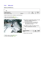
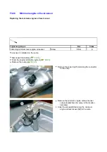
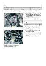


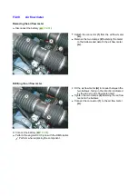


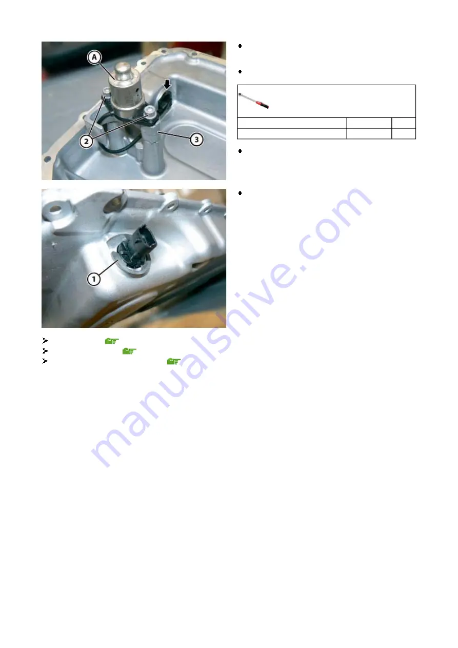
Replace the minimum engine oil level sensor,
fitting the new component in the relative seat
after aligning the holes with the shim
(3)
.
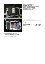
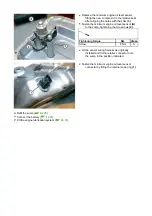
Fasten the minimum engine oil level sensor
(A)
to the sump, tightening the two screws
(2)
.
Tightening torque
Nm
Class
Screw 8
Nm
A
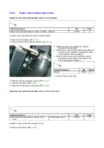
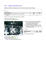
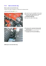
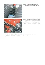
Fit the sensor wiring harness as originally
installed and fit the relative connector onto
the sump in the position indicated.
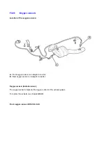
Fasten the minimum engine oil level sensor
connector by fitting the retainer snap ring
(1)
.
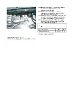
Refit the sump (
B2.05
).
Connect the battery (
F2.01
).
Fill the engine lubrication system (
A3.01
).
Summary of Contents for California
Page 19: ...Z Tyre type and pressure label ...
Page 20: ...04 02 Assembly number Assembly number A Assembly number label ...
Page 21: ...04 03 Chassis number Chassis number B Punched chassis number ...
Page 22: ...04 04 Engine type and number Engine type and number C Punched engine type and number ...
Page 23: ...04 05 Chassis number Chassis number D Chassis number ...
Page 24: ...04 06 Gearbox type and number Gearbox type and number E Gearbox type and number plate ...
Page 25: ...04 07 Vehicle identification Vehicle identification K VIN label Vehicle Identification Number ...
Page 28: ...04 10 Fuel Fuel I Fuel label ...
Page 29: ...04 11 Paintwork Paintwork L Paintwork label ...
Page 30: ...04 12 Emissions control Emissions control M Emissions control data label ...
Page 31: ...04 13 Airbag Airbag N Do not install child seat on passenger seat label ...
Page 32: ...04 14 Airbag Airbag O Airbag maintenance label ...
Page 33: ...04 15 Airbag Airbag P Airbag warning label ...
Page 43: ...Fluids and lubricants table Model Fluids and lubricants table Download ...
Page 71: ...Screw the cap A back on tightly ...
Page 104: ...Connect the battery F2 01 ...
Page 118: ...Vehicle Setup Parameter Check Form Model Vehicle Setup Parameter Check Form Download ...
Page 520: ...A DCT gearbox clutch oil tank and clutch oil pump B Clutch oil pipes C Clutch oil radiator ...
Page 623: ...CCM Brake Disc Wear Form Model All Models CCM Brake Disc Wear Form Download ...
Page 1070: ...A Horn button B Engine start button C Manettino ...
Page 1102: ...Perform the respective cycle with the DEIS diagnostic tester ...
Page 1144: ...Connect the battery F2 01 ...
Page 1220: ...Precautions and guidelines for using the RHT retractable hard top ...
Page 1334: ...Undo the indicated fasteners Retrieve the indicated shims Release the clip 1 ...
Page 1335: ...Remove the indicated clip Undo the indicated screw Undo the screws indicated ...
Page 1452: ...Refit the rear wheelhouses E3 05 Connect the battery F2 01 ...
Page 1453: ...F2 07 Lights Diagnosing condensation in headlamps ...
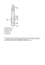
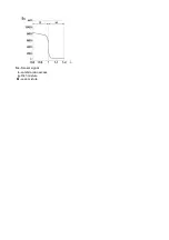
Page 1561: ...Ss Sensor signal λ Lambda ratio excess g Rich mixture M Lean mixture ...
Page 1570: ...Refit the DCT gearbox C2 03 Connect the battery F2 01 ...
Page 1656: ...G Heater evaporator H Pollen filter I Air vents M Expansion valve ...
Page 1677: ...Refit the front wheelhouses E3 05 ...
Page 1686: ...Refit the caps 1 Refit the engine compartment cosmetic shields E3 13 ...


