


F5.01
Air conditioning and heating system layout
System overview
The air conditioning and heating system automatically regulates the temperature and humidity in the
passenger compartment. The system can simultaneously and independently regulate air temperature and
distribution for the driver side zone and passenger side zone.
The A.C. system consists of a heating, ventilation and air conditioning unit (HVAC) located under the
dashboard.
The passenger compartment is split longitudinally into two temperature zones:
driver zone;
passenger zone.
The dual zone regulation system regulates the following parameters:
passenger compartment air temperature in driver zone;
air distribution via vents in driver zone;
passenger compartment air temperature in passenger zone;
air distribution via vents in passenger zone;
ventilation with external air or recirculating air in passenger compartment;
fan speed.
Functional requisites
The functions of the HVAC module, located under the dashboard, consist in aspirating air through heat
exchanger either from outside the vehicle or from inside (REC function) and in continuously adjusting the
quantity and temperature of the distributed air.
The air introduced into the vehicle must be filtered to remove particulate and odours in both external air and
REC modes.
The air temperature is regulated by altering the flow of refrigerant through the heater core in two symmetrical
crossed circuits, with one on the left-hand side and one on the right-hand side.
Air conditioning and heating system layout
The air conditioning and heating system consists of a heater/evaporator unit (HVAC) controlled by a
microprocessor ECU (integrated in the A.C. control panel) which, in both automatic and manual mode,
maintains constant temperature within the passenger compartment regardless of external conditions by
regulating the air temperature, distribution and air flow.
The system automatically selects whether to use air from outside the vehicle or air recirculated within the
passenger compartment, independently of ambient conditions.
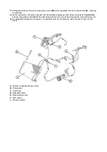
The
R134 A
refrigerant is aspirated in gaseous state by the compressor
(B)
, which sends it to the condenser
(C)
at a pressure varying in relation to ambient temperature.
When the refrigerant cools inside the condenser, it condenses and becomes a liquid.
The dehydrator filter, which is built into the radiator assembly, removes all traces of humidity due to water
vapour in the system and acts as a tank for the liquid refrigerant.
A pressure switch
(L)
in this part of the system measures the pressure and disengages the electromagnetic
clutch when the pressure limit is reached.
Summary of Contents for California
Page 19: ...Z Tyre type and pressure label ...
Page 20: ...04 02 Assembly number Assembly number A Assembly number label ...
Page 21: ...04 03 Chassis number Chassis number B Punched chassis number ...
Page 22: ...04 04 Engine type and number Engine type and number C Punched engine type and number ...
Page 23: ...04 05 Chassis number Chassis number D Chassis number ...
Page 24: ...04 06 Gearbox type and number Gearbox type and number E Gearbox type and number plate ...
Page 25: ...04 07 Vehicle identification Vehicle identification K VIN label Vehicle Identification Number ...
Page 28: ...04 10 Fuel Fuel I Fuel label ...
Page 29: ...04 11 Paintwork Paintwork L Paintwork label ...
Page 30: ...04 12 Emissions control Emissions control M Emissions control data label ...
Page 31: ...04 13 Airbag Airbag N Do not install child seat on passenger seat label ...
Page 32: ...04 14 Airbag Airbag O Airbag maintenance label ...
Page 33: ...04 15 Airbag Airbag P Airbag warning label ...
Page 43: ...Fluids and lubricants table Model Fluids and lubricants table Download ...
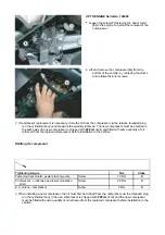
Page 71: ...Screw the cap A back on tightly ...
Page 104: ...Connect the battery F2 01 ...
Page 118: ...Vehicle Setup Parameter Check Form Model Vehicle Setup Parameter Check Form Download ...
Page 520: ...A DCT gearbox clutch oil tank and clutch oil pump B Clutch oil pipes C Clutch oil radiator ...
Page 623: ...CCM Brake Disc Wear Form Model All Models CCM Brake Disc Wear Form Download ...
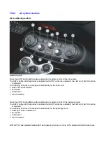
Page 1070: ...A Horn button B Engine start button C Manettino ...
Page 1102: ...Perform the respective cycle with the DEIS diagnostic tester ...
Page 1144: ...Connect the battery F2 01 ...
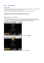
Page 1220: ...Precautions and guidelines for using the RHT retractable hard top ...
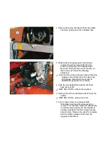
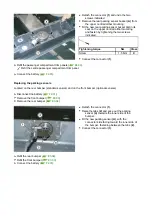
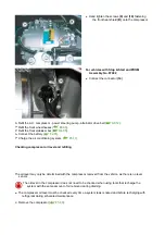
Page 1334: ...Undo the indicated fasteners Retrieve the indicated shims Release the clip 1 ...
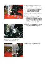
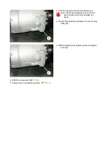
Page 1335: ...Remove the indicated clip Undo the indicated screw Undo the screws indicated ...
Page 1452: ...Refit the rear wheelhouses E3 05 Connect the battery F2 01 ...
Page 1453: ...F2 07 Lights Diagnosing condensation in headlamps ...
Page 1561: ...Ss Sensor signal λ Lambda ratio excess g Rich mixture M Lean mixture ...
Page 1570: ...Refit the DCT gearbox C2 03 Connect the battery F2 01 ...
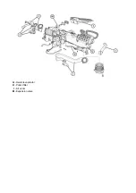
Page 1656: ...G Heater evaporator H Pollen filter I Air vents M Expansion valve ...
Page 1677: ...Refit the front wheelhouses E3 05 ...
Page 1686: ...Refit the caps 1 Refit the engine compartment cosmetic shields E3 13 ...


