background image

12

Kongsberg X-series

12.9.2.  Chiller, Error Conditions

One common error signal is routed from the 

Chiller

 system to the

inverter and further into the control system.

The following error conditions are monitored:

• Temperature out of range (high and low)
• Liquid flow too low (less than 0.5 l/min). The signal is 1 minute

delayed.

• Temperature sensor failure


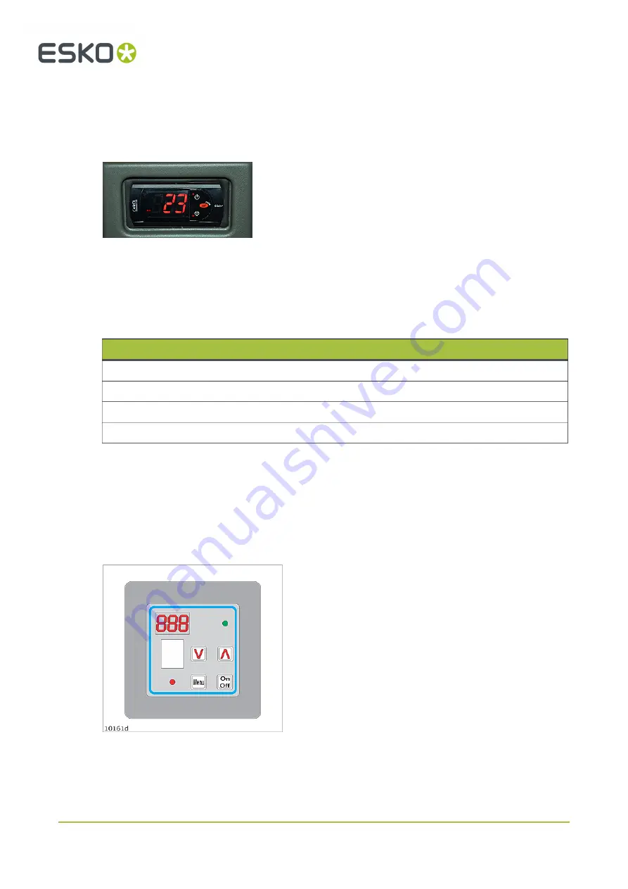
If any chiller failure occurs, you have to look at the chiller display to see the real reason for the problem:

Code

Description

E0

Sensor failure: cable defective, connection failure, sensor defective.

IA

Water level of water flow too low.  

HI

Temperature of cooling medium too high  

LO

Temperature of cooling medium too low  

During normal operation, the cooling medium temperature is displayed.  

More information is available from the Operating instructions for the chiller.

12.9.3.  Chiller Heater, Operation

Notes:

1.

The 

Chiller Heater

 is optional.

2.

The 

Chiller Heater

 must be filled with water

before connecting mains.

3.

The 

Chiller Heater

 is correctly configured

when shipped from the factory. Normally, there
is no need for modifications.

Some operating instructions are included here if
any modifications are still needed.

120

Summary of Contents for Kongsberg X Series

Page 1: ...Kongsberg X series User Manual 09 2020 X series...

Page 2: ...rators 18 5 4 De nition of use 19 5 5 Warning sign explanation 19 5 6 Attention areas 22 5 6 1 Mains power disconnection 22 5 6 2 High voltage laser radiation and moving parts 23 5 6 3 Loose clothing...

Page 3: ...Grain Direction 42 8 7 Vacuum Zone Selection 42 8 8 Job Execution 43 8 9 Milling Production 43 8 10 Make a Pen Plot 44 8 11 Work with X Pad 44 9 How To Procedures Advanced 48 9 1 Cutting Thick Materia...

Page 4: ...adjustment of Center Offset and angle 69 11 8 Tool Offset 69 11 9 Maintain Tool List More 70 12 Tooling System 72 12 1 Tool handling and care 72 12 2 Tool Inserts with built in motor 72 12 3 Tool Head...

Page 5: ...123 12 10 3 Error Conditions 123 12 11 Measuring Foot 124 12 12 Laser Pointer 125 12 13 X Pad 126 12 13 1 X Pad Calibration 126 12 13 2 Tool Depth and X Pad 127 12 13 3 Limitations 127 13 Tool insert...

Page 6: ...t 163 14 Maintenance 165 14 1 Daily maintenance 165 14 2 Weekly maintenance 165 14 3 Maintenance external equipment 165 14 4 Maintenance i BF board feeder 166 14 4 1 About maintenance 166 14 5 Mainten...

Page 7: ...rip Shaft 201 19 6 3 Feeding the material through the MRF onto the table 201 19 6 4 End of production 204 19 6 5 Intelligent vacuum 204 19 7 Safety 204 19 8 Jobs longer than table 205 19 9 Understandi...

Page 8: ...Ze ro 233 21 1 1 How to use 233 21 2 Vacuum Cleaner High capacity TB ESKO 235 21 2 1 How to use 235 21 3 Compact Vacuum Cleaner 238 21 3 1 How to use 238 22 Install Software 240 23 Frequently Asked Qu...

Page 9: ...Kongsberg AS does not warrant guarantee or make any representations regarding the use or the results of the use of the system or the information contained herein Esko Graphics Kongsberg AS shall not b...

Page 10: ...12 2016 jhbe MultiCUT HP chapters updated 03 02 2017 jhbe TakeUp Unit information added 15 02 2017 jhbe MultiCUT Sleeve Adjustment Tool information added 28 02 2017 jhbe i BF Board Feeder information...

Page 11: ...length and position updated 20 02 2020 DHO Safety sections misc updated 06 03 2020 DHO Updated for Chiller 2020 03 04 2020 DHO Safety sections updated 08 06 2020 DHO FCC conformity statement added 14...

Page 12: ...sole iPC Thus actual GUI functions will be referenced in this manual but the complete and comprehensive description is available in the User Manual for i cut Production Console This manual is aimed fo...

Page 13: ...llation This equipment generates uses and can radiate radio frequency energy and if not installed and used in accordance with the instructions may cause harmful interference to radio communications Ho...

Page 14: ...machine Prepare for a Job A typical work ow is described with detailed information about each step How to Procedures Advanced Optional functions for the advanced user Cutting Thick Materials advices...

Page 15: ...panel OK The bold style indicates this is a button or function in the GUI Maintenance Link to topic Menu Bar Edit Options Menu selection From Menu Bar select Edit and then Options This symbol indicate...

Page 16: ...4 Kongsberg X series 4 4 Local Languages This manual is available in a wide range of local languages Screen pictures and illustrations remains in English language 16...

Page 17: ...to stop and any contact with a rotating milling bit is very dangerous Use appropriate techniques and tools when handling heavy materials The machine has fast moving parts like the traverse and tool h...

Page 18: ...ibed in safety regulation as well as any other safety warnings Training will be given to operator s nominated by the customer by the Esko service engineer as part of the system installation The traini...

Page 19: ...i ed by Esko Operating or maintaining the machine or any of its accessories under the in uence of drugs alcohol or medication that could impair your judgment and vigilance Non intended use may cause H...

Page 20: ...s unit until the mains connection has been removed from the socket outlet for the IBAG inverter Note Different instruction for Cxx and Xxx Chiller The chiller is not disconnected by the mains connecti...

Page 21: ...s used in this documentation to indicate operations with Knife Blades and Milling bits Hand Squeeze Potential areas with a risk of being squeezed are marked with the Hand Squeeze sign These areas are...

Page 22: ...ry Do not leave the machine running if the vacuum cleaner can be over lled This might cause damage or in worst case a re if the suction house is clogged See also Safety issues on page 95 in the sectio...

Page 23: ...adiation and moving parts 5 6 3 Loose clothing While working with this machine do not wear clothes or jewelry that can entangle with moving parts of the machine Ties Loose necklaces Scarfs 5 6 4 Noise...

Page 24: ...lling bit has come to a complete standstill before touching it Note Only specially trained operators are allowed to operate milling tools 5 6 7 i Camera strobing light If your system includes i Camera...

Page 25: ...arning lamp status lamp Y carriage milling spindle running milling unit 4 DynaGuard safety system 5 Traverse stop switches DynaGuard safety system Yellow black tape on the oor to indicate attention ar...

Page 26: ...by pressing the Pause Servo on pushbutton 4 Observe that servo power is switched on 5 Press Start to continue 5 7 3 Yellow black tape The yellow black tape indicates the attention area This area is r...

Page 27: ...inue after DynaGuard is triggered To continue operation proceed as follows 1 Ensure the table is free from obstructions and ready for operation 2 Reset the Safety System by pressing the Pause pushbutt...

Page 28: ...tic noise level will vary with the type of operation and tooling but a typical average level is 78 5 83 5 dBA and a maximum level of 98 5 dBA 5 9 Procedures in case of Malfunctions Trouble shooting an...

Page 29: ...ware of Beneath traverse end The lower part of the traverse end is un protected Actions Children are not supposed to be inside the machine safety attention area Do not work or stay beneath the travers...

Page 30: ...nics is reduced Actions Stay out of this area while the machine is operating Inside cable chain There is a risk for squeezing between the cable chain and the table frame Actions Stay out of this area...

Page 31: ...up to 4 seconds This is su cient time to access and touch the milling bit before it has come to a complete stop It is crucial that the operator always ensures by visual inspection that the milling bit...

Page 32: ...6 1 Naming conventions X series 1 Table top 6 Main Power on off switch 2 Y carriage 7 Operator Panel 3 Traverse 8 Emergency Stop button 4 Tools 9 Traverse Safety Stop switches DynaGuard 5 Main Power U...

Page 33: ...The arrows indicates positive moving direction 6 2 Main Power Switch Switch positions O the Main Power to the machine is switched OFF I the Main Power to the machine is switched ON 6 3 Operators Pane...

Page 34: ...t button to move the Tool Head to Selected Reference Point The Table Zero Mode is automatically selected at Power on The system remains in the Table Zero Mode until Table Zero Sequence is completed Jo...

Page 35: ...Machine Con guration Setup Tool Down Press the Tool Down button to manually operate the machine with a tool in the down position Cancel by pressing Tool Down a second time Vacuum release mode For deta...

Page 36: ...General The High Pressure Air System supplies the valves and tooling with compressed air The compressed air input is connected to a combined Pressure Regulator Valve Water Trap Wall Outlet Wall Outlet...

Page 37: ...Air Pressure Regulator 6 6 Application programs available After installation of iPC the following application programs are available iPC Control program for the Cutting Table For more information see...

Page 38: ...the table is free from obstructions and ready for operation Follow these steps to power up the system and get ready to work 1 Front End PC Switch on the PC and the monitor 2 Table Power Switch the ta...

Page 39: ...iPC The spindle warning lamp red should ash shortly and then light constantly This indicates that the spindle rotates Any malfunction of the lamp must be corrected as soon as possible since the lamp i...

Page 40: ...table are stopped and the Warning Lamp starts ashing To continue operation proceed as follows 1 Ensure the table is free from obstructions and ready for operation 2 Reset the Safety System by pressin...

Page 41: ...arting Point in this procedure is to Create a Job from a le already available in My Jobs List Detailed information about the complete iPC work ow is available in the following manuals User Manual for...

Page 42: ...b Position Step and Repeat Registration Material Handling Tool Head Parking 8 5 Speed Setting Opened Job Production Setup Quality Specify if this is a High Accuracy or a High Speed Job 8 6 Flute Grain...

Page 43: ...pened Job is ready for production 2 Verify that the Table View display of the Job is reasonable 3 Press Pause to reset Safety System 4 Complete a Table Top Reference sequence to update Tool Height mea...

Page 44: ...nd execute a job Ensure the Ballpoint Pen is clean and ready to use 8 11 Work with X Pad Measuring modes Machine Connection Machine Con guration Setup Two modes are available Manual Tool height is man...

Page 45: ...asuring sequence is started 3 Place the measuring pad with the Laser spot in center or jog the machine until the Laser spot is in the middle of the measuring pad Press Start to initiate measuring Indi...

Page 46: ...Measuring Pad Negative value means down into the material Current offset setting The initial offset value when the dialog was opened is displayed How to start a measuring sequence in the middle of a j...

Page 47: ...8 Kongsberg X series How to cancel measuring or calibration All Measuring Pad operations are cancelled by Press Close in the active dialog Press Pause on Operators Panel 47...

Page 48: ...Knife Tools only Cutting Depth when Depth Referenced from Top is disabled Note This function is useful for all materials with an un even surface 9 2 Hard Board Production To prepare hard board materia...

Page 49: ...ion Reverse Operation is used if operations need to be done from both sides There are two types of Reverse Operations Ruler based Camera based Which methode is available is HW dependant and described...

Page 50: ...ected tool does not currently allow reverse side operation Can be con gured in Con gure Tools dialog Status 2 Selected tool allows reverse side operation Turned off Status 3 Selected tool allows rever...

Page 51: ...Crease line on the front side of a material that you normally prepare from the rear side This function requires that the table has Left and Right Rulers physically mounted and selected in HW con gura...

Page 52: ...se Operations in combination with Step and Repeat and Left and Right Ruler For each copy de ned by Step and Repeat you have to move the sheet rst against the Right Ruler then against the Left Ruler Re...

Page 53: ...tiZone Production is available In this chapter more machine speci c issues are described MZP Panel Each work zone is equipped with a panel that makes it possible to run the complete MultiZone Producti...

Page 54: ...able for MultiZone Production Limitations The last section of a multizone table is somewhat smaller than the rst one s As a consequence the work area available for MultiZone Production is determined b...

Page 55: ...will move into the other zone photo cell beams traverse end cover To ensure a continous work ow the operator should be very careful inside the Attention Area not to trigger the safety system by his bo...

Page 56: ...roper settings One time adjustments completed at the factory The functions are included here as a reference They are not used during normal operation If necessary they should be repeated as indicated...

Page 57: ...he Adjust X1 to X2 Angle function 2 Follow the instructions exactly as given by the wizard Note Select a set of drilled vacuum holes 1 and 2 in the table top as reference 10 3 Register Table Size Mach...

Page 58: ...Main Reference Position Follow instructions from the wizard Use this wizard to establish the Main Reference Point R Typical use is after maintenance or repair if the Main Reference Point has been acc...

Page 59: ...based on table top mapping A registry setting is available to enable the old behavior 10 7 Reference Points and Coordinate System Reference Points settings is maintained from Menu Bar Edit Options Ref...

Page 60: ...Reference Point R A special version of User De ned Reference Point is the Panel Reference Point 1 Position the Laser Pointer in the position where you want your Panel Reference Point 2 Press the Set...

Page 61: ...ayers are created Opened Job Edit Layer Speed X Y Modify Speed for this particular Job Opened Job Production Setup Quality Here you specify if this is a High Quality Job or High Speed Job 10 9 Table A...

Page 62: ...eference Follow instructions from the wizard Machine Panel Toolbar Table Top Reference Use this function to complete a Tool Height Reference calibration The Tool Height is measured in current position...

Page 63: ...Specify Milling unit If a milling unit is mounded spedify milling unit type If no milling unit is mounted select None COM port The physical COM port used for communication with the control unit is sp...

Page 64: ...onnection Tool Con guration The Tool Con guration dialog is used for all tool settings and adjustments 11 2 Adjust Active Tool From the Adjust Selected Tool dialog all Tool Adjustment Wizards are exec...

Page 65: ...able Top Reference 11 3 Tool Height Calibration 1 Select the Tool to be adjusted 2 Press the Adjust Active Tool button to enter the wizard selection dialog 3 Select Tool Height Calibration 4 Follow th...

Page 66: ...back of the Knife Blade Enter the value as measured or as found using the Lag test see below Width knife bottom width Enter the measured knife bottom width Lag Test Run this wizard to obtain correct K...

Page 67: ...ter the wizard selection dialog 3 Select Rotation adjustment 4 Follow the instructions given by the wizard step by step 5 Repeat the procedure for all Tools mounted Manual Adjustment 1 Place an approp...

Page 68: ...isleading offset in this wizard 2 Switch vacuum on 3 Select the Tool to be adjusted 4 Press the Adjust Active tool button to enter the wizard selection dialog 5 Select Center Offset Adjustment 6 Follo...

Page 69: ...nts obtained using the wizards Use this dialog to modify the adjustment values for angle and center offset 1 Select the tool to be adjusted 2 Press the Manual adjustment of button to enter the adjustm...

Page 70: ...by step 11 9 Maintain Tool List More The More dialog contains selections to Ignore Delete or Add to the Tool List The Tool List contains Tools that you can select for the available Tool Positions Igno...

Page 71: ...11 Kongsberg X series Add new Tools Add tools that fails during Automatic Tool Detection The Tool is added to the Tool List 71...

Page 72: ...inserted or removed from their stations No excessive force should be applied Tools should not come in contact with hard surfaces while removed from their stations either temporarily or for storage Th...

Page 73: ...ut RotaCut Knife Drill Tool Pen Foam Knife PowerHead PowerHead is a special purpose Tool Head which can be equipped as follows Two general tool positions prepared for the standard FlexiHead tools Powe...

Page 74: ...d which can be equipped as follows Two general tool positions prepared for the standard FlexiHead tools Milling tool equipped with a high speed milling spindle 12 4 Tool Head mount dismount Be careful...

Page 75: ...ring foot material hold down foot Has 3 functions a Measure the thickness of the material on the table b Mapping Table Top Surface c Keep material down during knife operations Replace a Tool Insert Ob...

Page 76: ...just offset to Laser Pointer 12 6 PowerHead Tool Head Description 1 Tool position 1 FlexiHead tool insert 2 Tool position 2 FlexiHead tool insert 3 Tool position 3 4 Laser Pointer 5 Measuring foot mat...

Page 77: ...wizards see Tool Con guration 12 6 1 150 mm Crease Wheel This Crease Wheel has the equivalent of 50kg 110lb of down pressure The additional pressure combined with the large frontal area of the big whe...

Page 78: ...in crease wheels to be used in the Heavy Duty crease tool position The tool is adjusted and operates as an ordinary crease tool 12 6 3 Perforation Wheel 60 mm Use Perforation Wheel to prepare perfora...

Page 79: ...12 Kongsberg X series Perforation Wheel assembly Parts in assembly Ensure the path is clean Fix cover properly Push pull the perforation wheel in out from the adapter 79...

Page 80: ...gle tangential to Moving Direction Center Offset Adjust Tool sideways until centered Tool Offset Adjust offset relative to Laser Pointer For more information about how to run the Adjustment Wizards se...

Page 81: ...series 12 6 5 V notch Knife V notch Knife mounted on a Heavy Duty Unit How to insert remove V notch Knife Turn the V notch Knife A correctly to t the alignment pin B Both latch pins are used for the V...

Page 82: ...ect height of the new knife Tool adjustment For the V notch Knife we recommend the manual procedures for tool rotation and centre offset adjustment When adjusting tool rotation and centre offset use a...

Page 83: ...Layer How to set the depth of the V notch Knife 1 The default depth of the V notch Knife is cut through the entire material 2 De ne the depth of the V notch cut in the dialog 3 Normally the cut shoul...

Page 84: ...operation Opened Job Layers Tab Edit Layer Menu Bar Layer Edit Layer Note V notch Knife Adapters are available for different knife angles 15 o 22 5 o 30 o 45 o 47 5 o There is also a VariAngle unit a...

Page 85: ...nical exibility in the system Notch angle Notch Angle is used for the VariAngle unit only and determines the angle of the blade into the material 0 o is a vertical cut For V notch knifes angle is dete...

Page 86: ...cutting depth to just above the bottom liner Adjust the cutting width W by the adjustment parameter Width Offset Nominally the width of the cut has to be increased by Width Offset 2 x bottom liner thi...

Page 87: ...aking the material impossible to fold The Triple Cut Function 1 cut the middle wall and you can fold the material nicely Adjustment sign and cut direction 12 6 6 Bevel Knife 45 Bevel Knife is a specia...

Page 88: ...Tool Height Correct tool height relative to table top Lag Setting Default lag value for the long foam knife is 4 5mm 0 18 Tool Rotation Adjust tool angle tangential to moving direction Center Offset...

Page 89: ...btain best quality when cutting details as small circles we recommend Reduce the cutting speed from Job Setup Cut in two or three passes each pass going a step deeper Multi pass How to replace a Knife...

Page 90: ...Disable Material Thickness Measurement function is enabled the following rules applies Depth is referenced from bottom top of cutting underlay During Tool Up movements the knife is lifted to its top...

Page 91: ...Be aware that the chucks for HF 45 MultiCUT and HF 62 MultiCUT HP are different and they cannot interchange Replacing a chuck Replacing a chuck is described in detail in Chuck Change and Cleaning on p...

Page 92: ...Laser pointer 4 Tool position 3 5 Measuring foot material hold down foot 6 Electrical connection milling spindle 7 Electrical connection reciprocating motor 8 Suction tube 9 Cooling water connectors 1...

Page 93: ...huck on a dummy bit When the tool head is disconnected from the traverse a dummy bit should always be used to prevent injury from a sharp milling bit 5 Air Clean Button to help remove contamination 6...

Page 94: ...is xed to the suction house When the milling tool is not in use the tubes are xed to the gallows as shown here Chiller MultiCUT HP start up time Depending upon the environmental temperature the Chill...

Page 95: ...cessive wear Using milling bits with extended length at high RPM can also be dangerous Therefore using long milling bits is subject to an automatic RPM reduction If you are using short 8 mm bit these...

Page 96: ...ner full Follow the Vacuum Cleaner lling level carefully Empty the container before the level reach the inlet position indicated in red Suction house Always when executing a job let the suction house...

Page 97: ...stop time The milling spindle does not stop instantly Always ensure that the red lamp has stopped ashing and by visual inspection that the milling bit has come to a complete standstill before touchin...

Page 98: ...ions for the motor and immediate actions should be taken 1 Use correct and sharp milling bit 2 Use correct RPM for the actual bit and material 3 Reduce the X Y speed If the motor is running above a cr...

Page 99: ...connected This will destroy the Spindle Use Clean Air The Spindle is sensitive for the Pressurized Air quality Regularly check the Air Pressure Reduction Valve according to the Maintenance on page 165...

Page 100: ...l depend on the type of operation and is di cult to predict Indication of worn bearings may be increasing noise increasing vibrations or decreasing surface nish Note When replacing a Spindle torque th...

Page 101: ...ng advice Follow this advice for obtaining the best possible milling results Milling bits For thin materials use bits with short cutting length For best performance and minimum wear do not let the bit...

Page 102: ...meter 3 4 mm 0 12 0 16 in are more balanced than bits with larger cutting diameter Thus they can run with higher RPM normally 60 000 Use large diameter bits 5 6 mm 0 20 0 24 in when needed only Typica...

Page 103: ...9 ips at 60 000 RPM Light materials like PVC foam can be run much faster The surface nish or the Power Consumption will normally determine the nal Feed Rate for an application A large drop in RPM or a...

Page 104: ...to reduce the acceleration in order to achieve an optimal Cutting Quality when combining a heavy tool head with high quality cutting tools 12 8 7 Cleaner Device Cleaning the suction house is simple us...

Page 105: ...ck Open Close lever down to open the Chuck Put the bit in a proper storage container Insert a new milling bit Close the Chuck 3 Only the round part of the shaft should be inside the Chuck See the Bit...

Page 106: ...rent depths Use the Sleeve Adjustment Tool in order to Ensure correct insertion of milling bit Ensure equal bit height when replacing a milling bit Additional tool height adjustment not necessary Safe...

Page 107: ...Cleaning on page 107 section about how to unscrew the chuck 12 8 9 Chuck Change and Cleaning Clean the taper and the chuck regularly for proper operation and optimum life time at least once a week but...

Page 108: ...ly Compressed Air for cleaning 2 Apply the 17 mm key to hold the Spindle Rotor Note Do not turn the rotor when Chuck is in open position This might damage the Spindle 3 Enter the Chuck Tool with a Dum...

Page 109: ...must be pressurized 5 Use the Taper Brush to clean the Taper 6 Push the Air Clean Button to help remove contamination 7 The Taper Brush must be absolutely free from grease or oil If necessary you must...

Page 110: ...green arrows Avoid the clamping area red arrow Do not use oil as it could enter the clamping area and reduce the clamping force 9 Torque up the chuck by hand using the Chuck Tool with a Dummy Bit Hold...

Page 111: ...re 12 8 11 Bit Length and Position Keep distance d small For best performance and minimum wear do not let the bit stick out more than necessary Use bits with short cutting lengths for thin materials F...

Page 112: ...Adjustment For FlexiHead tool positions complete relevant adjustments as described for FlexiHead For the milling unit position complete the following adjustments Tool Height Correct tool height relat...

Page 113: ...ther test material Note This adjustment can be completed both on surface U and M not on C but we recommend the described solution The following rules apply when milling Mill on cutting underlay C To a...

Page 114: ...n the suction house when necessary with acetone and a q tip A smooth surface will ease the chip removal Vacuum clean the milling underlay The Vacuum Cleaner can be used for automatic cleaning of the f...

Page 115: ...12 Kongsberg X series Introduction LubriCool mounted on MultiCUT HP A inspection window B Suction cup with nozzles LubriCool control unit How to use 115...

Page 116: ...ation is not suitable use the ON OFF switch on the LubriCool Control Unit to switch off lubrication Inspection Opening When the LubriCool unit is on you can see light in the control relays inside the...

Page 117: ...ush and with bigger suction opening Use the Nozzle Unit when the LubriCool function is bene cial only For all other materials especially MDF use the Suction Ring Note It is crucial for proper operatio...

Page 118: ...il tube from the outlet Nozzle Unit with oil tube Cleaning Proper cleaning is crucial for correct operation Release locker A and remove the nozzle unit Use vacuum cleaner to clean MultiCUT HP suction...

Page 119: ...ultiCUT HP 12 9 1 Introduction This is chiller 1 replaced in October 2016 by a new model named chiller2016 Flow Measurement During operation check the water ow level displayed on the chiller meter For...

Page 120: ...ensor failure cable defective connection failure sensor defective IA Water level of water ow too low HI Temperature of cooling medium too high LO Temperature of cooling medium too low During normal op...

Page 121: ...ng elements are operating Red light on fault condition over heating cable breakdown Program selection Press and hold the Menu button for 3 sec Use arrow keys to select program Press Menu button to con...

Page 122: ...ced those years Chiller 2020 differs from previous models by being a heat exchanger which will not be able to lower the temperature below ambient Speci cations Dimensions W x D x H 480 x 580 x 430 mm...

Page 123: ...9 o C 66 o F The chiller is equipped with an internal automatic heater First time startup Check that the supply matches the rated voltage Check that the electrical connection has been made correctly 1...

Page 124: ...5 o F L1 Temperature of cooling medium too low 19 o C 66 o F Continue after error situation Find root cause for the error situation and x it Flow too low is normally caused by a squeezed water hose Sw...

Page 125: ...2 Laser Pointer The Laser Pointer L in the illustration is a Class II laser beam pointing device Wavelength 650 nm 1 mW The Laser Pointer is used in adjustment wizards and job execution to indicate cu...

Page 126: ...ried out Ballpoint Pen Tool Braille Tool CorruSpeed Knife Tool Drill Tool MultiCUT MultiCUT HP Psaligraphy Knife Tool RM Knife Tool Procedure The calibration wizard is initiated from Option Table Opti...

Page 127: ...red in two ways 1 The general depth of a tool is entered in Menu Bar Advanced Con gure Tools menu 2 The depth for a certain job is entered in Layer Setup 12 13 3 Limitations The following tools can be...

Page 128: ...top of the tool Ball Point Pen tool is prepared for Space Pen re lls Tool assembly and pressure adjustment A Inner sleeve The ball point pen re ll is xed inside the sleeve using a screw Use Allen Key...

Page 129: ...4 in How to replace a Knife Blade Loosen the two screws holding the blade clamp Pull out the old Knife Blade Insert the new blade Ensure the blade align exactly with the alignment pins Fix the blade c...

Page 130: ...tructure and thickness For optimal result a ne tuning of the adjustments in the actual material should be carried out For more information about how to run the adjustment wizards see Tool Con guration...

Page 131: ...htly 5 Push the dispensing mechanism up 6 One sphere should be pushed out from the tool Plunger The tool is equipped with a plunger that serves two purposes 1 To force the spheres into the internal fu...

Page 132: ...s Meaning if the material is 6 mm thick the nominal height setting should be 6 mm minus 6 mm Tool Offset adjustment Machine Connection Tool Con guration 1 Load the Braille Tool with black spheres 2 Cu...

Page 133: ...ed Con gure Tools Braille Tool should be de ned with the following parameters enabled Velocity Z max speed Z axis Depth 0 Drill holes on Preparing Layers for Braille Tool Opened Job Layers Edit Layers...

Page 134: ...high The standard speci es a sphere height of 0 6mm 0 023 Example using 3mm Dibond 1 07mm 3mm 1 93mm Spindle RPM Spindle RPM is material dependent and may require experimentation The values shown in...

Page 135: ...Operations in the desktop publishing software To create the Braille patterns select the Braille font and type the text Select a font size which gives correct distance between the dots patterns Details...

Page 136: ...d is 1 0 mm 0 04 in less than material thickness One turn CW on A increase d with 1 mm 0 04 in B Foot pressure Adjust foot pressure C scale indicating actual pressure For optimal performance the foot...

Page 137: ...justment For this tool complete the following adjustments Parameter Description Tool Height The tool tip should touch the material surface Lag Setting The knife lag depends upon the actual knife blade...

Page 138: ...6 1 Tool adjustment For this tool complete the following adjustments Parameter Description Tool Height The tool tip should touch the material surface Lag Setting The knife lag depends upon the actual...

Page 139: ...mm The crease wheel is attached to the tool after it has been mounted in the Tool Head Note When working with thin materials avoid crease close to the Ruler 13 7 1 Tool adjustment For this tool comple...

Page 140: ...Tool Offset Adjust offset relative to Laser Pointer For more information about how to run the adjustment wizards see Tool Con guration 13 8 Drill tools 13 8 1 Flexi Drill Tool How to replace a drill b...

Page 141: ...ed for drill bits 0 5 6 mm 0 02 0 24 inches The motor RPM is adjustable from 100 1000 speci ed in Layer Setup Inside one job only one RPM is available If different RPMs are speci ed the highest value...

Page 142: ...rill Tool in Sample Making see Service Guide for ArtiosCAD Kongsberg integration available on the documentation DVD 13 9 Foam Knife The Foam Knife tool for FlexiHead is a special purpose tool for cutt...

Page 143: ...m 0 1 How to replace a Knife Blade Follow instructions for Static Knife 13 10 Ink Tool Two ink tool models are available Liquid Ink Tool and Fibertip Tool Lag is nominal 0 mm 13 10 1 Liquid Ink Tool L...

Page 144: ...nk tool assembly 13 10 2 Fibertip Tool Fibertip Tool is for ink drawing The tool is prepared for Staedtler Lumocolor insert Fibertip tool assembly 13 10 3 Tool adjustment For this tool complete the fo...

Page 145: ...ore information about how to run the adjustment wizards see Tool Con guration 13 11 KissCut KissCut is a special knife tool for vinyl cutting The cutting depth is controlled by the downward knife pres...

Page 146: ...his hand tool when removing and inserting knives into the tool When inserting a new Knife Blade ensure the blade is correctly positioned relative to the Alignment Pin Tool pressure Knife pressure is a...

Page 147: ...ter and knife blade Normally lag 0 Tool Rotation Adjust tool angle tangential to moving direction Center Offset Adjust tool sideways until centered Tool Offset Adjust offset relative to Laser Pointer...

Page 148: ...the Tool Head 2 Remove the sliding sleeve from the tool 3 The Knife Blade is held by a hex screw A 1 5 mm key will t 4 Loosen the hex screw and insert the new blade 5 When inserting the new blade ple...

Page 149: ...nd folding carton Lag is nominal 0 mm Replace Knife Blade For Knife Blade change remove the foot The locking screw will always point towards the cutting direction Note Be extremely careful when mounti...

Page 150: ...o Laser Pointer For more information about how to run the adjustment wizards see Tool Con guration 13 14 RBI 90 16 Rigid Board Insert Insert remove Knife Blade Ensure the blade is correctly aligned Us...

Page 151: ...tment wizards see Tool Con guration 13 15 Reciprocating Knife Reciprocating Knife is available in two models Reciprocating Knife Running with 6000 RPM and amplitude 0 15 mm 0 006 inches this tool is r...

Page 152: ...tion relative to the screw Push the knife down while the screw is xed Extreme care should be taken when inserting the knife foot again Keep ngers away from knife as illustrated at left 13 15 1 Tool ad...

Page 153: ...zards see Tool Con guration 13 16 Rigid Material Knife Insert remove knife blade Ensure the blade is correctly aligned Use a 3 mm Allen Key to x loosen the knife blade After a blade change the tool de...

Page 154: ...ds see Tool Con guration 13 17 RotaCut RotaCut is a special tool for cutting light materials as thin fabric Maximum cutting depth is 2 mm 0 07 inch Note Due to the characteristics of this knife tool s...

Page 155: ...ns in the dialog Be careful though not to adjust the cutting depth too deep into the cutting underlay gure at left U cutting underlay M material D X Y moving direction For more information about how t...

Page 156: ...eft Note This operation has to be carried out after the tool insert is in place in the tool head Push the foot into position A self locking mechanism ensures the foot is kept in place Note Be careful...

Page 157: ...See above Tool Height See above Tool Rotation Adjust tool angle tangential to moving direction Center Offset Adjust tool sideways until centered Tool Offset Adjust offset relative to laser pointer Fo...

Page 158: ...s tool complete the following adjustments Parameter Description Tool Height The tool tip should touch the material surface Lag Setting The knife lag depends upon the actual knife blade adapter and kni...

Page 159: ...1 VIxx Knife Tool Mounting Adjustment Remove the knife adapter from the tool and insert the upper part into the tool position Position the tool adapter onto the shaft Observe Alignment Pin orientatio...

Page 160: ...About tool adjustment For the VIxx Knife Tool we recommend the manual procedures for tool rotation and centre offset adjustment Use a thin Folding Carton material when adjusting tool rotation and cen...

Page 161: ...1 VIxx Knife Tool Mounting Adjustment Remove the knife adapter from the tool and insert the upper part into the tool position Position the tool adapter onto the shaft Observe Alignment Pin orientation...

Page 162: ...the VIxx Knife Tool we recommend the manual procedures for tool rotation and centre offset adjustment Use a thin Folding Carton material when adjusting tool rotation and centre offset Remember that y...

Page 163: ...on the tool adapter onto the shaft Observe Alignment Pin orientation Keep the knife adapter in this position while you turn the tool shaft in order to lock the tool adapter in its position How to set...

Page 164: ...e offset adjustment Use a thin Folding Carton material when adjusting tool rotation and centre offset Remember that you should look at the bottom side of the material for correct alignment The adjustm...

Page 165: ...hould be thoroughly cleaned and oiled very lightly The automatic draining action of the air pressure reduction valve should be controlled Switch off the air compressor and allow the air pressure to fa...

Page 166: ...y maintenance 1 Inspect vacuum cups for cuts wear or damage 2 The main air lter regulator includes a coalescing moisture lter Water may accumulate in the bowl of the lter regulator To remove water dis...

Page 167: ...it is worn out 14 5 2 Spare Parts Spare parts available Part no Description 42468512 TAKEUP_GASSPRING 42468520 TAKEUP_GASSPRING GUIDING ROLLER 42468538 TAKEUP_ TOP GUIDING ROLLER 42468546 TAKEUP_POTE...

Page 168: ...8 MRF Worm geared motor 42476036 MRF Castor xed 42471508 MRF Potentiometer dancer 42476051 MRF Bearing ange Dancer 42476069 MRF Motor side shift 42476077 MRF Gearbox side shift 42471482 MRF Edge contr...

Page 169: ...ies Part no Description 42476184 Fuse 5x20 mm glass T100mA 42468579 MRF TAKEUP Switch Emergency Stop 42471490 MRF Edge sensor spiral cable 42471466 MRF Edge control fork sensor 42471474 MRF Edge motor...

Page 170: ...cedure Switch Power Off using the Main Power Switch Remove the Main Power plug from the wall socket Note Some equipment described might be optional 15 1 MPU fuses MPU Location Note MPU location is mod...

Page 171: ...n replace with a new identical fuse 4 Repeat for each fuse 5 Replace base cover 6 Insert main power cable into the wall socket and turn main power ON Fuse Details Fuse location 115V 230V F1 and F2 lin...

Page 172: ...A ampli er X1 Procedure 1 Remove X1 cover 2 Check the X1 fuse with ohm meter If blown replace with a new identical fuse 3 Replace covers 4 Insert main power cable into the wall socket and turn main po...

Page 173: ...i er X2 Procedure 1 Remove X2 cover 2 Check the X2 fuse with ohm meter If blown replace with a new identical fuse 3 Replace covers 4 Insert main power cable into the wall socket and turn main power ON...

Page 174: ...cedure 1 Remove Y cover 2 Check the Y and Z fuse with ohm meter If blown replace with a new identical fuse 3 Replace covers 4 Insert main power cable into the wall socket and turn main power ON Fuse D...

Page 175: ...move fuse F9 or F10 and check with ohm meter If blown replace with a new identical fuse 3 Insert main power cable into the wall socket and turn main power ON Fuse Details Name Fuse F9 T 2A 250V 1 1 4...

Page 176: ...cation Pull out the fuse holder Turn the fuse holder 90 deg Now you have easy access to the fuse 1 Spare fuse 2 Fuse in action Fuse when mains 115V T 2A 250V 5x20 mm 42424150 Fuse when mains 230V T 1A...

Page 177: ...inside the Chiller unit Each fuse is protected by a cover as shown upper right Lift straight up to remove Fuses when 115 V F1 T 16A 250V 5 X 20 mm 42468066 F2 T 16A 250V 5 X 20 mm 42468066 F3 T 500 m...

Page 178: ...ation ensure the ON OFF switch A is in ON position B Correct fuse setting for the fan is B 1 0 A When the Circuit Breaker is triggered The ON OFF switch is in a middle position Find and remove the roo...

Page 179: ...regardless 115V 230V Fuse F2 T2 5 A 250V 5x20mm 44347540 The same fuse size is used regardless 115V 230V 15 11 Motorized Roll Feeder Fuse replacement The fuses are mounted on the main electrical mount...

Page 180: ...15 Kongsberg X series Fuse 10F1 T10 A 250 V 5x20 mm 42448985 Fuse 10F3 T3 15 A 250 V 5x20 mm 42476168 Fuse 15F1 T100 mA 250 V 5x20 mm 42476184 Fuse 15F2 T5 A 250 V 5x20 mm 42448951 180...

Page 181: ...Brake Position Locker D Roller Brake E Brake Tension adjustment Turn clockwise to increase tension To adapt to different roll sizes three Roll Holder Positions are prepared To move the roller bracket...

Page 182: ...es 17 Collector Basket The unit is placed in the unload end of the conveyor belt front of table The unit is prepared for rigid pieces up till 200x200 mm 8x8 in or exible materials Maximum load weight...

Page 183: ...d this manual carefully before starting the machine Familiarize yourself thoroughly with the functioning of the machine Strictly observe the directions given Liability The data published in this manua...

Page 184: ...safely We have made everly effort to inform you as correctly and completely as possible on any dangers associated with the operation of the machine You must ensure and are responsible for compliance w...

Page 185: ...he machine This autogrip shaft has a variable winding speed depending on the height of the dancer roller Machine Identi cation The TakeUp Unit has an identi cation label a typical label is shown in th...

Page 186: ...the machine have understood the basic rules on workplace safety and accident prevention The owner will make sure that the personnel is trained in the handling of the machine and have been familiarize...

Page 187: ...easures The user manual must be kept with the machine In addition to the operating instruction the local accident prevention regulations and environmental regulations should be available All safety in...

Page 188: ...trol positions The TakeUp Unit is normally operated from the right side of the machine Controls At the left side of the frame are the operating switches These switches allow the operator to control th...

Page 189: ...ection The winding direction button controls the winding direction of the TakeUp Unit C Winding speed The windig speed potentiometer controls the winding speed D Spare E Power button The power button...

Page 190: ...e it with tape in a straight line onto the coil See picture for the typical loop of the winding media Avoid angular tension in the media the media will start telescoping during the winding Note TakeUp...

Page 191: ...roll central on the autogrip shaft which uses rubber blocking cords to grip with Rotate the core media roll to engage it with the autogrip shaft Note If a core media roll of the same size is often use...

Page 192: ...be exchanged Before cutting the media the TakeUp Unit has to be always switched off The tip has to be stuck to the roll to prevent unwinding during transportation The TakeUp Unit is provided with a j...

Page 193: ...oller will move to its lowest position when a roll of material is completed The TakeUp Unit will shut off automatically when the dancer is longer then 4 seconds in the bottom position The full roller...

Page 194: ...on available and is subject to future modi cation Warranty The warranty conditions stated in our terms of delivery which are in your possession are applicable to this product The warranty on your equi...

Page 195: ...only authorized and trained personnel operate the system Preventive maintenance as described in the Maintenance manual That Local Regulations regarding installation and operation are ful lled The oper...

Page 196: ...age moving or rotating parts Only open or remove the covers to carry out maintenance In this case ensure that the machine is powered down Do not place heavy objects on the power supply cord Do not pla...

Page 197: ...y covers at the Motorized Roll Feeder Press the Emergency Stop button to stop all rotating parts at once Switch positions OUT Emergency stop is switched OFF IN Emergency stop is switched ON Servo Powe...

Page 198: ...Do not lift the Autogrip shaft alone Do not adjust the position of the weights on the dancer while the equipment is operating Do not adjust the dancer when the MRF is feeding Never use the MRF without...

Page 199: ...r Roller F Spread Roller G Autogrip Shaft H Safety Chuck I Swivel Castor Controls In the Control Panel are the operating switches These switches allow the operator to control the power on or off the t...

Page 200: ...Autogrip shaft slowly forwards or backwards To Jog the winding direction button has to be set in position 0 E Edge Control Shaft Centering switch Pressing the Edge Control Centering switch will positi...

Page 201: ...a 75 mm 3 in coil and make sure it is centered The Autogrip Shaft uses rubber blocking cords to grip inside the material core By rotating the material roll slightly the rubber will engage with the Au...

Page 202: ...s are closed 4 Lock the dancer bar in the upper position so the web can be easily pushed underneath it Push the backside of the dancer all the way down pull and turn the bolt to secure it into the hol...

Page 203: ...nwind direction i e the direction where the dancer is lowered Feed a small amount of material 11 Press the Automatic Winding Direction switch A in the same winding direction as when using the manual j...

Page 204: ...tch A back in the neutral position when the roll is nished 19 6 5 Intelligent vacuum To ensure maximum blowback when feeding Intelligent Vacuum Control should be disabled in iPC and all the zones shou...

Page 205: ...atically generated and will be visible in Production View as blue lines This feature is typically needed for Motorized Roll Feeder and is covered in the iPC User Manual see section Jobs longer than ta...

Page 206: ...other duties The i BF is fully integrated to the Kongsberg Cutting Tables through simple serial and digital communications The i BF responds to requests from the Cutting Table and noti es the Cutting...

Page 207: ...Therefore the operator must read and fully understand this entire Health and Safety chapter before using the i BF Failure to comply with the information contained in this section could result in injur...

Page 208: ...tronic cabinet door Automatic Start This label indicates that the i BF machine starts automatically and without warning Never service clean clear materials from or stand within the machine without sto...

Page 209: ...t before interacting with the machine Failure to be cautious of this symbol could result in serious injury to you or others and or in equipment damage 20 3 i BF Speci c Warnings residual risks Carriag...

Page 210: ...r reach between the top cover and the base frame A brush covers the gap and will reduce but not fully eliminate the danger The yellow black warning tape serves as additional warning indication for thi...

Page 211: ...ement The owner must ensure that only authorized and trained personnel operate the i BF The tasks a person is allowed to perform on the i BF is directly linked to the level of training that person has...

Page 212: ...rictions on moving parts breakage of parts electrical cable damage and any other condition that may affect operation Please notify your service consultant as soon as you discover a damaged part Have a...

Page 213: ...ading unloading heavy materials to and from the i BF Keep all machine xed covers in place at all times during operation The i BF has several mechanically xed machine covers Never operate the i BF with...

Page 214: ...ne Faults The Cutting Table is in an emergency stop condition When no faults exist the safety circuit is reset by momentarily pressing the blue Fault Reset pushbutton on the i BF Fault Reset pushbutto...

Page 215: ...obstacles in the forward or reverse direction of gantry motion Gantry and Carriage Beam Horizontal Bumpers The Upper Frame Underside Bumper A is located underneath the gantry upper frame This bumper p...

Page 216: ...ion cup compensators carry the suction cups and have approximately 100mm of vertical travel The compensators allow all of the suction cups to come in contact with the surface of the top board even on...

Page 217: ...cal enclosure door open Failure to follow this warning may result in severe injury or death 9 Controls Console and Pedestal The control console contains the operator touch screen and the pushbuttons a...

Page 218: ...r OFF position the enclosure door is allowed to be opened by an electrician WARNING Never operate the i BF with the electrical enclosure door open and the disconnect manually switched to the ON positi...

Page 219: ...Stop pushbutton is maintained in the inward position The button is reset to the outward position by twisting in a clockwise rotation as indicated by the arrows on the button 2 Mode Manual Auto Select...

Page 220: ...hbutton Stopp pushbutton 4 activates Safe Stop Mode Safe Stop Mode is recognized by quick ashing of the blue Fault Reset pushbutton 5 5 Fault Reset pushbutton The Fault Reset pushbutton 5 is a blue li...

Page 221: ...he mechanical jam situation Note The bypass feature is only operational while a safety bumper is pressed and the mode selector switch is set to Manual You need to rst enable jogging for the jammed axi...

Page 222: ...etects the stack 4 The Carriage Beam continues to move downward to the Pick Sheet Additional Travel distance a The additional travel distance is useful when running warped materials as it allows all o...

Page 223: ...er that the board is ready 16 The i BF will wait to pick the next board until the cutter signals Pick Sheet and the support table sensor is unblocked see Support Table Sensor 20 10 Touch Screen Displa...

Page 224: ...ine must be Homed each time power is turned ON to the machine Homing the machine causes the carriage beam and gantry to move to the Home positions The machine will not function in Auto mode until the...

Page 225: ...um during picking may be a sign that not all of the suction cups made contact with the top board before the carriage began raising the board 9 Jog Functions Screen The Jog Functions screen allows the...

Page 226: ...l reset provided there are no active machine faults Homing the i BF The i BF must be Homed before it will operate in Auto mode 1 Set the Mode selector switch to Manual 2 Press the Home Feeder button o...

Page 227: ...Stacker Switched Out of Auto Mode Fault The feeder will fault whenever the Mode switch is switch out of Auto and into Manual while the feeder is in an active cycle The purpose of this fault is to ens...

Page 228: ...ressure set point 50PSI 345kPa a Main Air Pressure Fault will occur The fault can be reset by increasing the air supply pressure to the feeder and then pressing the blue Fault Reset pushbutton The mai...

Page 229: ...ensor to a distance of mm away from the target washer 12 Feeder Fail to Pick Sheet Fault Refer to the picture below When a board is picked the suction cups contact the board and then the board is slow...

Page 230: ...exist but the emergency safety circuit still cannot be reset A possible cause is the Emergency Stop safety relay on the feeder has failed 16 Feeder or Stacker Servo Faulted The conveyor belts are driv...

Page 231: ...20 Kongsberg X series Special version for corrugated materials Special version for rigid materials 20 14 Emergency Stop Solution i BF The Cutting Table is equipped with 1 Emergency Stop button 231...

Page 232: ...ed When any Emergency Stop is activated Both Cutting Table and Board Feeder will perform an emergency stop Remove the root cause for the emergency situation Reset the Emergency Stop button activated P...

Page 233: ...er Shaking is important in order to maintain a good Vacuum Cleaner performance Filter Shaking is best operated every time before use and after prolonged operation Note This operation must be performed...

Page 234: ...tainer with or without Plastic Bag Use Plastic Bag in Material Container Parts needed Steel ring and plastic bag Fix the Plastic Bag to the ring in this way Ring and Plastic Bag ready for the containe...

Page 235: ...ators and maintenance manual 21 2 Vacuum Cleaner High capacity TB ESKO 21 2 1 How to use Introduction 1 Filter Chamber 2 Filter Shaking Lever 3 Removable Material Container Note Carefully observe the...

Page 236: ...leaner performance Filter Shaking is best operated every time before use and after prolonged operation Note This operation must be performed only when the Vacuum Cleaner is switched off and the motor...

Page 237: ...e container Fix the Plastic Bag to the steel bar Plastic Bag with bar ready for container Fold x the Plastic Bag around the container Container with Plastic Bag ready for operation Detailed informatio...

Page 238: ...ion tube inlet 2 Container xture 3 Filter unit locking mechanism 4 Motor 5 Filter unit How to empty container 1 Ensure vacuum cleaner motor is off 2 Remove the suction tube 1 3 Release the container 3...

Page 239: ...21 Kongsberg X series 5 Lift and turn the container to release it from the xture 6 Empty the container 239...

Page 240: ...22 Kongsberg X series 22 Install Software For information about software installation see the Installation Manual for the actual machine Available on the Documentation DVD 240...

Page 241: ...transmitters pointing correctly to their receiver Check if the red light is shining on the receiver If necessary adjust by bending the transmitter receiver holder During start up X1 X2 Y servo error T...

Page 242: ...k serial connection between inverter and PC connection OK COM port changed lately If problem still persists contact Esko Milling Communication error Failed to connect to milling controller Try again i...

Page 243: ...e Make sure you rst switch on the machine and then iPC not the other way around If there was a software update recently check if the rmware on the machine and iPC are of the same version Check the ser...

Reviews: