


S1F76600 Series
1–8
EPSON
S1F70000 Series
Technical Manual
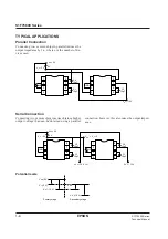
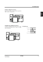
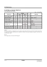
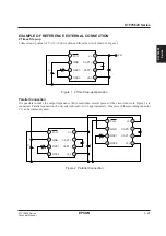
TYPICAL APPLICATIONS
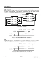
Parallel Connection
Connecting two or more chips in parallel reduces the
output impedance by 1/n, where n is the number of de-
vices used.
5 V
C1
10
µ
F
C2
10
µ
F
V
DD
= 0 V
V
I
= –5 V
V
O
= –10 V
1M
Ω
+
+
8
7
6
5
1
2
3
4
C1
10
µ
F
1M
Ω
+
8
7
6
5
1
2
3
4
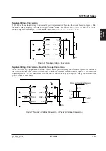
Serial Connection
Connecting two or more chips in series obtains a higher
output voltage than can be obtained using a parallel
connection, however, this also raises the output imped-
ance.
Potential levels
5 V
C1
10
µ
F
C2
10
µ
F
V
DD
= 0 V
V
I
= –5 V
V
O
' = –15 V
V
O
= –10 V = V
I
'
V
DD
' = V
I
= –5
1M
Ω
+
+
8
7
6
5
1
2
3
4
C1
10
µ
F
C2
10
µ
F
1M
Ω
+
+
8
7
6
5
1
2
3
4
V
DD
(0 V)
V
I
(–5 V)
V
O
(–10 V)
Primary stage
Secondary stage
V
DD
'
V
I
'
V
O
' (–15 V)
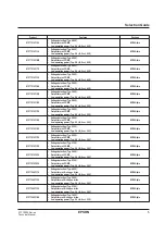
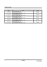
Summary of Contents for S1F76610C0B0
Page 4: ...S1F70000 Series Technical Manual ...
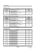
Page 17: ...1 DC DC Converter ...
Page 43: ...2 DC DC Converter Voltage Regulator ...
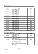
Page 107: ...3 Voltage Regulator ...
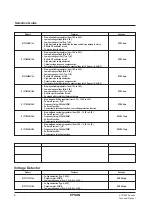
Page 145: ...4 DC DC Switching Regulators ...
Page 200: ...5 Voltage Detector ...
Page 223: ...6 Appendix ...


