


S1F76300 Series
4–20
EPSON
S1F70000 Series
Technical Manual
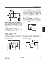
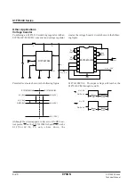
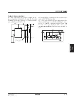
Other Applications
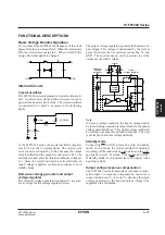
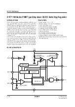
Voltage booster
Combining an S1F76310 switching regulator with an
S1F76610C/M DC/DC converter and voltage regulator
creates the voltage booster circuit shown in the follow-
ing figure.
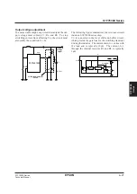
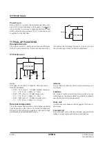
Potential levels are shown in the following figure.
Although the circuit appears to have two ON/OFF con-
trol points, PS on the S1F76310M1A0 and P
OFF
on the
S 1 F 7 6 6 1 0 C / M , P S o n l y s h u t s d o w n t h e
S1F76310M1A0. The input voltage still reaches the
S1F76610C/M through L and D.
C1
C1
10
µ
F
C3
10
µ
F
C2
10
µ
F
+
+
V
O
V
SW
L
D
V
I1
V
I
= –5 V
V
O
= – 15V
R
OSC
1 M
Ω
P
OFF
V
I2
GND
PS
PWCR
S1F76310M
S1F76610C/M
1
2
3
4
5
6
7
14
13
12
11
10
9
8
S1F76610C/M
V
DD
(5 V)
V
DD
(0 V)
V
O
(–10 V)
V
O
(5 V)
V
I
(1.5 V)
GND
(0 V)
S1F76310M1A0
Boost
ON
V
I
= 1.5 V
GND
= 0 V
PS
Boost
OFF
Boost
ON
V
I
= 5 V
GND
= 0 V
P
OFF
Boost
OFF
Summary of Contents for S1F76610C0B0
Page 4: ...S1F70000 Series Technical Manual ...
Page 17: ...1 DC DC Converter ...
Page 43: ...2 DC DC Converter Voltage Regulator ...
Page 107: ...3 Voltage Regulator ...
Page 145: ...4 DC DC Switching Regulators ...
Page 200: ...5 Voltage Detector ...
Page 223: ...6 Appendix ...


