4. Data transfer must be carried out by observing the ACKNLG or
BUSY signal. (Data transfer to this printer can be carried out only
after receipt of the ACKNLG signal or when the level of the BUSY
signal is LOW.)
5. Under normal conditions, printer cable pins
11, 12,
and 32 are acti-
vated when the paper-out condition is detected. The ESCape”8”
code disables pins
11
and 32, but not pin
12.
Those computers that
monitor pin 12 halt printing when the paper is out, making ESCape
“8” ineffective.
Data Transfer Sequence
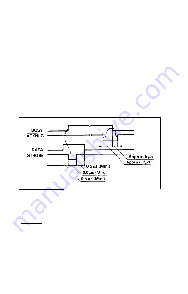
Interface timing
Figure E-1 shows the timing for the parallel interface.
Figure E-1. Parallel interface timing
Printing enabled/disabled signals and control conditions
Table E-2 shows the relationship between printing being enabled or
disabled, and the on-line/off-line condition, the printer select signal
(SLCT IN), and the receipt of data on/off control character,
DC1/DC3.
E-3
Summary of Contents for FX-286 - Impact Printer
Page 1: ......
Page 2: ......
Page 35: ......
Page 40: ...2 4 ...
Page 48: ...3 8 ...
Page 56: ...4 8 ...
Page 91: ...6 16 ...
Page 118: ...C 10 ...
Page 133: ...Epson Mode Commands G 5 ...
Page 134: ...G 6 ...
Page 166: ...H 4 ...
Page 173: ...International Character Width Table Roman characters Italic characters I 7 ...
Page 174: ...I 8 ...
Page 180: ...J 6 ...
Page 181: ...IBM Proprinter Mode Commands J 7 ...
Page 182: ...J 8 ...
Page 202: ...J 28 ...
Page 208: ...K 6 ...
Page 216: ......
Page 220: ...IBM Mode See Appendix J for detailed explanations of codes Character Width Pitch ...
Page 221: ...Notes ...
Page 223: ......


