Epson DFX-9000
Revision B
Operating Principles
Circuit operation
83
SP Motor drive circuit
The SP motor is a DC brushless motor. A dedicated brushless motor
control IC is used to control the speed and position. The position of the
SP motor is controlled using encoder pulse
counts, and the speed is
controlled using Proportional, Integral, Derivative (PID)
and closed-
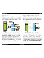
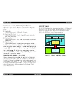
loop control. The following shows a detailed block diagram and timing
chart of the SP motor drive circuit.
Figure 2-27. SP motor drive circuit block diagram
SP motor control signal definitions
CR_C[1:3] is a Hall-effect sensor input signal. When the motor is in
an IN+ > IN- state, the signal is high, and the reverse state is low.
M_CWCCW is a normal/reverse rotation input signal that
determines the direction of the Carrier unit.
M_STSP is a start/stop control signal. When the signal is low, the
motor starts driving. When the signal is high, the motor stops
driving.
M_BRAKE is a brake input signal. When the signal is low, the
motor is braked. When the signal is high, the motor rotates normally.
PWMIN is a pulse input signal (M_TIM1), and its output is
controlled based on the duty levels. When the signal input is low, the
pulse output turns “ON”. When the input is high, the pulse output
turns “OFF”.
UH, UV, UW are PWM output signals that are controlled based on
the duty levels. UH, UV, UW are normally controlled in a saturated
state.
RF is an output current detection terminal. The output current is
determined according to the detected resistance (Iout=0.5/Rf).
PWM frequency is determined according to the capacity of an
external capacitor. It is set to approximately 20 kHz. The frequency
can be determined by calculation using Fpwm=1/(45000*C).
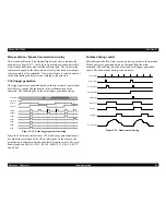
Figure 2-28. Timing Chart
ASIC
Power Unit
M_CWCCW
M_STSP
M_BRAKE
PWMIN
UL
UH
VL
VH
WL
WH
SP MOTOR
Current detection
section
+42V
CR_C[1:3]
(RF)
M_TIM1
SP Motor
Driver
INLK SW ASY
Fuse
(125 V, 8 A)
MOSFET
(U phase)
MOSFET
(V phase)
MOSFET
(W phase)
IN1
IN2
IN3
UH
VH
WH
UL
VL
WL
indicates PWM output.
Summary of Contents for DFX-9000
Page 1: ...EPSONDFX 9000 Serial Impact Dot Matrix Printer SEDM04003 SERVICE MANUAL ...
Page 8: ...C H A P T E R 1 PRODUCT DESCRIPTION ...
Page 61: ...Epson DFX 9000 Revision B Product Description Dimensions and weight 54 ...
Page 62: ...C H A P T E R 2 OPERATING PRINCIPLES ...
Page 99: ...Epson DFX 9000 Revision B Operating Principles Circuit operation 92 ...
Page 100: ...C H A P T E R 3 TROUBLESHOOTING ...
Page 104: ...Epson DFX 9000 Revision B Troubleshooting Overview 97 Mechanism initialization e e e e e ...
Page 107: ...Epson DFX 9000 Revision B Troubleshooting Overview 100 PAPER FEEDING FF APG APPROACH ...
Page 130: ...C H A P T E R 4 DISASSEMBLY AND ASSEMBLY ...
Page 218: ...C H A P T E R 5 ADJUSTMENT ...
Page 263: ...Epson DFX 9000 Revision B Adjustment Additional functions 256 ...
Page 264: ...C H A P T E R 6 MAINTENANCE ...
Page 286: ...C H A P T E R 7 APPENDIX ...
Page 297: ......
Page 298: ......
Page 299: ......
Page 300: ......
Page 301: ......
Page 302: ......
Page 303: ......
Page 304: ......
Page 305: ......
Page 306: ......
Page 307: ......
Page 308: ......
Page 309: ......
Page 310: ......
Page 311: ......
Page 312: ......
Page 313: ......
Page 314: ......
Page 315: ......
Page 316: ......
Page 317: ......
Page 318: ......
Page 319: ......
Page 320: ......
Page 321: ......
Page 322: ......
Page 323: ......
Page 324: ...EPSON DFX 9000 Revision B Appendix Component Layout 317 7 4 Component Layout ...
Page 333: ...EPSON DFX 9000 Revision B Appendix Parts list 326 ...


