Epson DFX-9000
Revision B
Operating Principles
Circuit operation
88
Main excitation / flyback time selection circuitry
This section utilizes an 8-bit Analog/Digital converter to monitor the
head drive voltage (42 V), the 16-byte front main excitation time table,
front flyback time table, and rear flyback time table. The values in the
tables are changed by the firmware on a line-by-line basis according to
the temperature of the printhead. A best control time is selected and sent
to the print timing control section according to the print job.
Print trigger generation
The trigger pulses are generated based on the linear encoder pulse input
for SP motor control and the density value predetermined by the
firmware. The following shows the print trigger generation timing.
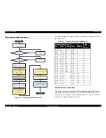
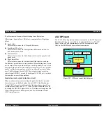
Figure 2-35. Print trigger generation timing
Since the CR encoder resolution is 1/120 inch, some print densities do
not match the resolution of the CR encoder input. In those cases, the
print timing is calculated based on the last CR encoder cycle. The print
density supports 480, 360, 240, 180, 144, 2880/21, 120, 96, 90, 80, 72,
and 60 dpi.
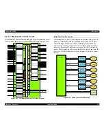
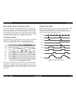
Printhead timing control
After the required offset time is set on a print trigger basis, the main and
flyback pulses are generated based on the input from the main
excitation/ flyback time selection circuit and print trigger generation
circuit. The head control timing is shown below.
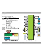
Figure 2-36. Head control timing
CLK(24M)
TRIGEN
Phase A
Phase B
480dpi
240dpi
120dpi
96dpi
80dpi
60dpi
48dpi
Print Trigger
Current Signal
Offset Timer
Parallel Timer
Parellel Enable
Mask Signal
MFTIM_11
MAINF_11
FLYBK_11
Summary of Contents for DFX-9000
Page 1: ...EPSONDFX 9000 Serial Impact Dot Matrix Printer SEDM04003 SERVICE MANUAL ...
Page 8: ...C H A P T E R 1 PRODUCT DESCRIPTION ...
Page 61: ...Epson DFX 9000 Revision B Product Description Dimensions and weight 54 ...
Page 62: ...C H A P T E R 2 OPERATING PRINCIPLES ...
Page 99: ...Epson DFX 9000 Revision B Operating Principles Circuit operation 92 ...
Page 100: ...C H A P T E R 3 TROUBLESHOOTING ...
Page 104: ...Epson DFX 9000 Revision B Troubleshooting Overview 97 Mechanism initialization e e e e e ...
Page 107: ...Epson DFX 9000 Revision B Troubleshooting Overview 100 PAPER FEEDING FF APG APPROACH ...
Page 130: ...C H A P T E R 4 DISASSEMBLY AND ASSEMBLY ...
Page 218: ...C H A P T E R 5 ADJUSTMENT ...
Page 263: ...Epson DFX 9000 Revision B Adjustment Additional functions 256 ...
Page 264: ...C H A P T E R 6 MAINTENANCE ...
Page 286: ...C H A P T E R 7 APPENDIX ...
Page 297: ......
Page 298: ......
Page 299: ......
Page 300: ......
Page 301: ......
Page 302: ......
Page 303: ......
Page 304: ......
Page 305: ......
Page 306: ......
Page 307: ......
Page 308: ......
Page 309: ......
Page 310: ......
Page 311: ......
Page 312: ......
Page 313: ......
Page 314: ......
Page 315: ......
Page 316: ......
Page 317: ......
Page 318: ......
Page 319: ......
Page 320: ......
Page 321: ......
Page 322: ......
Page 323: ......
Page 324: ...EPSON DFX 9000 Revision B Appendix Component Layout 317 7 4 Component Layout ...
Page 333: ...EPSON DFX 9000 Revision B Appendix Parts list 326 ...

