Epson DFX 9000
Revision B
Disassembly and Assembly
SP MOTOR ASY
156
4.2.4.4 SP MOTOR ASY
1. Remove the
UPPER UNIT (p. 135)
2. Tilt up the rear of the PR MECHA ASY and support it using the tilt
bar.
Refer to section 4.2.4.1 PR MECHA ASY, p. 149.
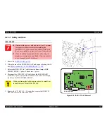
3. Disconnect the SP MOTOR ASY cable from the connectors on the
ROM BOARD (CNSPM: 3 pins, CNSPHS: 7 pins). See
Figure 4-31
.
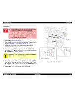
4. Release the SP MOTOR ASY cable from the cable clamp on the
bottom rear of the printer, and pull the cable out through the hole in
the SIDE FRAME, RIGHT.
5. Remove the two C.B.S. 3 × 6 screws that secure the FAN3 MOTOR,
and remove it.
6. Remove the two C.B.S. 3 × 8 screws that secure the Stopper BR to
the SIDE FRAME, RIGHT, and remove the Stopper BR.
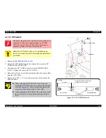
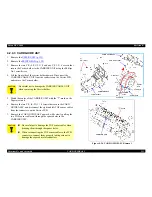
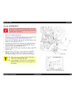
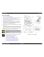
Figure 4-31. SP MOTOR ASY connectors on the ROM BOARD
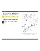
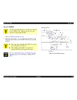
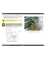
Figure 4-32. SP MOTOR ASY Removal (1)
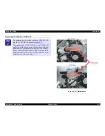
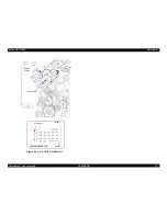
Figure 4-33. SP MOTOR ASY Removal (2)
7. Remove the three C.P. (S-P1) 4 × 10 screws that secure the SP
MOTOR ASY to the bracket of the SIDE FRAME, RIGHT.
W A R N I N G
Do not touch the SP MOTOR ASY immediately after
using the printer, or you may burn your hand. Allow the
motor assembly to cool enough to work with it.
CNSPHS
CNSPM
5)
5)
FAN3 MOTOR
SP MOTOR ASY
6)
Stopper BR
Summary of Contents for DFX-9000
Page 1: ...EPSONDFX 9000 Serial Impact Dot Matrix Printer SEDM04003 SERVICE MANUAL ...
Page 8: ...C H A P T E R 1 PRODUCT DESCRIPTION ...
Page 61: ...Epson DFX 9000 Revision B Product Description Dimensions and weight 54 ...
Page 62: ...C H A P T E R 2 OPERATING PRINCIPLES ...
Page 99: ...Epson DFX 9000 Revision B Operating Principles Circuit operation 92 ...
Page 100: ...C H A P T E R 3 TROUBLESHOOTING ...
Page 104: ...Epson DFX 9000 Revision B Troubleshooting Overview 97 Mechanism initialization e e e e e ...
Page 107: ...Epson DFX 9000 Revision B Troubleshooting Overview 100 PAPER FEEDING FF APG APPROACH ...
Page 130: ...C H A P T E R 4 DISASSEMBLY AND ASSEMBLY ...
Page 218: ...C H A P T E R 5 ADJUSTMENT ...
Page 263: ...Epson DFX 9000 Revision B Adjustment Additional functions 256 ...
Page 264: ...C H A P T E R 6 MAINTENANCE ...
Page 286: ...C H A P T E R 7 APPENDIX ...
Page 297: ......
Page 298: ......
Page 299: ......
Page 300: ......
Page 301: ......
Page 302: ......
Page 303: ......
Page 304: ......
Page 305: ......
Page 306: ......
Page 307: ......
Page 308: ......
Page 309: ......
Page 310: ......
Page 311: ......
Page 312: ......
Page 313: ......
Page 314: ......
Page 315: ......
Page 316: ......
Page 317: ......
Page 318: ......
Page 319: ......
Page 320: ......
Page 321: ......
Page 322: ......
Page 323: ......
Page 324: ...EPSON DFX 9000 Revision B Appendix Component Layout 317 7 4 Component Layout ...
Page 333: ...EPSON DFX 9000 Revision B Appendix Parts list 326 ...


