About This Manual
This manual describes basic functions, theory of electrical and mechanical operations, maintenance and repair procedures of the printer. The instructions and
procedures included herein are intended for the experienced repair technicians, and attention should be given to the precautions on the preceding page.
Manual Configuration
This manual consists of six chapters and Appendix.
CHAPTER 1. PRODUCT DESCRIPTIONS
Provides a general overview and specifications of the
product.
CHAPTER 2. OPERATING PRINCIPLES
Describes the theory of electrical and mechanical
operations of the product.
CHAPTER 3. TROUBLESHOOTING
Describes the step-by-step procedures for the
troubleshooting.
CHAPTER 4. DISASSEMBLY / ASSEMBLY
Describes the step-by-step procedures for disassembling
and assembling the product.
CHAPTER 5. ADJUSTMENT
Provides Epson-approved methods for adjustment.
CHAPTER 6. MAINTENANCE
Provides preventive maintenance procedures and the
lists of Epson-approved lubricants and adhesives
required for servicing the product.
APPENDIX
Provides the following additional information for
reference:
• Connector pin assignments
• Electric circuit boards components layout
• Electrical circuit boards schematics
• Exploded diagram & Parts List
Symbols Used in this Manual
Various symbols are used throughout this manual either to provide
additional information on a specific topic or to warn of possible danger
present during a procedure or an action. Be aware of all symbols when
they are used, and always read NOTE, CAUTION, or WARNING
messages.
Indicates an operating or maintenance procedure, practice
or condition that is necessary to keep the product’s quality.
Indicates an operating or maintenance procedure, practice,
or condition that, if not strictly observed, could result in
damage to, or destruction of, equipment.
May indicate an operating or maintenance procedure,
practice or condition that is necessary to accomplish a task
efficiently. It may also provide additional information that is
related to a specific subject, or comment on the results
achieved through a previous action.
Indicates an operating or maintenance procedure, practice
or condition that, if not strictly observed, could result in injury
or loss of life.
Indicates that a particular task must be carried out
according to a certain standard after disassembly and
before re-assembly, otherwise the quality of the
components in question may be adversely affected.
A D J U S T M E N T
R E Q U I R E D
C A U T I O N
C H E C K
P O I N T
W A R N I N G
Summary of Contents for DFX-9000
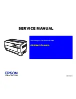
Page 1: ...EPSONDFX 9000 Serial Impact Dot Matrix Printer SEDM04003 SERVICE MANUAL ...
Page 8: ...C H A P T E R 1 PRODUCT DESCRIPTION ...
Page 61: ...Epson DFX 9000 Revision B Product Description Dimensions and weight 54 ...
Page 62: ...C H A P T E R 2 OPERATING PRINCIPLES ...
Page 99: ...Epson DFX 9000 Revision B Operating Principles Circuit operation 92 ...
Page 100: ...C H A P T E R 3 TROUBLESHOOTING ...
Page 104: ...Epson DFX 9000 Revision B Troubleshooting Overview 97 Mechanism initialization e e e e e ...
Page 107: ...Epson DFX 9000 Revision B Troubleshooting Overview 100 PAPER FEEDING FF APG APPROACH ...
Page 130: ...C H A P T E R 4 DISASSEMBLY AND ASSEMBLY ...
Page 218: ...C H A P T E R 5 ADJUSTMENT ...
Page 263: ...Epson DFX 9000 Revision B Adjustment Additional functions 256 ...
Page 264: ...C H A P T E R 6 MAINTENANCE ...
Page 286: ...C H A P T E R 7 APPENDIX ...
Page 297: ......
Page 298: ......
Page 299: ......
Page 300: ......
Page 301: ......
Page 302: ......
Page 303: ......
Page 304: ......
Page 305: ......
Page 306: ......
Page 307: ......
Page 308: ......
Page 309: ......
Page 310: ......
Page 311: ......
Page 312: ......
Page 313: ......
Page 314: ......
Page 315: ......
Page 316: ......
Page 317: ......
Page 318: ......
Page 319: ......
Page 320: ......
Page 321: ......
Page 322: ......
Page 323: ......
Page 324: ...EPSON DFX 9000 Revision B Appendix Component Layout 317 7 4 Component Layout ...
Page 333: ...EPSON DFX 9000 Revision B Appendix Parts list 326 ...

