Epson DFX 9000
Revision B
Disassembly and Assembly
OP CABLE
144
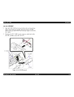
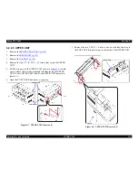
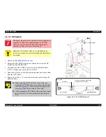
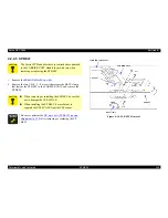
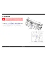
4.2.3.5 OP CABLE
1. Remove the
PR MECHA ASY (p. 149)
.
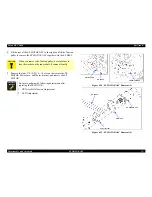
2. Release the OP CABLE from the two clamps that secure the OP
CABLE to the LOWER UNIT.
3. Disconnect the OP CABLE connector from the ROM BOARD
(CNOP: 10 pins), and remove the OP CABLE.
4. Open the two ferrite cores at their partition points, and remove them
from the OP CABLE.
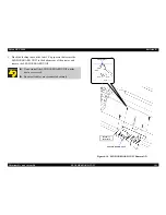
5. Remove the C.B.S. 3 × 8 screw that secures the cable clamp to the
right side frame.
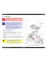
Figure 4-18. OP CABLE Removal
W A R N I N G
Disconnect the power cable and wait at least 5 minutes for
capacitors to drain before disassembling the POWER
UNIT. If you touch the POWER UNIT with the power
supplied, you may receive an electric shock.
C A U T I O N
Handle the OP CABLE with care. It is shielded, and a
ferrite core is attached to it for electromagnetic interference
prevention.
When replacing the OP CABLE, wrap cotton tape
around the OP CABLE five or six times in the position
shown in
Figure 4-18
. This will help the upper ferrite
core stay in the correct position on the cable.
After wrapping the OP CABLE with cotton tape, install
the two ferrite cores in the positions shown in Figure
4-18.
2)
3)-1
OP CABLE
Ferrite Cores
OP UNIT Side
ROM BOARD Side
4)-1
Reassembly
85 ± 5 mm
Cotton Tape, 10 mm (1/2 inch) wide
Wind the tape 5 or 6 times.
5)
Cable clamp
Summary of Contents for DFX-9000
Page 1: ...EPSONDFX 9000 Serial Impact Dot Matrix Printer SEDM04003 SERVICE MANUAL ...
Page 8: ...C H A P T E R 1 PRODUCT DESCRIPTION ...
Page 61: ...Epson DFX 9000 Revision B Product Description Dimensions and weight 54 ...
Page 62: ...C H A P T E R 2 OPERATING PRINCIPLES ...
Page 99: ...Epson DFX 9000 Revision B Operating Principles Circuit operation 92 ...
Page 100: ...C H A P T E R 3 TROUBLESHOOTING ...
Page 104: ...Epson DFX 9000 Revision B Troubleshooting Overview 97 Mechanism initialization e e e e e ...
Page 107: ...Epson DFX 9000 Revision B Troubleshooting Overview 100 PAPER FEEDING FF APG APPROACH ...
Page 130: ...C H A P T E R 4 DISASSEMBLY AND ASSEMBLY ...
Page 218: ...C H A P T E R 5 ADJUSTMENT ...
Page 263: ...Epson DFX 9000 Revision B Adjustment Additional functions 256 ...
Page 264: ...C H A P T E R 6 MAINTENANCE ...
Page 286: ...C H A P T E R 7 APPENDIX ...
Page 297: ......
Page 298: ......
Page 299: ......
Page 300: ......
Page 301: ......
Page 302: ......
Page 303: ......
Page 304: ......
Page 305: ......
Page 306: ......
Page 307: ......
Page 308: ......
Page 309: ......
Page 310: ......
Page 311: ......
Page 312: ......
Page 313: ......
Page 314: ......
Page 315: ......
Page 316: ......
Page 317: ......
Page 318: ......
Page 319: ......
Page 320: ......
Page 321: ......
Page 322: ......
Page 323: ......
Page 324: ...EPSON DFX 9000 Revision B Appendix Component Layout 317 7 4 Component Layout ...
Page 333: ...EPSON DFX 9000 Revision B Appendix Parts list 326 ...

