


95
CTC EcoLogic Pro/Family
For the installer
9.2.5
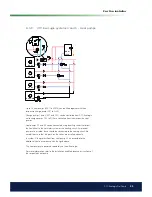
CTC EcoLogic systems 2 and 3 – Cooling
If the Cooling function is deined, mixing valve Y3, charge pump G3 and
sensor B3 should be used for the cooling installation (not heating circuit
3). For details on how to connect, see the Installation and Maintenance
instructions for the cooling installation.
Fan convector
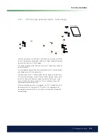
From the solar panels, the heat low is directed to the hot water tank/buffer
tank or to the ground heating loop in order to recharge the bedrock/ground
once the hot water tank is fully charged.
The speed-controlled pump (G30) and sensors B31 and B30 are itted next
to the solar panels.
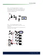
For recharging the bedrock/ground, a diverting valve (Y31), heat exchanger
and charge pump (G31) are connected.
The diverting valve (Y31) is itted together with the speed-controlled pump
(G32) and heat exchanger in order to direct the low towards the hot water
tank or the buffer tank. Heat exchangers and pumps (G32) do not need
to be installed to the solar heating circuit if there is already a loop in the
connected hot water/heating tank.
When the recharging function is in operation, the CTC EcoLogic also starts
the brine pump in the heat pump (CTC EcoPart). The charge pump for
recharging the bore hole (G31) ensures there is suficient low through the
heat exchanger.
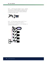
9.2.6
CTC EcoLogic systems 2 and 3 – Solar energy
Solar panels
Summary of Contents for CTC EcoLogic Family series
Page 2: ......
Page 3: ...162 105 48 3 2016 04 08 Installation and Maintenance Manual CTC EcoLogic Pro Family...
Page 67: ...67 CTC EcoLogic Pro Family For the property owner...
Page 120: ...120 CTC EcoLogic Pro Family For the installer 11 Wiring diagram...
Page 121: ...121 CTC EcoLogic Pro Family For the installer...
Page 127: ......