


89
CTC EcoLogic Pro/Family
For the installer
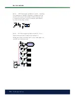
The coniguration of EcoLogic systems 2 and 3 differ in terms of the location
of the additional heat source.
EcoLogic
system 2
In EcoLogic system 2, the additional heat is located
before
the hot water
system, while in EcoLogic system 3 it is located after the hot water system.
Heat pumps A1 and A2 can be connected using diverting valves that direct
the low either to the hot water system or the heating circuit. If more heat
pumps are installed, these should be connected to the heating circuit.
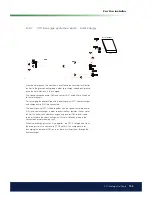
When connecting the buffer tank, the mixing valve (Y4) is used to connect
the tank to the system (not to heating circuit 4).
Solar energy can be connected either to the hot water tank or to the buffer
tank using diverting valves. The solar energy can also be used to recharge
the bedrock/ground.
Cooling can easily be connected to the bedrock/ground source heating
system.
+
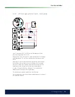
9.2
CTC EcoLogic systems 2 and 3*
Heating circuit 4
Heating circuit 3
Heating circuit 2
Heating circuit 1
Fan convector
Solar panels
Additional heat
Hot water system
Cooling
Buffer tank
HP A1
HP A2
HP A3 - A10
DHW
tank
Brine circuit
*
The CTC EcoLogic Fam-
ily, systems 2 and 3, do
not include the following
subsystems and their as-
sociated pumps, valves
and sensors:
-Heat pumps 3 to 10
-Heating circuits 3 and 4
-Cooling
-Recharging bedrock
-Solar energy
-Hot water circ. (DHW
CIRC.)
-External hot water tank
-Buffer tank
Summary of Contents for CTC EcoLogic Family series
Page 2: ......
Page 3: ...162 105 48 3 2016 04 08 Installation and Maintenance Manual CTC EcoLogic Pro Family...
Page 67: ...67 CTC EcoLogic Pro Family For the property owner...
Page 120: ...120 CTC EcoLogic Pro Family For the installer 11 Wiring diagram...
Page 121: ...121 CTC EcoLogic Pro Family For the installer...
Page 127: ......