


116
CTC EcoLogic Pro/Family
For the installer
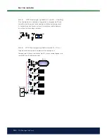
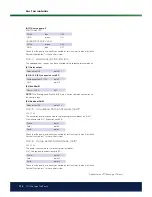
10.2.9.2 Charge pump – recharging bore hole (G31)*
230 V 1N~
The charge pump is connected at the following terminal blocks:
(G31) Charge pump, expansion card (X6):
Phase:
pole 8
also controls Diverting valve –
solar (Y31)
Zero:
pole 11
Earth:
pole 10
Pole 8 is connected to an external connection box which distributes voltage to
the solar diverting valve (Y31) and the Recharge Bore Hole charge pump (G31).
Refer to the wiring diagram.
Check the function by test running the pump in menu
“Installer/Service/Function
test”.
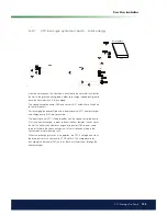
10.2.10 Pool pumps (G50) and (G51)
230 V 1N~
Both pumps (G50) & (G51) are connected to the following terminal blocks:
Pumps pool (G50) and (G51), expansion card X7:
Phase:
pole 33
Zero:
pole 35
Earth:
pole 34
Pole 33 is connected to an external connection box which distributes voltage to
the charge pump (G50) and circulation pump (G51).
Check the function by test running the pump in menu
“Installer/Service/Function
test” in the control system.
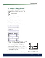
10.3
Protection - low voltage (sensor)
The sensors that form part of each system solution (schematic diagrams 1
to 6) should be itted to the PCB/terminal block as follows: All sensors are
temperature sensors.
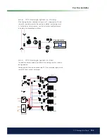
10.3.1
Room sensors (B11, B12, B13, B14)
Room sensor cable connection:
(B11) Room sensor 1
block no.
G17
alarm output
block no.
G18
GND
block no.
G19
input
(B12) Room sensor 2
block no.
G20
alarm output
block no.
G21
GND
block no.
G22
input
(B13) Room sensor 3, expansion card X4*
block no.
19
alarm output
block no.
20
input
block no.
21
GND
*Applies to the CTC EcoLogic PRO only.
Summary of Contents for CTC EcoLogic Family series
Page 2: ......
Page 3: ...162 105 48 3 2016 04 08 Installation and Maintenance Manual CTC EcoLogic Pro Family...
Page 67: ...67 CTC EcoLogic Pro Family For the property owner...
Page 120: ...120 CTC EcoLogic Pro Family For the installer 11 Wiring diagram...
Page 121: ...121 CTC EcoLogic Pro Family For the installer...
Page 127: ......