


117
CTC EcoLogic Pro/Family
For the installer
(B14) Room sensor 4, expansion card X4*
block no.
22
alarm output
block no.
23
input
block no.
24
GND
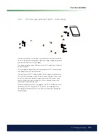
Room sensors should be installed at head height in open areas of the
property with good air low and where a representative temperature can
be expected (not close to sources of heat or cold). Place sensors at head
height. If you are unsure of where to place a sensor, hang it by a loose cable
and test different positions.
Connection: 3-conductor cable, min. 0.5 mm², between sensor and control
box. The cables are connected as shown in the table above.
On start-up, an alarm is given if the sensor is incorrectly connected. Test the
alarm sensor LED by testing the function in menu
Installer/Service/Function
test.
In the control system you can select whether or not to have the room sensor
operational. If the room sensor is deselected, the heating level is controlled
by the outdoor sensor/primary low sensor. The alarm lamp on the room
sensor still functions as normal. A room sensor does not, however, need to
be installed if the function is deselected.
10.3.2 Outdoor sensor (B15)
The outdoor sensor should be itted to the outer wall of the house, preferably
in a north-northeastern or north-northwestern direction. The sensor should
be placed out of direct sunlight. However, where this is dificult to achieve it
can also be shielded from the sun by a screen. Remember that the sun rises
and sets at different points at different times of the year.
The sensor should be placed about three-quarters of the way up the wall so
that it senses the correct outdoor temperature and so that it is not affected
by a heat source such as a window, infra-heating, air ventilation outlet, etc.
Connection: 2-conductor cable (min. 0.5 mm²) between the sensor and
control box.
The sensor is connected to terminal blocks G11 and G12 of the control
module. Connect to the outdoor sensor at the arrows.
NOTE!
Strip the wire ends and fold them double if light cable is used.
It is important that the contact in the connections is good.
Sensor connections
Mount the sensor on the pipe. The sensing part is towards the end of the
sensor.
• Attach the sensor using the tie strap provided.
• Ensure that the sensor makes good contact with the pipe.
• Apply contact paste to the end part of the sensor between the sensor
and the pipe if good contact is otherwise dificult to obtain.
•
NOTE!
Insulate the sensor using pipe insulation, for example. This
prevents the measurement from being affected by the ambient
temperature.
• Connect the cables to the CTC EcoLogic’s connection block. If the
cable is too short, join extra length to it.
*Applies to the CTC EcoLogic PRO only.
Summary of Contents for CTC EcoLogic Family series
Page 2: ......
Page 3: ...162 105 48 3 2016 04 08 Installation and Maintenance Manual CTC EcoLogic Pro Family...
Page 67: ...67 CTC EcoLogic Pro Family For the property owner...
Page 120: ...120 CTC EcoLogic Pro Family For the installer 11 Wiring diagram...
Page 121: ...121 CTC EcoLogic Pro Family For the installer...
Page 127: ......