15
Manual Supplement
00809-0300-4570, Rev BA
Rosemount 5708 Series 3D Solids Scanner Integration with DeltaV
2016
Rosemount 5708 Series 3D Solids Scanner Integration with DeltaV
2.0
Configuring byte order for connection via serial card
Modbus
®
is an application layer messaging protocol, positioned at level 7 of the OSI model, which
provides client/server communication between devices connected on different types of buses or
networks.
Modbus bases its data model on a series of tables that have distinguishing characteristics
http://www.Modbus.org
The four primary tables are:
Since floating points and long integers (32-bit) are not embedded in Modbus, different methods have
been used to send and receive data. The most common used method for the transfer of extended data
types (floating point and long integers) is two consecutive 16-bit registers; however, the transmission
sequence of the registers is not fixed.
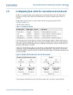
The Rosemount 5708 3DLevel device sends the Most–Significant Bit (MSB) in the first Modbus register
and the Less–Significant Bit (LSB) in the following register. Nevertheless, when DeltaV is set to read a
32-bit data register, it assigns the 16-bit world in the first Modbus register to the LSB data and the second
register to the MSB.
The discrepancy described above shows that the parameter data is not read correctly by DeltaV.
Table 1-3. Modbus Data Model
Primary tables
Object type
Type of
Comments
Discrete Input
Single bit
Read-Only
Can be provided by an I/O system
Coils
Single bit
Read-Write
Can be alterable by an application program
Input registers
16-bit word
Read-Only
Can be provided by an I/O system
Holding Registers
16-bit word
Read-Write
Can be alterable by an application program
Figure 1-6. Modbus Word Order in Rosemount 5708 and DeltaV
Rosemount 5708 3D Solids Scanner
DeltaV
MSB
LSB
MSB
LSB
16-bit word
16-bit word
16-bit word
16-bit word
Register Low
(4000X)
Register High
(4000X+1)
Register Low
(4000X)
Register High
(4000X+1)
16-bit word
16-bit word
16-bit word
16-bit word
Modbus Data
Modbus Data

