background image

11

Manual Supplement 

00809-0300-4570, Rev BA

Rosemount 5708 Series 3D Solids Scanner Integration with DeltaV

2016

Rosemount 5708 Series 3D Solids Scanner Integration with DeltaV

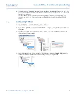
13. Select 

OK

.

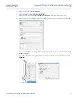
14. Right-click on the port which was just enabled and select 

New Serial device

. This device will 

represent the 3D Solids Scanner device. The 

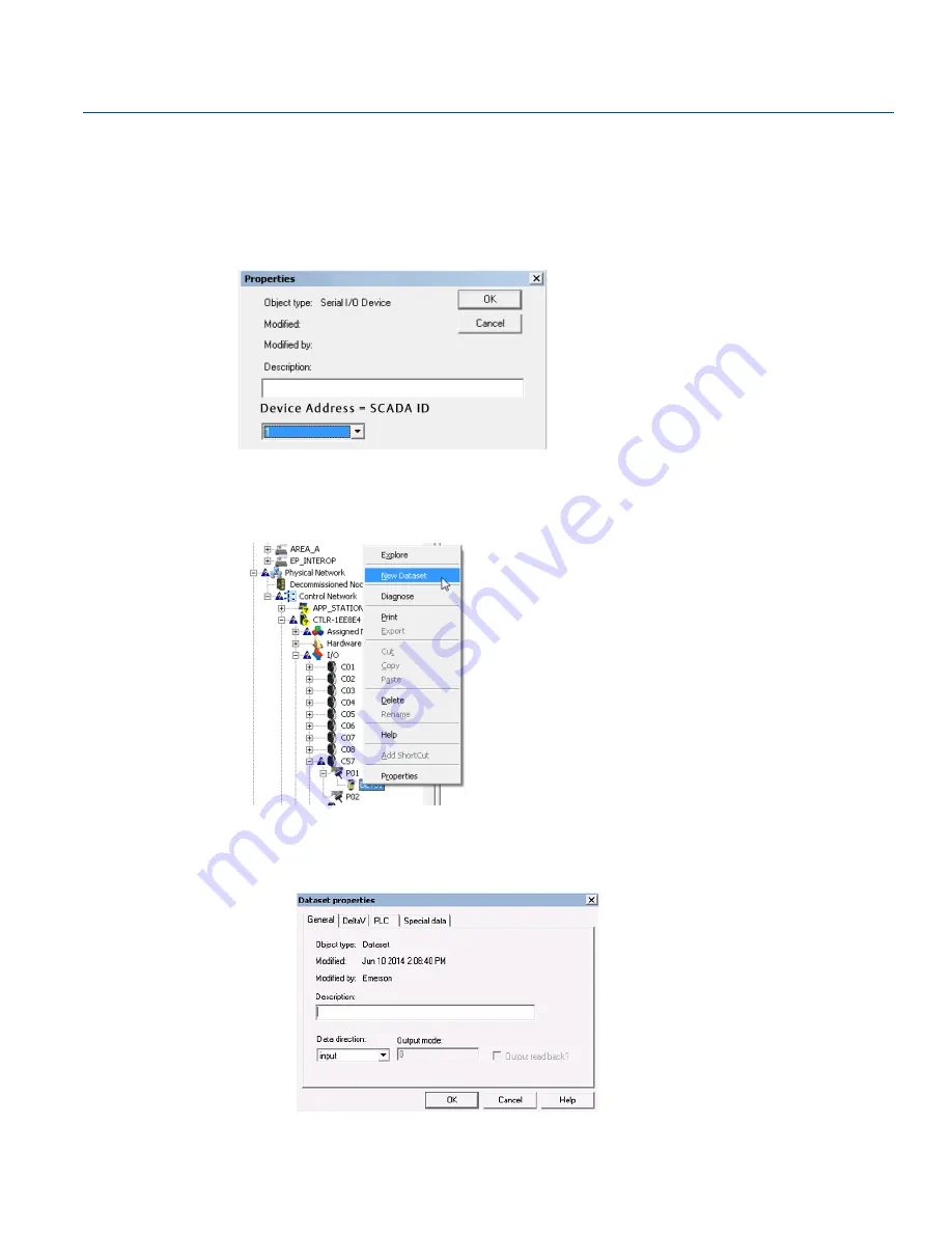
Properties

 window opens.

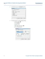
15. In the 

Properties

 window, enter any desired Description and the Device Address. The Device Address 

will be the 3D Solids Scanner's SCADA ID. Select 

OK

 when finished. 

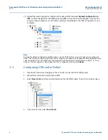
16. Expand the port with the newly added device.

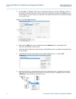
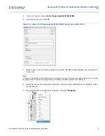
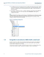
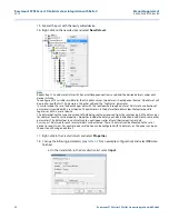
17. Right-click on the new device and select 

New Dataset

, see figure below.

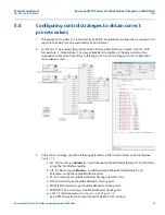
Add a new dataset to the device.

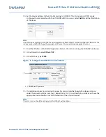
18. In the 

Dataset properties


window, change the following parameters and select 

OK

 when finished. See 

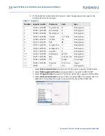
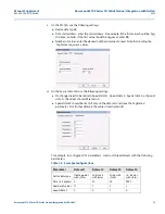
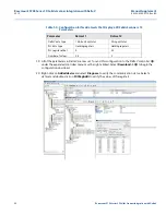
Table 1-2

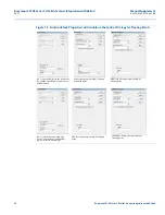
 for an example configuration which displays all 13 parameters.

a. On the 

General

 tab, in the 

Data direction

 list, select 

input

.

Summary of Contents for Rosemount 5708 3D Solids Scanner DeltaV Series

Page 1: ...g up 3DVison in DeltaV operate screen page 27 1 0 Introduction This document indicates how to setup and configure Rosemount 5708 3D Solids Scanner with DeltaV using two different methods Configuration details are included for the physical network DeltaV Explorer 3DMultiVision Client and VIMNet The VIMNet application interfaces with the VIM card a necessary component for one of the setups which Del...

Page 2: ...ation and control by DeltaV The application station will be able to use the 3DMultiVision software to setup the 3D Solids Scanner show detail curves and monitor values 2 0 Specifications The configuration presented here has been verified with the following specifications DeltaV supported version is 12 3 and above Required support of Microsoft NET Framework 4 0 VIMNet version 9 1 15 1 VIM version 3...

Page 3: ...The DeltaV Application Station will be the station running the 3DMultiVision software 2 Setup another separate network switch connected to the VIM card the DeltaV Application Station running 3DMultiVision and the 3D Solids Scanner Note The 3D Solids Scanner uses a serial communication link to the network An RS485 to TCP IP converter is required to connect the device to the network switch An RS485 ...

Page 4: ...ools Server Options SCADA Configuration Port The Port stands for a TCP Port that is available to use in the network please consult with local IT for available TCP ports Make sure that there are no other systems like firewalls antivirus and others that prevent the communication using the selected port Type Type stands for the Modbus communication type it can be either Modbus TCP or Modbus RTU make ...

Page 5: ...dware inventory table in 3DVision go to Tools Reports Hardware Inventory Table The Vessel ID appears in the right most column under the SCADA ID header 3 2 Configuring VIMNet 1 Open VIMNet Explorer on the DeltaV Application Station 2 Right click on I O Net and select New Controller This will open a prompt for the name of the new controller 3 Type the name of the new controller The name of the new ...

Page 6: ...Figure 1 2 Set the VIM Properties A Any available IP will work B Subnet mask set to match network C Check IP availability here 6 Right click the VIM which was just added and select Commission A list will populate with Decommissioned VIMs on the network 7 Select the desired VIM to be commissioned an Identify VIM function is available in the bottom right of the window 8 Check that the IP Address fie...

Page 7: ...is done to allow the DeltaV to get the complete data from of the vessel and not independent scanner 11 Enter the IP Address of the DeltaV Application Station the station running the 3DMultiVision Server 12 In the Protocol list select RTU via TCP 13 In the Port box type 12345 Figure 1 3 Configure the IP Definition for the Device A 3DMultiVision PC goes here 14 If a multidrop connection is desired t...

Page 8: ...figuration to VIM routine is run the 3DMultiVision server will stop communicating with DeltaV The server must be restarted or the SCADA Configuration window must be opened and acknowledged to see values on DeltaV The SCADA Definition can be found in the 3DMultiVision Client application under Tools Server Options SCADA Configuration Simply open the SCADA Configuration tab and select Apply 3 3 Confi...

Page 9: ...l Card on Slots 57 60 7 Repeat steps 3 and 4 for Slot position 58 59 and 60 The VIM module emulates four serial cards in slots 57 60 Note Cards can also be added via the DeltaV Explorer using the Auto sense I O cards menu option All four cards must be configured even if you are not using all of them In addition disable all unused serial card ports 8 Select the same serial card and port which was u...

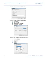
Page 10: ...D Solids Scanner Integration with DeltaV 10 On the Port tab select the Enabled check box 11 On the Advanced tab use the following settings Mode master Retry count 10 Message timeout ms 10000 Transmit delay ms 2000 12 On the Communications tab use the following settings Port type RS232 Baud rate 115200 Parity even Data bits 8 Stop bits 1 ...

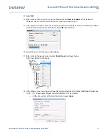
Page 11: ...ns 15 In the Properties window enter any desired Description and the Device Address The Device Address will be the 3D Solids Scanner s SCADA ID Select OK when finished 16 Expand the port with the newly added device 17 Right click on the new device and select New Dataset see figure below Add a new dataset to the device 18 In the Dataset properties window change the following parameters and select O...

Page 12: ...49990 This register does not deliver data but polling this register is required for creation of the 3D data files Table 1 1 Registers Number Register number Parameter Units Type 1 40001 and 40002 Avg distance m Floating point 2 40003 and 40004 Min distance m Floating point 3 40005 and 40006 Max distance m Floating point 4 40007 and 40008 Volume 1000 Floating point 5 40009 and 40010 4 20mA mA Float...

Page 13: ... values d On the Special data tab use the following settings No changes need to be made to Special data 1 Special data 3 Special data 4 or Special data 5 the values should all remain 0 Special data 2 should be set to 1 only on the dataset to retrieve the Tag Name parameter For all other datasets the value should remain 0 For example to configure all 13 parameters construct three datasets with the ...

Page 14: ...e a download to the controller or any of the cards occurs the 3DMultiVision server will stop communicating with DeltaV The server must be restarted or the SCADA Definition window must be opened and OK d to see values on DeltaV The SCADA Definition can be found in the 3DVision application under Tools Server Options SCADA Configuration Open the SCADA Definition and select OK Figure 1 5 Download the ...

Page 15: ... The Rosemount 5708 3DLevel device sends the Most Significant Bit MSB in the first Modbus register and the Less Significant Bit LSB in the following register Nevertheless when DeltaV is set to read a 32 bit data register it assigns the 16 bit world in the first Modbus register to the LSB data and the second register to the MSB The discrepancy described above shows that the parameter data is not re...

Page 16: ...ids Scanner 2 Once the byte order has been swapped the floating point parameters are converted from binary to IEEE 754 floating point using the following math equation IEEE 754 1 Sign 1 Mantissa 2 Exponent 127 3 Once the byte order has been swapped the long integer parameters can be retrieved by converting from binary to decimal 4 0 Configuring serial card in DeltaV 1 Open DeltaV Explorer and navi...

Page 17: ...t 2 Ports RS232 RS485 In the Card series list select Series 2 for M series hardware For S series there is no choice 6 In the Slot position list select the slot position where the new serial card is attached and select OK Once a serial card has been configured the serial port properties can be set and serial devices can be added to the ports 7 Expand the added serial card right click the port where...

Page 18: ...nner Integration with DeltaV 2016 Rosemount 5708 Series 3D Solids Scanner Integration with DeltaV 8 On the Port tab select the Enabled check box 9 On the Advanced tab use the following settings Protocol type RTU Mode Master Retry count 1 Message timeout ms 1000 Transmit delay ms 0 ...

Page 19: ...rameters 11 Select the port of the serial card PO1 or PO2 where the 3D Solids Scanner is connected and where the communication parameters were set in the above steps 12 Right click and select New Serial device 13 Set the device address to match the address of the physical 3D Solids Scanner connected to the serial card The Device Address will be the 3D Solids Scanner s Polling Address 1 14 If a mul...

Page 20: ...d with a serial device The parameters in the dataset hold data values that correspond to registers or data in a serial device The dataset defines the type and amount of data being sent to or received from the serial device All the data values for a dataset have the same properties Properties include the data type and data direction in addition to some other parameters The data values in a dataset ...

Page 21: ...rred as Dataset2 c On the PLC tab use the following settings i PLC data type holding registers apply for both Datasets properties ii PLC register offset Enter the start address For example if the first value should be Avg Distance enter 0 If the first value should be Avg Level enter 16 iii Number of values Enter the desired number of values to read Note that to read each parameter Avg Distance Min...

Page 22: ...st be right clicked Select Download I O to begin the configuration download 20 Right click on Added device and select Diagnose to verify the communication status Select a dataset and double click on StrtRegAddr to verify the values of the registers Table 1 4 Configuration for Two Datasets that Display a 3D Solids Scanner s 13 Parameters Parameter Dataset 1 Dataset 2 DeltaV data type 16 bit unit w ...

Page 23: ...ary to floating point A control strategy with the configuration shown below is used 3 In the control strategy set up the following parameters in the function blocks and variables see Figure 1 7 a AI1 For Device Tag use Browse to add the newly defined Dataset Dataset1 For Parameter assign the first Modbus register b AI2 For Device Tag use Browse to add the newly defined Dataset Dataset1 For Paramet...

Page 24: ... Control Strategy for Floating Points AI2 Set up the Dataset in the filed Device Tag and the second Modbus register in the field Parameter SING Parameter type should be Floating point EXPONENT Parameter type should be Floating point AI1 Set up the Dataset in the filed Device Tag and the first Modbus register in the field Parameter PV Parameter type should be Floating point with status MANTISSA Par...

Page 25: ... Solids Scanner Integration with DeltaV Figure 1 8 Expression in CALC Block Control Strategy for Floating Points 4 For the parameter SN Serial Number the byte order must be swapped and converted from binary to long integer A control strategy with the configuration shown in Figure 1 9 was used Figure 1 9 Control Strategy for Long Integers ...

Page 26: ...he newly defined Dataset Dataset1 For Parameter assign the second Modbus register 40024 c PV Parameter type should be defined as 32 bit unsigned integer d CALC1 Enter the expression as shown in Figure 1 11 Figure 1 10 Properties for Function Blocks and Variables in the Control Strategy for Long Integers Figure 1 11 Expression in CALC Block Control Strategy for Long Integers AI1 Set up the Dataset ...

Page 27: ...s register 49990 in the 5708 3DVision server software is being read via Modbus Check if enc files do exist in the 3D image folder on the Application station example c 3Dvision and getting updated The 5708 3DVision server software has been installed and configured On the Application station share drive c to everyone read Microsoft NET Framework 4 0 has been installed on the DeltaV operator station ...

Page 28: ...ids Scanner Integration with DeltaV 2016 Rosemount 5708 Series 3D Solids Scanner Integration with DeltaV Configure button 1 Double click the button and type a label 2 Select and drag on arrows around button to resize 3 Right click to launch context menu 4 Select Edit Script ...

Page 29: ... request to generate the 3D image from the 5708 transmitter The script will launch the image viewer software and show the 3D image file from the remote server The task kill command prevents the operator from opening multiple 3D images simultaneously When Edit Script is selected a window will pop open and the cursor will be in the correct position to enter the following format SHELL Server_Name Pat...

Page 30: ...nd Line Definition usrtc smartlab1 Name of server C Shared drive that contains 3DVision Server software program files program files x86 3DVisionEmrsn binclient bin Path to software visualvision3dviewer exe Image display program There must be a space after exe usrtc smartlab1 c 3dvision Location of image file as entered in 3DVision software server but in the format server share folder path 1 image ...

Page 31: ...31 Manual Supplement 00809 0300 4570 Rev BA Rosemount 5708 Series 3D Solids Scanner Integration with DeltaV 2016 Rosemount 5708 Series 3D Solids Scanner Integration with DeltaV ...

Page 32: ... 0 41 768 6300 RFQ RMD RCC Emerson com Asia Pacific Regional Office Emerson Automation Solutions Asia Pacific Pte Ltd 1 Pandan Crescent Singapore 128461 65 6777 8211 65 6777 0947 Enquiries AP Emerson com Middle East and Africa Regional Office Emerson Automation Solutions Emerson FZE P O Box 17033 Jebel Ali Free Zone South 2 Dubai United Arab Emirates 971 4 8118100 971 4 8865465 RFQ RMTMEA Emerson ...

Reviews: