E300 Installation and Commissioning Guide
101
Issue Number: 1
5.20 Communications
The E300 Advanced Elevator drive 0ffers a 2 wire EIA485 interface. This enables the drive set-up, operation and monitoring to be carried out with a
PC or controller if required.
5.20.1 485 Serial communications
The EIA485 option provides two parallel RJ45 connectors allowing easy daisy chaining. The drive only supports MODBUS RTU protocol.
The serial communications port of the drive is a RJ45 socket, which is isolated from the power stage and the other control terminals (see section
4.4
on page 48 for connection and isolation details).
The communications port applies a 2 unit load to the communications network.
USB/EIA232 to EIA485 Communications
An external USB/EIA232 hardware interface such as a PC cannot be used directly with the 2-wire EIA485 interface of the drive. Therefore a suitable
converter is required.
Suitable USB to EIA485 and EIA232 to EIA485 isolated converters are available as follows:
•
CT USB Comms cable (CT Part No. 4500-0096)
•
CT EIA232 Comms cable (CT Part No. 4500-0087)
When using the CT EIA232 Comms cable the available baud rate is limited to 19.2 k baud.
When using one of the above converters or any other suitable converter with the drive, it is recommended that no terminating resistors be connected
on the network. It may be necessary to remove/deslect the terminating resistor within a non--CT converter, depending on which type is used.
Serial communications set-up parameters
The following parameters need to be set according to the system requirements.
Serial Address (M01)
This parameter defines the serial address and an addresses between 1 and 247 are permitted.
Changing the parameters does not immediately change the serial communications settings. See note below for more details.
Serial Mode (M02)
This parameter defines the data format used by the EIA485 comms port on the drive.
The bits in the value of
Serial Mode
(
M02
) define the data format as follows.:
Bit 3 is always 0 in the core product as 8 data bits are required for MODBUS RTU.
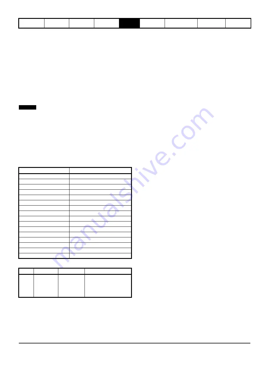
Bit 2 selects either standard or modified register mode. The menu and parameter numbers are derived for each mode as given in the table below.
Standard mode is the default setting and allows up to 99 parameters to be accessed within a menu. Modified mode is provided to allow register
numbers up to 255 to be addressed.
Value
Text
0 (Default)
8 2 NP
1
8 1 NP
2
8 1 EP
3
8 1 OP
4
8 2 NP M
5
8 1 NP M
6
8 1 EP M
7
8 1 OP M
8
7 2 NP
9
7 1 NP
10
7 1 EP
11
7 1 OP
12
7 2 NP M
13
7 1 NP M
14
7 1 EP M
15
7 1 OP M
Bits
3
2
1 and 0
Format
Number of
data bits
0 = 8 bits
1 = 7 bits
Register mode
0 = Standard
1 = Modified
Stop bits and Parity
0 = 2 stop bits, no parity
1 = 1 stop bit, no parity
2 = 1 stop bit, even parity
3 = 1 stop bit, odd parity
NOTE
Summary of Contents for E300 Series
Page 211: ......
Page 212: ...0479 0005 01 ...


